

Aeromotive 18658 User Manual

18657 & 18658 INSTALLATION INSTRUCTIONS
The enclosed Aerom otive fuel tank/pump assembly utilizes an o-ring sealed AN-06 style feed, return and
vent ports. These ports seal with o-rings; these ports are NOT PIPE THREAD and utilize NO THREAD
SEALANT.
The fuel pump used in this tank is the Aeromotive Stealth 340 (part # 11140). To insure proper pump
function and life, we strongly recommend the following
• Utilize AN-06 (EFI) and AN-08 (carb) size high pressure fuel lines, fittings and o-
rings for all connections from the fuel tank to the engine.
• Install a 10 micron post-filter (12301 or 12321).
• Tank must have at least a 3/8” tank vent.
• Fuel pump wiring should be 10 gauge wire and triggered with a relay rated at a
minimum of 20 amps (Aeromotive fuel pump wiring kit 16301).
• A return style regulator must be used (13109-EFI, 13204-carb).
Failure to follow the above recommendations may result in fuel leakage, bursting of the fuel lines, poor
vehicle performance and/or decreased fuel pump life! Improper installation will void all warranties for this
product!
Pump Specifications:
Outlet pressure/flow 40 psi / 340 LPH @ 13.5V
Pump internal By-Pass Pressure 105 psi
Current Draw 13 amps @ 40 psi
Installation of this product requires detailed knowledge of automotive systems and repair
procedures. We recommend that this installation be carried out by a qualified automotive technician.
Installation of this product requires handling of gasoline. Ensure you are working in a well
ventilated area with an approved fire extinguisher nearby. Extinguish all open flames, prohibit
smoking and eliminate all sources of ignition in the area of the vehicle before proceeding with the
installation.
Aeromotive Commonly Used Fittings
15606 AN-06 ORB to AN-06 Flare (Inlet/outlet/vent
fitting)
15649 AN-06 ORB to AN-08 Flare (Inlet/outlet/vent
fitting)
15609 AN-10 ORB to AN-06 Flare (fuel filter fitting)
15610 AN-10 ORB to AN-08 Flare (fuel filter fitting)
Aeromotive AN-10 Fuel Filter P/N’s
12301 Red 10 micron Fuel Filter
12321 Black 10 micron Fuel Filter
12351 Chrome 10 micron Fuel Filter
12335 Red 40 micron Fuel Filter
12305 fuel filter bracket
:
CAUTION:
For AN-06 fuel lines
For AN-08 fuel lines
For AN-06 fuel lines
For AN-08 fuel lines
12304 Red 100 micron Fuel Filter
12324 Black 100 Micron Fuel Filter
12354 Chrome 100 micron Fuel Filter
12331 Black 100 micron Fuel Filter w/ Shutoff Valve
The following steps are typical of most installations:
1. Once the engine has been allowed to cool, disconnect the negative battery cable and relieve
the fuel system pressure.
2. Raise the vehicle and support it with jack stands.
3. Referring to the appropriate vehicle service manual for instructions, drain, disconnect any
electrical and fuel component connections and remove the OEM fuel tank. The removal of the
vehicles exhaust system may be necessary for fuel tank removal.
4. Prep the new Aeromotive Stealth tank by making all the necessary connection (feed, return,
vent and electrical) before placing tank in vehicle. Once the tank is placed in the vehicle
these connection will not be accessible. For electrical wiring refer to Figure 2-1.
NOTE: Tank vent must be at least 6” above the top of the tank. A roll over valve is also
highly recommended.
5. Now route the feed and return line under the vehicle and secure the lines. It’s recommended
to place a post-filter in the feed line (Aeromotive part # 12301/12321). Place the filter in a
location that is easy to get to for servicing.
Note: Be sure to route all fuel lines clear of any moving suspension or drivetrain
components, and any exhaust components! Protect fuel lines from abrasion and road
obstructions or debris.
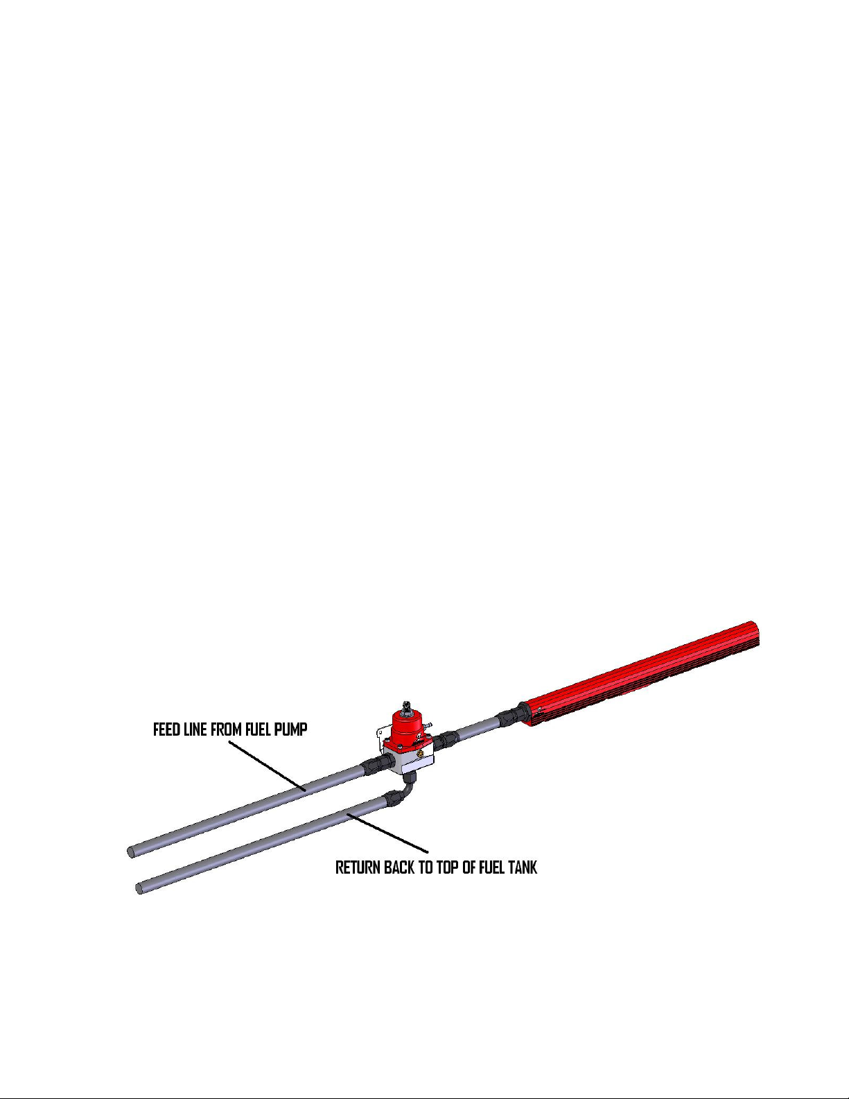
6. The pictures below are typical regulator installations for EFI setups with Aeromotive regulator
part # 13109. Figures 1-1/1-2
Fuel Rail with single inlet (Figure 1-1)
 Loading...