

Aeromotive 17241 User Manual
AEROMOTIVE Part # 17241
BB Chevy Lower Left Mounting
INSTALLATION INSTRUCTIONS
CAUTION:
Installation of this product requires detailed knowledge of automotive systems and repair procedures. We
recommend that a qualified automotive technician carry out this installation.
Installation of this product requires handling of gasoline. Ensure you are working in a well ventilated area
with an approved fire extinguisher nearby. Extinguish all open flames, prohibit smoking and eliminate all sources
of ignition in the area of the vehicle before proceeding with the installation.
When installing this product, wear eye goggles and other safety apparel as needed to protect yourself
from debris and sprayed gasoline.
WARNING!
The fuel system is under pressure. Do not open the fuel system until the pressure has been relieved.
Refer to the appropriate vehicle service manual for the procedure and precautions for relieving the fuel system
pressure.
Aeromotive fuel system components are not legal for sale or use on emission-controlled motor vehicles.
The enclosed Aeromotive fuel pump utilizes an o-ring sealed AN-10 style inlet and outlet ports; these ports are NOT PIPE
THREAD and utilize NO THREAD SEALANT.
A high capacity 100 micron fuel filter must be installed between the fuel tank and pump inlet as well as a high capacity 10
micron fuel filter on the pump outlet. We recommend an Aeromotive P/N 12302 on the inlet side and an Aeromotive P/N
12301 on the outlet side. Call us for info.
To use this pump in your vehicle’s fuel system, we strongly recommend the following
The use of a front mounted fuel cell.
Gravity feed the pump by mounting it lower than the fuel cell.
Utilize AN-10 size high pressure fuel lines, fittings and o-rings for all connections from the
fuel cell to the engine.
Failure to follow the above recommendations may result in fuel leakage, bursting of the fuel lines, poor vehicle
performance and/or decreased fuel pump life! Improper installation will void all warranties for this product!
Performance Specifications: Model 17241
Fuel Compatibility Gasoline & Methyl Alcohol
Port Sizes Inlet & Outlet AN-10
This kit contains the following parts
1 ea p/n 11105 Fuel Pump
1 ea Fuel Pump Bracket
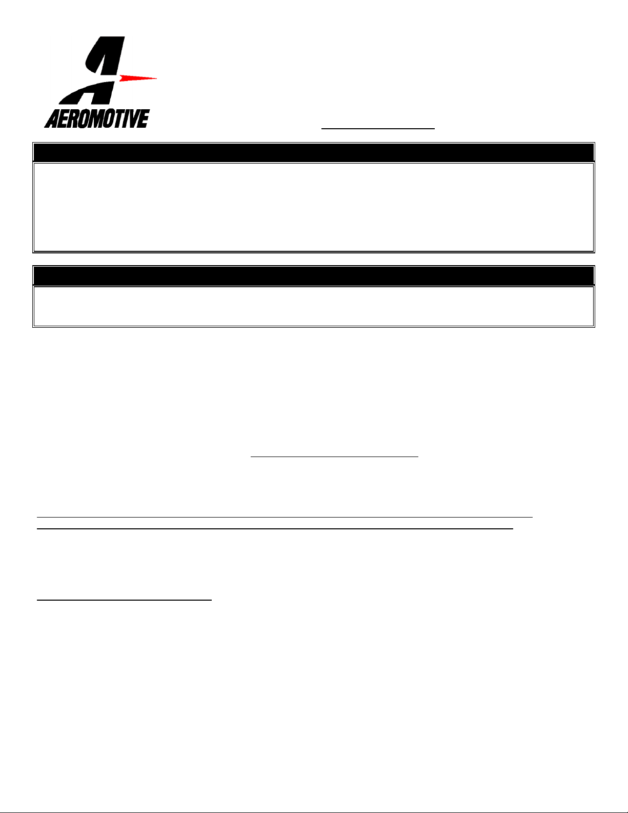
1 ea p/n 21106 BB Chevy Crankshaft Mandrel
1 ea p/n 21108 14-Tooth Crankshaft Pulley
1 ea 28-Tooth Pump Pulley
2 ea Spacers
1 ea Drive Belt
2 ea 1/8” key way
:
Not For Street Use!
:
1 ea 1/4-28 x 1 Socket Head Cap Screw
3 ea 3/8-24 x 1 Socket Head Cap Screws
2 ea 10-32 x 3/16” Setscrew
1 ea 10-32 x ½” Setscrew
2 ea 7/16-14 x 1 ½” Threaded Studs
2 ea 3/8-16 X 1” Bolts
2 ea 3/8” Flat Washers
The following steps are typical of most installations:
1. Once the engine has been allowed to cool, relieve the fuel system pressure and disconnect the negative battery cable.
2. Raise the vehicle and support it with jack stands.
3. Attach the drive mandrel to the front face of the harmonic balancer with 3 of the 3/8-24 x 1 socket head cap screws.
4. Place one of the 1/8” square keys in the keyway on the mandrel.
5. Slide the 14-tooth pulley on to the mandrel
6. Thread the two 10-32 x 3/16” setscrews into the 14-tooth pulley; leave the assembly loose until final alignment can be
determined.
7. Thread each of the 7/16-14 x 1 ½” studs into each of the two spacers
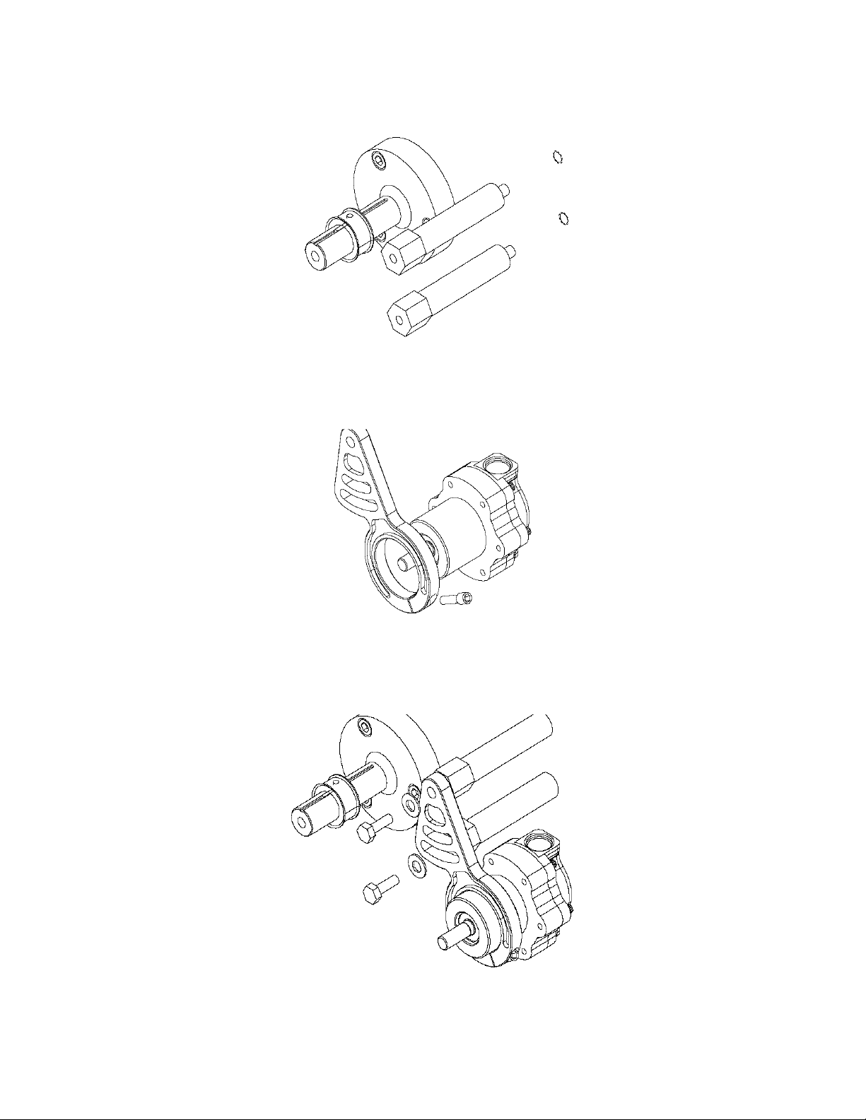
8. Locate the two 7/16” mounting holes on the block, looking at the front of the engine block there will be two 7/16”
threaded holes oriented vertically from each other to the right of the crankshaft. Thread each of the spacer / stud
assemblies into each of the two mounting holes and tighten.
9. Thread the 1/4-28 x 1 socket head cap screw into the bracket but do not tighten.
10. Slide the bracket onto the pump in the orientation shown below;
11. Using the two 3/8-16 X 1” bolts and two 3/8” flat washers attach the fuel pump bracket to the spacers; leave the
assembly loose until final alignment can be determined.
 Loading...