

Aeromotive 17203 User Manual
AEROMOTIVE
Part # 17203
A2000 Fuel Pump / 2 port Regulator System
INSTALLATION INSTRUCTIONS
CAUTION:
Installation of this product requires detailed knowledge of automotive systems and
repair procedures. We recommend that this installation be carried out by a qualified
automotive technician.
Installation of this product requires handling of gasoline. Ensure you are working in a
well ventilated area with an approved fire extinguisher nearby. Extinguish all open flames,
prohibit smoking and eliminate all sources of ignition in the area of the vehicle before
proceeding with the installation.
When installing this product, wear eye goggles and other safety apparel as needed to
protect yourself from debris and sprayed gasoline.
WARNING!
The fuel system is under pressure. Do not open the fuel system until the pressure has
been relieved. Refer to the appropriate vehicle service manual for the procedure and
precautions for relieving the fuel system pressure.
Aeromotive system components are not legal for sale or use on emission controlled motor vehicles.
This kit contains the following parts
1 ea p/n 11202 Pump
1 ea p/n 12304 Filter
1ea p/n 13201 Regulator
2 ea p/n 15201 Dual feed Carburetor Adapter
2 ea p/n 15606 AN-06 cutoff
1 ea p/n 15607 AN-08 cutoff union
3 ea p/n 15608 AN-10 cutoff union
1 ea p/n 15610 AN-10/ AN-08 cutoff union
1 ea p/n 15614 AN-08 / AN-06 union
1 ea p/n 16301 fuel pump wiring kit
4 ea AN-10 O-rings
1 ea AN-08 O-rings
This fuel pump is for race only applications and should not be used for street use!
This fuel pump must be used with a racing style fuel cell.
If you choose not to use a racing style fuel cell, you must install a reservoir style sump in the
bottom-rear of your fuel tank. Exercise extreme caution and follow all manufacturer’s
recommendations when installing a reservoir style sump.
The following steps are typical of most installations:
Section 1 - Fuel pump installation
Section 2 – Fuel Pressure Regulator installation
Section 3 – Fuel line hose end installation
Section 4 – Electrical Installation
Section 5 – Final checks and system start-up
:
3 ea AN-06 O-rings
4 ft AN-10 stainless steel braided line
20 ft AN-08 stainless steel braided line
4 ft AN-06 stainless steel braided line
2 ea AN-06 straight hose end
2 ea AN-06 90-degree hose end
2 ea AN-08 straight hose end
2 ea AN-08 90-degree hose end
2 ea AN-10 straight hose end
2 ea AN-10 90-degree hose end
12 ea tie-wraps
Section 1 - Fuel pump installation:
DO NOT RUN THE PUMP DRY! Excessive wear will result if the pump runs dry.
DO NOT DISASSEMBLE THE PUMP! Disassembly will throw the pump out of calibration and void all warranties on this
product.
1-1. Once the engine has been allowed to cool, disconnect the negative battery cable and relieve the fuel system
pressure.
1-2. Raise the vehicle and support it with jack stands.
1-3. Referring to the appropriate vehicle service manual for instructions, drain, disconnect any electrical and fuel
component connections, plug the open fuel line ends and remove the existing pump.
1-4. Find a suitable place on the vehicle chassis to mount the Aeromotive fuel pump. Make sure the location will
accommodate the pump mounting bolts, will position the pump lower than the fuel tank, is clear of the exhaust, is
clear of any moving suspension or drivetrain components and will keep the pump clear of road obstructions or debris.
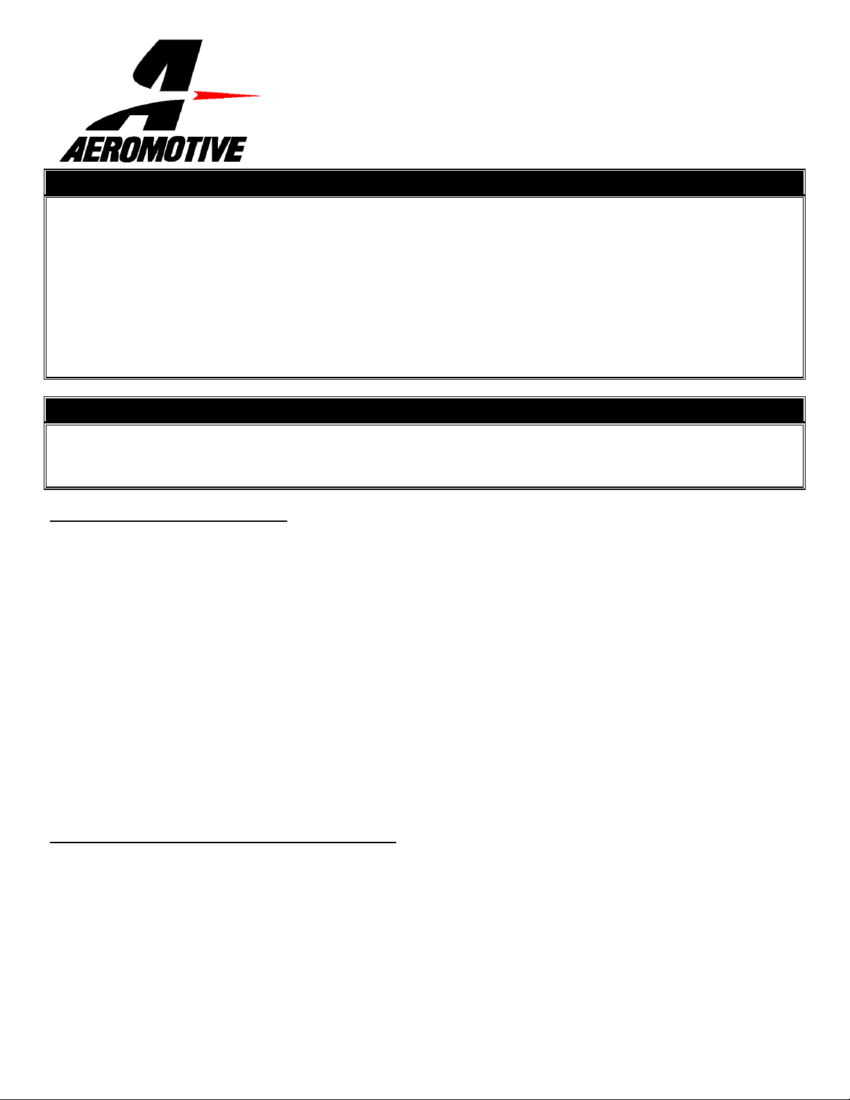
1-5. Place one of the supplied AN-10 o-rings on the cutoff side of each of the three AN-10 cutoff unions and the AN-10 /
AN-08 cutoff union.
1-6. Thread one of the above AN-10 fittings into the fuel pump inlet and thread the AN-10 / AN-08 cutoff union from above
into the fuel pump outlet and tighten.
1-7. Thread an AN-10 fitting with o-ring into each side of the fuel filter and tighten.
1-8. Making sure to mount the pump in the upright position and using the pump mounting bracket as a template, mark and
drill two mounting holes to accept ¼” bolts (not provided). Mount the pump bracket using two ¼” bolts, nuts and lock
washers (Not provided).
Note: Be sure to route all fuel lines clear of any moving suspension or drivetrain components, and any exhaust
components! Protect fuel lines from abrasion and road obstructions or debris.
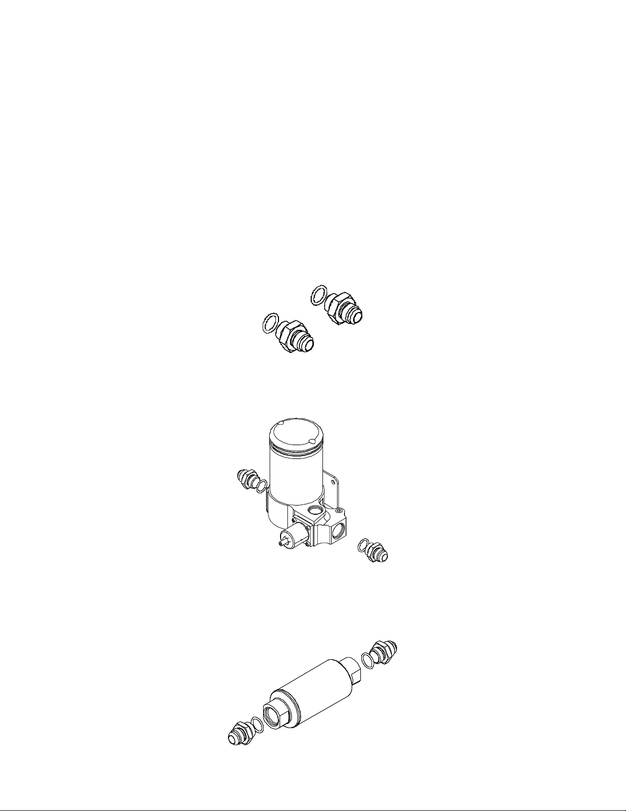
1-9. Using the system diagram below, determine the approximate location of the fuel filter in the system.
1-10. Using one of the supplied 90-degree AN-10 hose ends and one of the supplied AN-10 straight hose ends as a
guide, measure the length of AN-10 steel braided line needed to connect the fuel tank or fuel cell outlet to the fuel
filter inlet. This section of fuel line should be as short as possible to reduce the tendencies for vapor lock, cavitation,
and premature wear of your Aeromotive fuel pump.
1-11. Cut and assemble the steel braided hose and hose ends as shown in Section 3.
1-12. Using the above steel braided line assembly, connect the hose ends to their appropriate locations and tighten.
1-13. Repeat steps 1-10 thru 1-12 for the AN-10 steel braided line between the fuel filter outlet and fuel pump inlet.
1-14. In the vehicles engine compartment determine where the fuel pressure regulator will be mounted.
Note: Be sure to route all fuel lines clear of any moving suspension or drivetrain components, and any exhaust
components! Protect fuel lines from abrasion and road obstructions or debris.
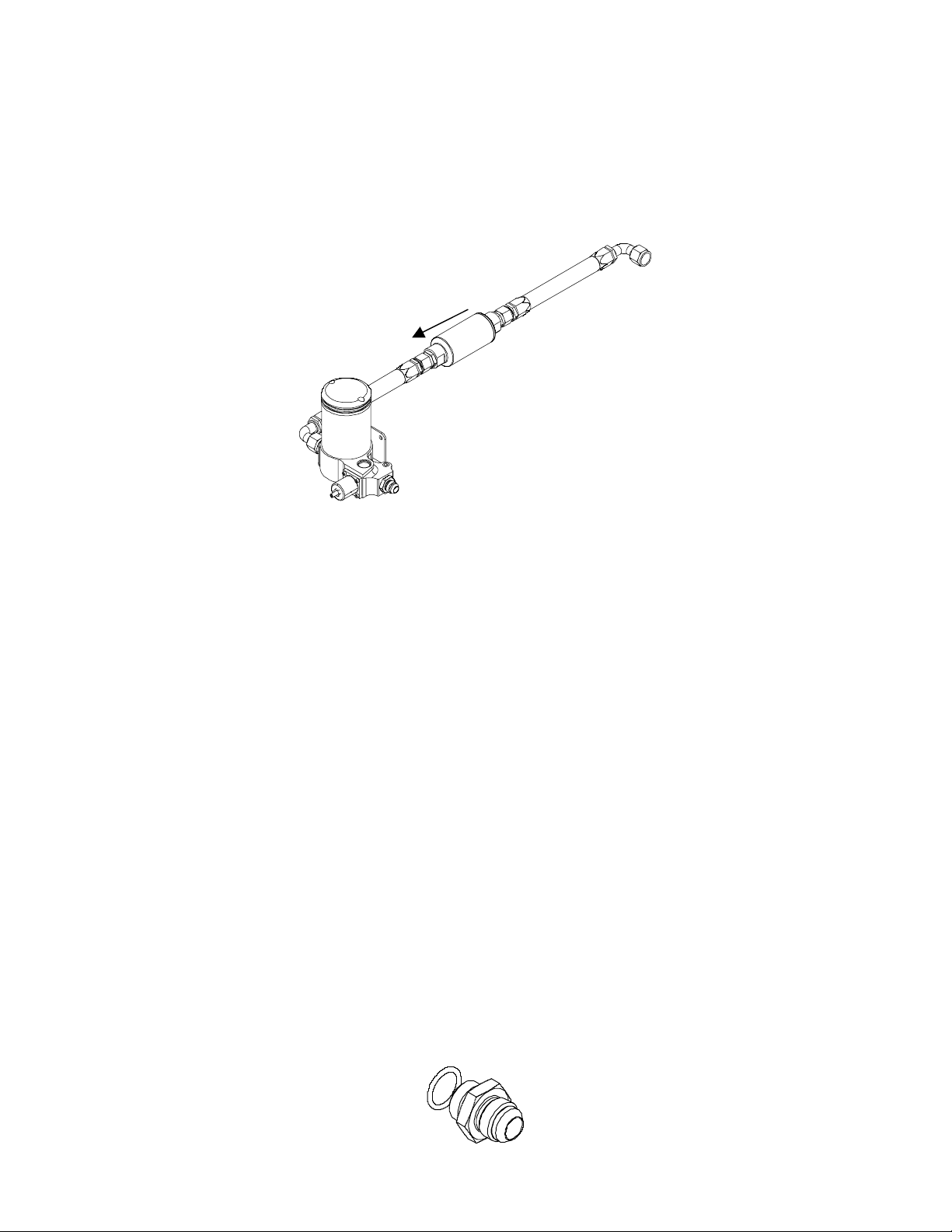
1-15. Using one of the supplied AN-08 90-degree hose ends and one of the supplied AN-08 straight hose ends as a
guide, measure the length of AN-08 steel braided line needed to connect the fuel pump outlet to your fuel pressure
regulator.
1-16. Cut and assemble the steel braided hose and hose ends as shown in Section 3.
1-17. Using the above steel braided hose assembly, connect the hose ends to their appropriate locations and tighten.
Note: Be sure to route all fuel lines clear of any moving suspension or drivetrain components, and any exhaust
components! Protect fuel lines from abrasion and road obstructions or debris.
1-18. Place the supplied AN-08 o-ring on the cutoff side of the AN-08 cutoff union.
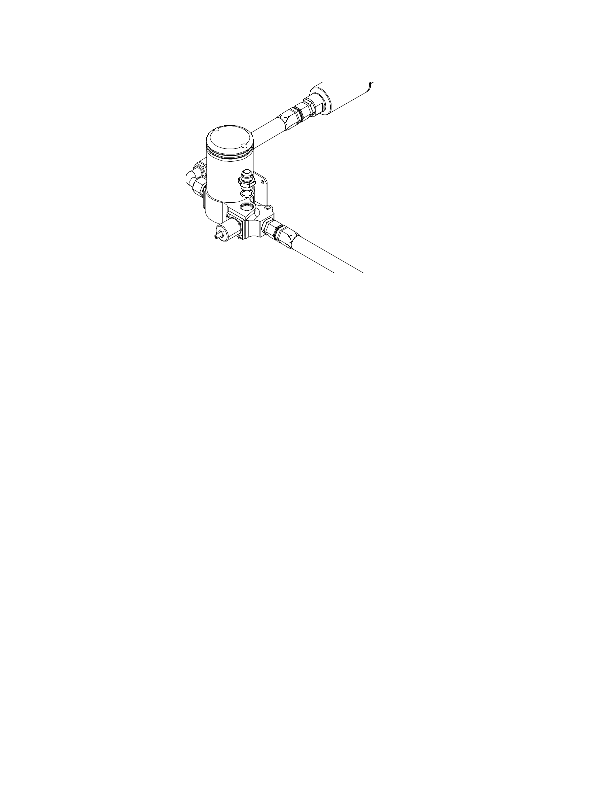
1-19. Thread the AN-08 fitting with o-ring into the by-pass port located on top of the fuel pump.
1-20. Using the supplied 90-degree AN-08 hose end and the supplied AN-08 straight hose end as a guide, measure the
length of AN-08 steel braided line needed to connect the fuel pump by-pass port to the top of the fuel cell.
Note: Be sure to route all fuel lines clear of any moving suspension or drivetrain components, and any exhaust
components! Protect fuel lines from abrasion and road obstructions or debris.
1-21. Cut and assemble the steel braided hose and hose ends as shown in Section 3.
1-22. Using the above steel braided hose assembly, connect the hose ends to their appropriate locations and tighten.
 Loading...