

Aeromotive 17158 User Manual
AEROMOTIVE
Part # 17158
05’- Present Mustang Race Fuel System Kit
INSTALLATION INSTRUCTIONS
CAUTION:
Installation of this product requires detailed knowledge of automotive systems and
repair procedures. We recommend that this installation be carried out by a qualified
automotive technician.
Installation of this product requires handling of gasoline. Ensure you are working in a
well ventilated area with an approved fire extinguisher nearby. Extinguish all open flames,
prohibit smoking and eliminate all sources of ignition in the area of the vehicle before
proceeding with the installation.
When installing this product, wear eye goggles and other safety apparel as needed to
protect yourself from debris and sprayed gasoline.
WARNING!
The fuel system is under pressure. Do not open the fuel system until the pressure has
been relieved. Refer to the appropriate vehicle service manual for the procedure and
precautions for relieving the fuel system pressure.
Aeromotive system components are not legal for sale or use on emission controlled motor vehicles.
This kit contains the following parts
1 ea fuel filter bracket (12305)
1 ea fuel filter (12321)
1ea p/n 14141 Ford 5.4L DOHC Fuel Rails
1ea p/n 13128 EFI Regulator
1ea p/n 15115 Ford Adapter Fuel Pressure Senor
1ea p/n 15102 Supply Adapter Tee Fitting
6ea p/n 15607 AN-08 To Cutoff AN-08 Union
5 ea p/n 15610 AN-08 to cutoff AN-10 union
1ea p/n 15631 Fuel Sample Valve
2 ea p/n 15645 AN-08 tank fitting
9ea p/n 15653 –8 Straight Hose End
3ea p/n 15654 -8 45-degree Hose End
Section 1 - Fuel system installation, Chassis:
1-1. Once the engine has been allowed to cool, disconnect the negative battery cable and relieve the fuel system pressure.
1-2. Raise the vehicle and support it with jack stands.
1-3. Referring to the appropriate vehicle service manual for instructions, drain, disconnect any electrical and fuel
component connections and remove the OEM fuel tank. The removal of the vehicles drive shaft and exhaust system
may be necessary for fuel tank removal.
1-4. Once the OEM fuel tank has been removed, tie up all electrical connections and hoses that were disconnected.
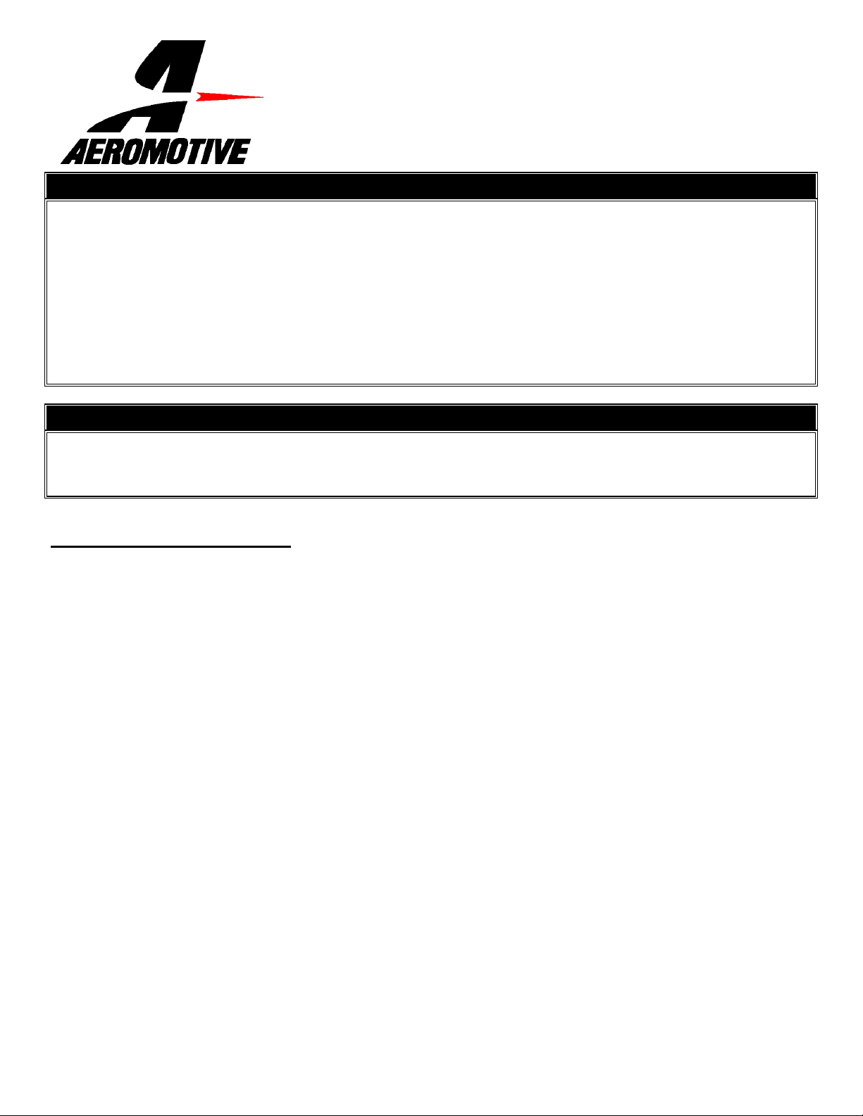
1-5. Find a suitable place in the trunk to mount the fuel cell. For mounting use Aeromotive bracket P/N 18701, or call
Aeromotive. Pictured is a typical install of a fuel cell in a SN197, Figure 1-1.
:
13ea p/n 15655 –8 90-Degree Hose End
3ea p/n 15663 -8 180-Degree Hose End
1ea p/n 15649 AN-06 Cutoff To AN-08 Union
1ea p/n 15674 Y-Block 8-2x8
4 ea p/n 15685 AN-08 bulkhead fitting
12 ea cushioned hose clamps
12 ea self-drilling screw
3ea p/n 17704 Triple AN-08 Hose Separator
1 ea fuel cell (18667)
1ea Vacuum Tee
50ft –8 Black Nylon Braided Fuel Line
3ft 5/32” Vacuum Line
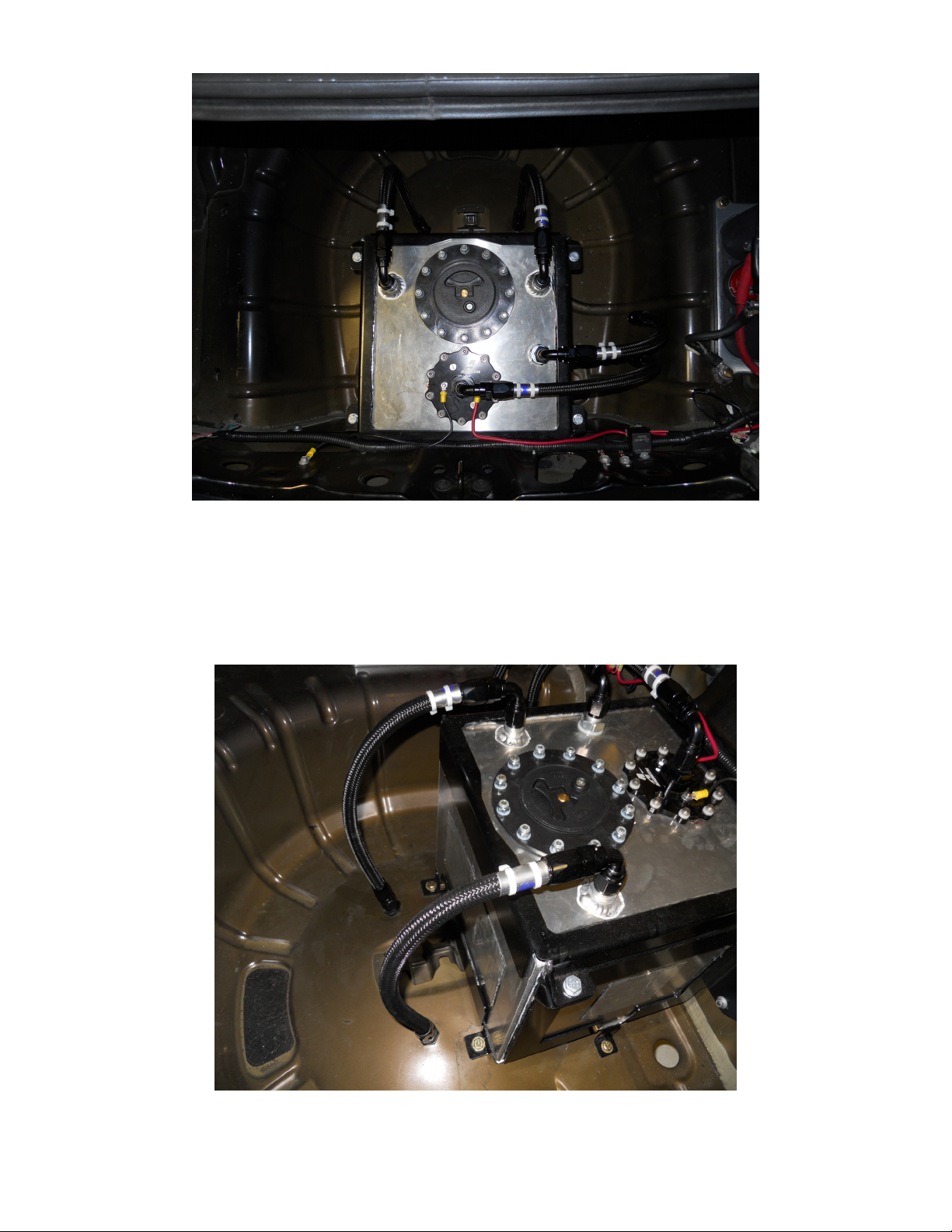
Figure 1-1
1-6. Find a suitable place for the two tank vent pass through fittings (15645), typical locations is trunk floor. Drill two holes
making sure you place them in a location where you can get access to the back side for the lock nuts. The system
comes with two tanks vents and both must be used for the system to function properly.
1-7. Assembly two identical hoses, 90 degree hose end on one side and a straight on the other. These will be used for the
tank vent hoses, Figure 1-2.
Figure 1-2
1-8. Next find a place for the two AN-08 fuel bulk heads, p/n 15685. The most common place for the two bulk heads are
on the driver’s side in the spare tire well. Drill the two holes two inches apart, Figure 1-3.
Figure 1-3
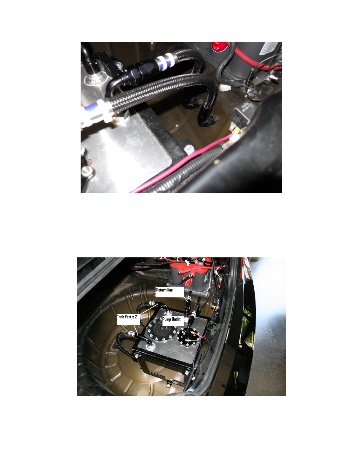
1-9. Install one of the supplied 15610 fittings into the outlet of fuel pump (Make sure the fitting has the AN-10 o-ring
installed on it).
1-10. Assembly two hoses, both with 90-degree hose end on all ends. One will be used for the pump outlet and the other
will be used for the return, Figure 1-4.
Figure 1-4
1-11. After connecting the return and pump outlet lines to the bulk heads, move to the under side of the vehicle.
1-12. Find a location for the fuel filter (12321) and mounting bracket (12305). Typical mounting location on the passenger
side frame rail, Figure 1-5.
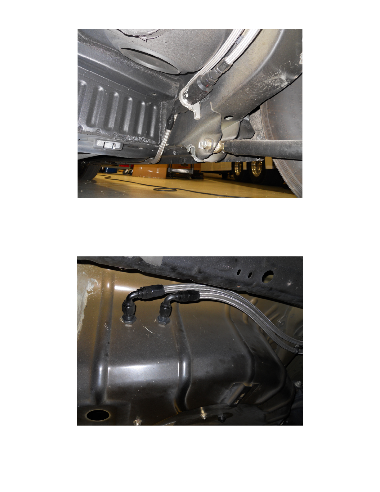
Figure 1-5
1-13. Once the filter has been mounted, assemble a hose with a 90-degree fitting on one end and a straight on the other.
This line will finish the connection from the feed bulk head to the filter, Figure 1-6. NOTE: Make sure you connect to
the pump outlet and not the return.
Figure 1-6
1-14. In the engine bay find a suitable place for the two AN-08 bulk heads. Typical place for these are behind the
passenger side strut tower, Figure 1-7.
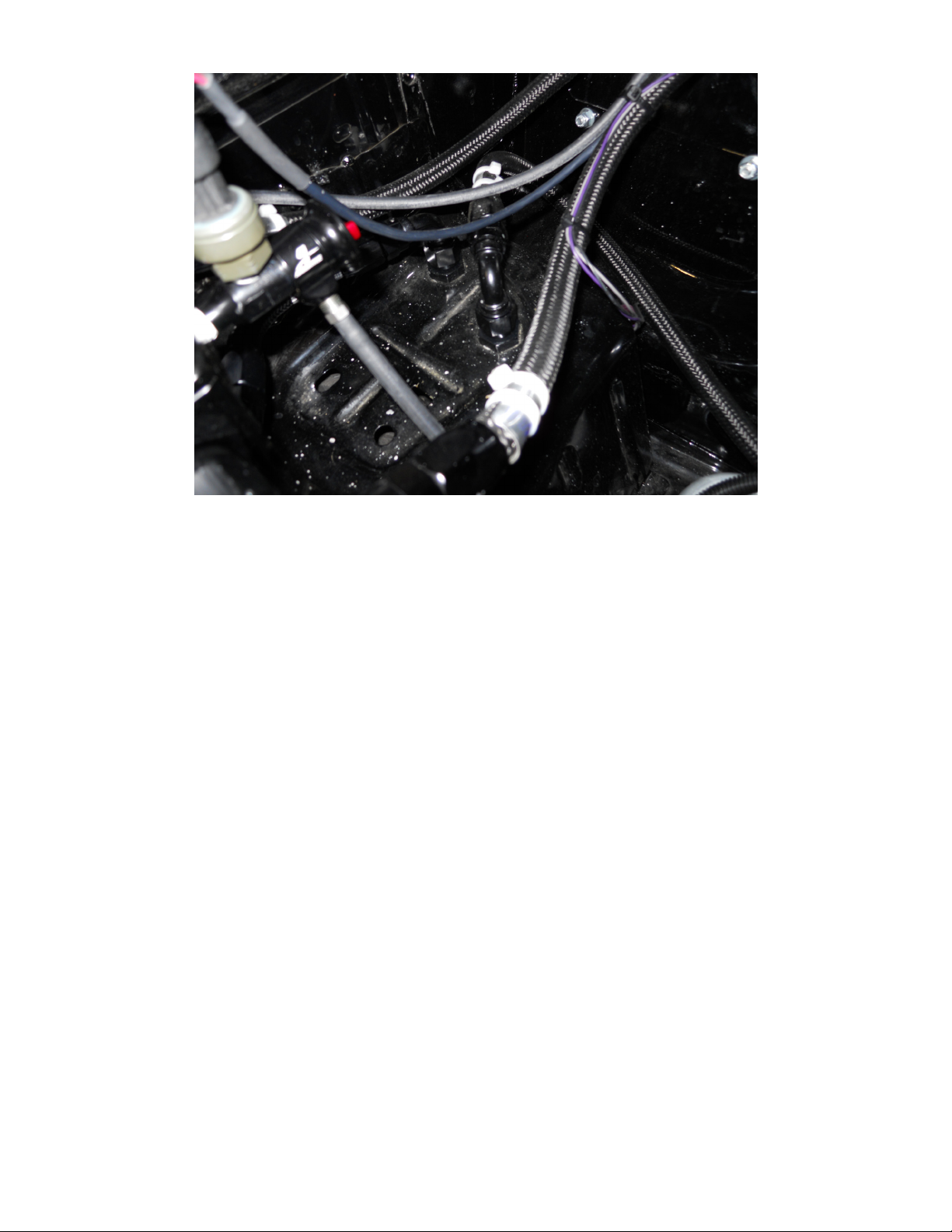
Figure 1-7
1-15. Once you have both bulk heads installed, assemble a hose with a 45-degree fitting on one end and a straight on the
other. This line will connect to the outlet of the fuel filter (45-degree hose end) and one of the bulk heads you just
installed.
1-16. Finish up the last line by assembling a hose with a straight hose end on one side and a 90-degree on the other.
This hose will make the connection from the return bulk head in the engine bay to the return bulk head in the trunk.
1-17. Now use the cushioned hose clamps to attach the lines to the body of the vehicle. Note: Be sure to route all fuel
lines clear of any moving suspension or drivetrain components and any exhaust components! Protect fuel
lines from abrasion and road obstructions or debris.
1-18. For pump wiring, use Aeromotive part # 16301.
Section 2 – Engine Fuel Install:
The following steps are typical of most installations:
2-1. Remove the air intake ducting from the throttle body.
2-2. Note the location of and remove any vacuum lines connected to the air intake and position them out of the way.
2-3. Unplug the TPS sensor and drive-by wire connector, which is typically located on top of the throttle body.
2-4. Remove the throttle body by removing 4 screws.
2-5. Now remove the blower inlet tube by removing the 4 bolts.
2-6. Check for any dirt or debris around the fuel injectors. If any is evident, wash it off with some solvent parts cleaner or
wipe it off with a clean shop towel.
 Loading...