

Aeromotive 17145 User Manual
AEROMOTIVE
Part # 17145 & 17146
98 ½-04 4.6L DOHC Return Style Fuel System Kit
INSTALLATION INSTRUCTIONS
CAUTION:
Installation of this product requires detailed knowledge of automotive systems and
repair procedures. We recommend that this installation be carried out by a qualified
automotive technician.
Installation of this product requires handling of gasoline. Ensure you are working in a
well ventilated area with an approved fire extinguisher nearby. Extinguish all open flames,
prohibit smoking and eliminate all sources of ignition in the area of the vehicle before
proceeding with the installation.
When installing this product, wear eye goggles and other safety apparel as needed to
protect yourself from debris and sprayed gasoline.
WARNING!
The fuel system is under pressure. Do not open the fuel system until the pressure has
been relieved. Refer to the appropriate vehicle service manual for the procedure and
precautions for relieving the fuel system pressure.
Aeromotive system components are not legal for sale or use on emission controlled motor vehicles.
This kit assumes you have a sumped fuel tank or fuel cell with provisions for a gravity feed AN-10 supply line and
AN-06 return line.
This kit contains the following parts
1 ea fuel pump wiring kit
1 ea 3ft length of 10 ga. Black wire
1 ea 25ft length of 10 ga. Red wire
1 ea 30 amp circuit breaker
1 ea 30 amp automotive relay
2 ea blue female blade connector
2 ea yellow female blade connector
5 ea yellow #10 stud ring connector
1 ea yellow 3/8” stud ring connector
6 ea tie-wraps
4 ft AN-10 stainless steel braided line
16 ft AN-06 stainless steel braided line
26 ft AN-08 stainless steel braided line
2 ea AN-10 90-degree hose end
2 ea AN-08 straight hose end
6 ea AN-08 90-degree hose end
2 ea AN-08 Male 90-degree hose end
1 ea AN-06 straight hose end
1 ea AN-06 90-degree hose end
1 ea p/n 11101 Pump (17145 Kit only)
1 ea p/n 11104 Pump (17146 Kit only)
1 ea p/n 12304 Filter 100 Micron SS
1 ea p/n 12301 Filter 10 Micron Paper
:
1 ea p/n 13101 Fuel Pressure Regulator
1 ea p/n 14111 Ford 4.6L DOHC Fuel Rails
1 ea Y-block Assembly
2 ea p/n 15607 AN-08 cutoff union
2 ea AN-08 o-ring
1 ea p/n 15610 AN-10 cutoff to AN-08 union
1 ea AN-10 o-ring
4 ea ¼” flat washers
4 ea ¼-20 nyloc nuts
4 ea ¼-20 x 1” carriage bolts
12 ea tie-wraps
1 ea AN-06 o-ring
4 ea AN-08 o-ring
8 ea AN-10 o-ring (17145 kit only)
7 ea AN-10 o-ring (17146 kit only)
1 ea AN-12 o-ring (17146 kit only)
1 ea p/n 15606 AN-06 cutoff union
2 ea p/n 15607 AN-08 cutoff union
3 ea p/n 15608 AN-10 cutoff union (17145 kit only)
2 ea p/n 15608 AN-10 cutoff union (17146 kit only)
3 ea p/n 15610 AN-10 cutoff to AN-08 union
1 ea p/n 15613
AN-12 cutoff to AN-10 union (17146 kit only)
f
p
Warning – The included Aeromotive fuel pump is not compatible with alcohol based fuels or
fuel additives!
The following steps are typical of most installations:
Section 1 - Fuel Pump Installation
Section 2 – Fuel Rail Installation
Section 3 – Fuel Regulator Installation and Fuel Line Plumbing
Section 4 – Fuel Line Hose End Installation
Section 5 – Electrical Installation
Section 6 – Final Checks and System Start-up
Fuel Pump Template
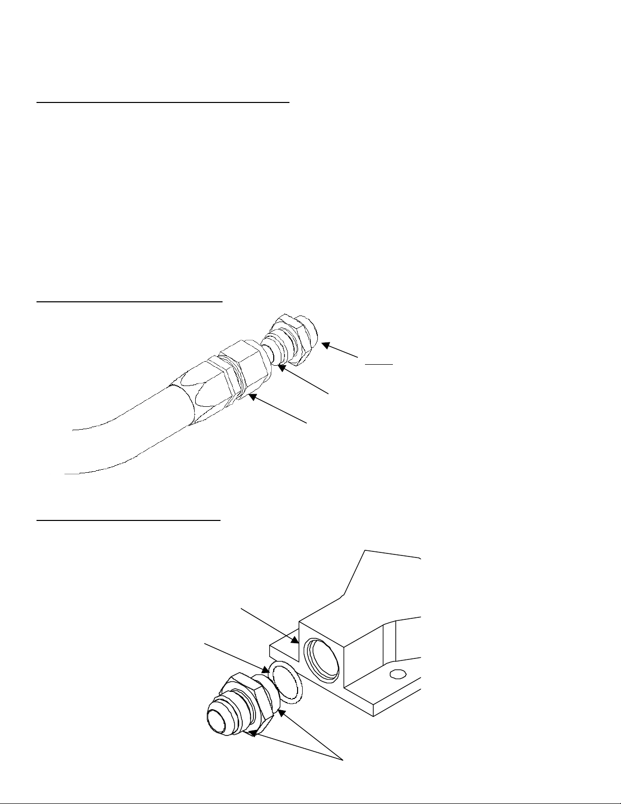
Typical hose end to fitting connection:
Typical o-ring sealed port connection:
O-ring sealed AN style port
O-ring
(Install on union fitting between back o
threads and face of hex nut.)
Do not connect hose end to cutoff side of union!
Connect hose end to 37-degree flare side of union.
Hose End
Typically the cutoff side of the union is used as
the o-ring sealed side, leaving the 37-degree
flare side for your hose end connection. In some
cases both sides of the union utilize an o-ring
seal. For example, in this kit a union connects
the both
orts of the fuel pump and filter.
Section 1 - Fuel Pump Installation:
1-1. Once the engine has been allowed to cool, disconnect the negative battery cable and relieve the fuel system
pressure.
1-2. Raise the vehicle and support it with jack stands.
1-3. Find a suitable mounting location for your Aeromotive fuel pump / filter assembly, the following steps outline mounting
the assembly on the OE plastic fuel tank shield. If you choose not to mount the pump / filter assembly to this shield
adjust the installation procedure as necessary.
1-4. Referring to the appropriate vehicle service manual for instructions, drain, disconnect any electrical and fuel
component connections and remove the OEM fuel tank. The removal of the vehicles exhaust system may be
necessary for fuel tank removal.
1-5. Once the OEM fuel tank has been removed, remove the plastic fuel tank shield from the bottom of the tank.
1-6. If you have kit 17143:
In the kit find two AN-10 cutoff union fittings and four of the AN-10 o-rings. Install each of the
four o-rings on each end of the two AN-10 cutoff union fittings.
If you have kit 17144:
In the kit find one AN-10 cutoff union fitting, one AN-12 cutoff to AN-10 union fitting, the AN-12
o-ring and three of the AN-10 o-rings. Install each of the four o-rings on the appropriate ends of
the two fittings.
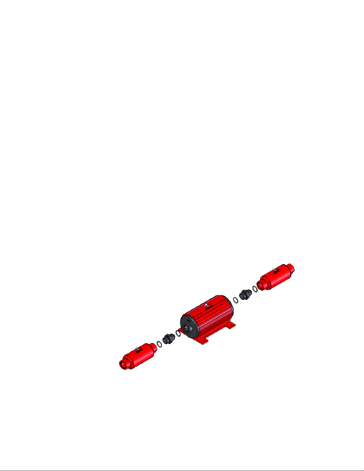
1-7. Install each of the two AN-10 cutoff fittings into each end of the provided Aeromotive fuel pump.
1-8. Noting the appropriate flow directions, install the provided fuel filter, Aeromotive p/n 12301, on the fuel pump outlet
and the other fuel filter, Aeromotive p/n 12304, on the fuel pump inlet.
1-9. Install one of the supplied AN-10 o-rings on the cutoff side of the AN-10 cutoff union fitting, if not already installed,
and install on the inlet side of the pump / filter assembly.
1-10. Install one of the supplied AN-10 o-rings on the AN-10 cutoff side of the AN-10 cutoff to AN-08 reducer union fitting,
if not already installed, and install on the outlet side of the pump / filter assembly.
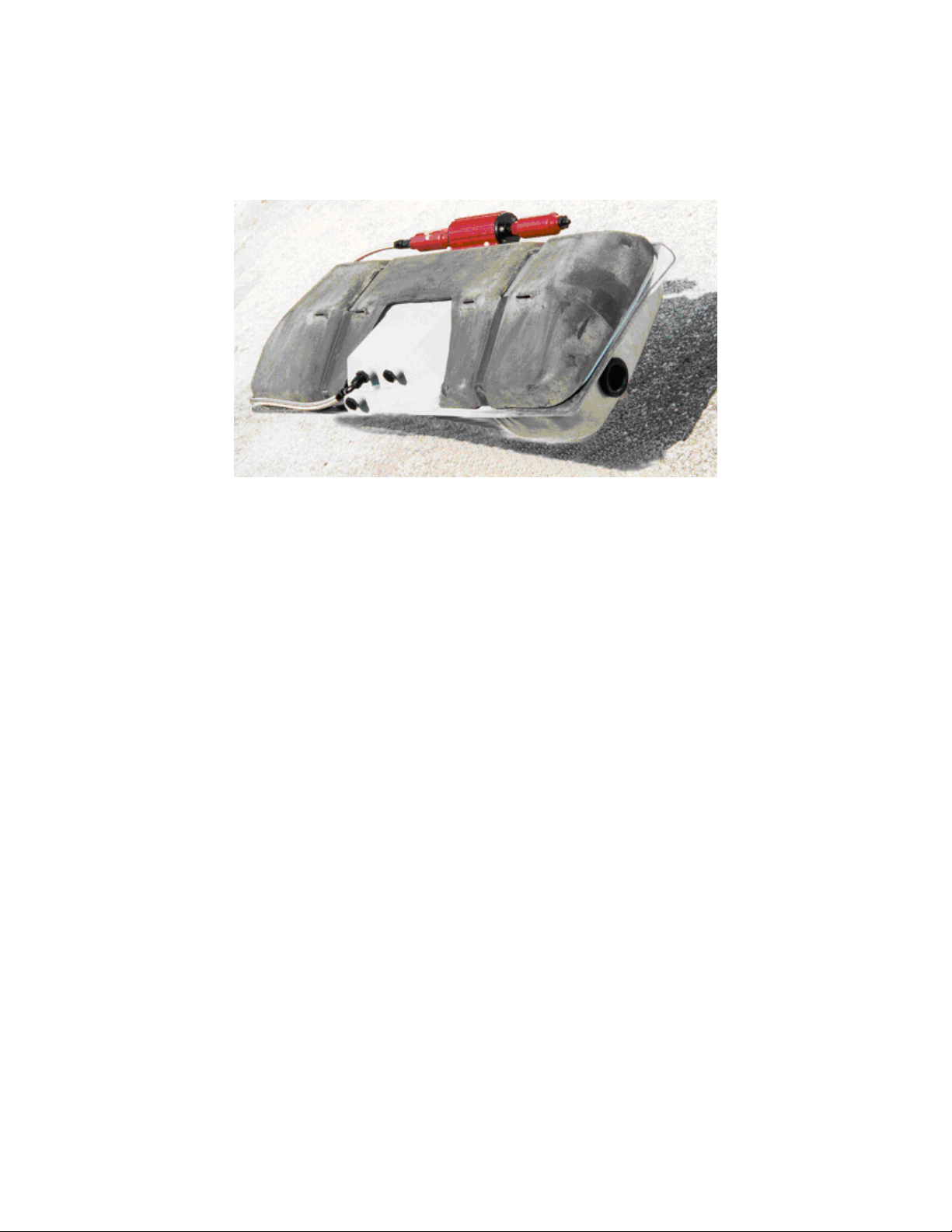
Figure 1-2
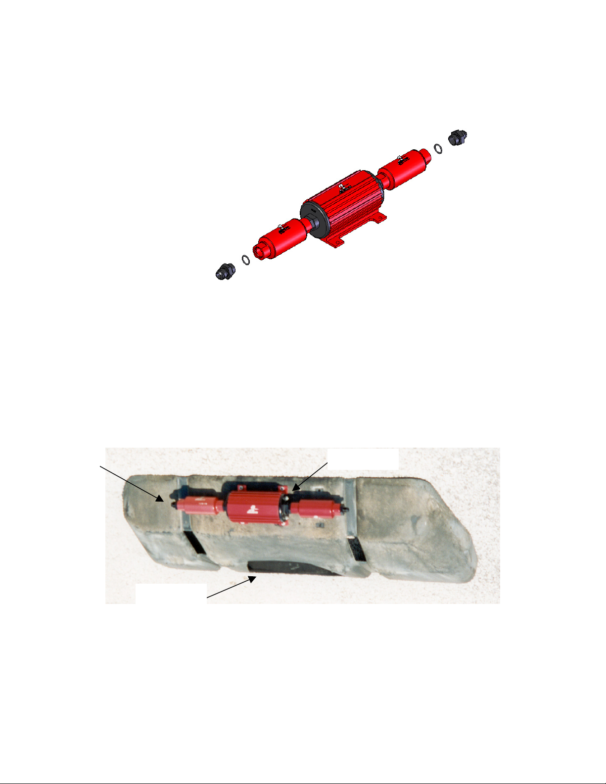
1-11. Position the fuel pump / filter assembly from above on the opposite end of the plastic fuel tank shield as the sump
cutout. Center the pump / filter assembly in all directions on the flat. Using the fuel pump as a guide, mark the four
pump mounting holes. Insure there are no obstructions behind the plastic fuel tank shield and drill four ¼” mounting
holes.
1-12. The fuel pump should be installed such that when the plastic fuel tank shield is installed the fuel pump outlet is on
the driver side of the vehicle. Secure the fuel pump to the plastic fuel tank shield by installing each of the four ¼”
carriage bolts from the inside of the fuel tank shield, through the fuel tank shield and through the fuel pump mounting
holes. Install each of the four provided flat washers and nuts on the bolts and tighten. The plastic fuel tank shield now
should look similar to the one shown below.
Inlet
Pump outlet
Sump Cutout
1-13. Inspect the inside of the plastic fuel tank shield for any sharp edges that could puncture the fuel tank. If any sharp
edges are found, correct before proceeding.
1-14. Position the plastic fuel tank shield on the Aeromotive fuel tank.
1-15. Using the two supplied 90-degree AN-10 hose ends as a guide, measure the length of AN-10 steel braided line
needed to connect the fuel tank sump outlet to the fuel pump / filter assembly inlet.
1-16. Cut and assemble the steel braided hose and hose ends as shown in Section 4.
1-17. Using the above steel braided hose assembly, connect one end to the outlet of the fuel tank sump and the other
end to the fuel pump / filter assembly inlet and tighten.
Note: It is recommended that a fuel shut off valve be installed between the fuel tank outlet and the fuel pump /
filter assembly inlet, these valves are available from most popular racing fitting manufactures; Aeroquip,
Earl’s, Goodridge, Russell, etc.
1-18. Using any type of household tape, secure the plastic fuel tank shield to the Aeromotive fuel tank along each of the
fuel tank strap indentations.
1-19. Carefully flip the fuel tank / plastic fuel tank shield assembly over.
1-20. Position the fuel tank under the vehicle. Apply a light weight oil to the filler neck grommet to ease installation.
1-21. In vehicles engine compartment, locate a suitable mounting location for the supplied fuel pressure regulator
1-22. Starting from the decided regulator mounting location in the engine compartment, plan a route to run an AN-06
return line back to your fuel tank / fuel cell AN-06 return port and measure the required length. Cut the return line to
the determined length and install one AN-06 90-degree hose end and one AN-06 straight hose end, as detailed in
Section 4.
Note: Be sure to route all fuel lines clear of any moving suspension or drivetrain components and any exhaust
components! Protect fuel lines from abrasion and road obstructions or debris.
1-23. Thread the 90-degree hose end side of the AN-06 return line onto the AN-06 return port fitting located on your
sumped fuel tank / fuel cell, and tighten.
1-24. As your fuel tank is lifted into position reattach the vent line to the top of the fuel tank and work the filler neck in to
the grommet on the side of the fuel tank. Once your fuel tank is in position, align tank straps, ensure that there are not
any hoses or wiring pinched and tighten the strap bolts.
1-25. Make any line or electrical adjustments necessary to clear the vehicles exhaust, suspension, and drivetrain
components.
 Loading...