

Aeromotive 17135 User Manual
AEROMOTIVE
Part # 17135 & 17136
Generic Fuel System Kit
INSTALLATION INSTRUCTIONS
CAUTION:
Installation of this product requires detailed knowledge of automotive systems and
repair procedures. We recommend that this installation be carried out by a qualified
automotive technician.
Installation of this product requires handling of gasoline. Ensure you are working in a
well ventilated area with an approved fire extinguisher nearby. Extinguish all open flames,
prohibit smoking and eliminate all sources of ignition in the area of the vehicle before
proceeding with the installation.
When installing this product, wear eye goggles and other safety apparel as needed to
protect yourself from debris and sprayed gasoline.
WARNING!
The fuel system is under pressure. Do not open the fuel system until the pressure has
been relieved. Refer to the appropriate vehicle service manual for the procedure and
precautions for relieving the fuel system pressure.
Aeromotive system components are not legal for sale or use on emission controlled motor vehicles.
This kit contains the following parts
1 ea fuel pump wiring kit
1 ea 3ft length of 10 ga. Black wire
1 ea 25ft length of 10 ga. Red wire
1 ea 30 amp circuit breaker
1 ea 30 amp automotive relay
2 ea blue female blade connector
2 ea yellow female blade connector
5 ea yellow #10 stud ring connector
1 ea yellow 3/8” stud ring connector
6 ea tie-wraps
4 ft AN-08 stainless steel braided line
40 ft AN-06 stainless steel braided line
1 ea AN-08 90-degree hose end
1 ea AN-08 straight hose end
6 ea AN-06 straight hose end
2 ea AN-06 90-degree hose end
Warning – The included Aeromotive fuel pump is not compatible with alcohol based fuels or
fuel additives!
This kit assumes you have a sumped fuel tank or fuel cell with accommodations for an AN-08
Supply line and an AN-06 return line. Fuel tank pickups will not work properly with
Aeromotive fuel systems and will be detrimental to your fuel systems life. If your fuel tank is
not sumped, we recommend having your fuel tank sumped by a qualified professional.
No fuel rails are provided with this kit, your fuel rails must have accommodations to accept
AN-06 hose ends in order to install this kit properly. This kit only provides provisions for one
AN-06 supply line to the fuel rail(s), for vehicles with more then one fuel rail, Aeromotive
recommends using a Y-block and feeding each fuel rail separately, call Aeromotive for details.
:
1 ea p/n 11103 or 11106 Pump
1 ea p/n 12304 Filter 100 Micron SS
1 ea p/n 12301 Filter 10 Micron Paper
1 ea p/n 13109 Fuel Pressure Regulator
12 ea tie-wraps
4 ea AN-06 o-ring
1 ea AN-08 o-ring
4 ea AN-10 o-ring
3 ea p/n 15606 AN-06 cutoff union
2 ea p/n 15609 AN-10 cutoff to AN-06 union
2 ea p/n 15610 AN-10 cutoff to AN-08 union
f
The following steps are typical of most installations:
Section 1 - Fuel Pump Installation
Section 2 – Fuel Regulator Installation and Fuel Line Plumbing
Section 3 – Fuel Line Hose End Installation
Section 4 – Electrical Installation
Section 5 – Final Checks and System Start-up
Fuel Pump Template
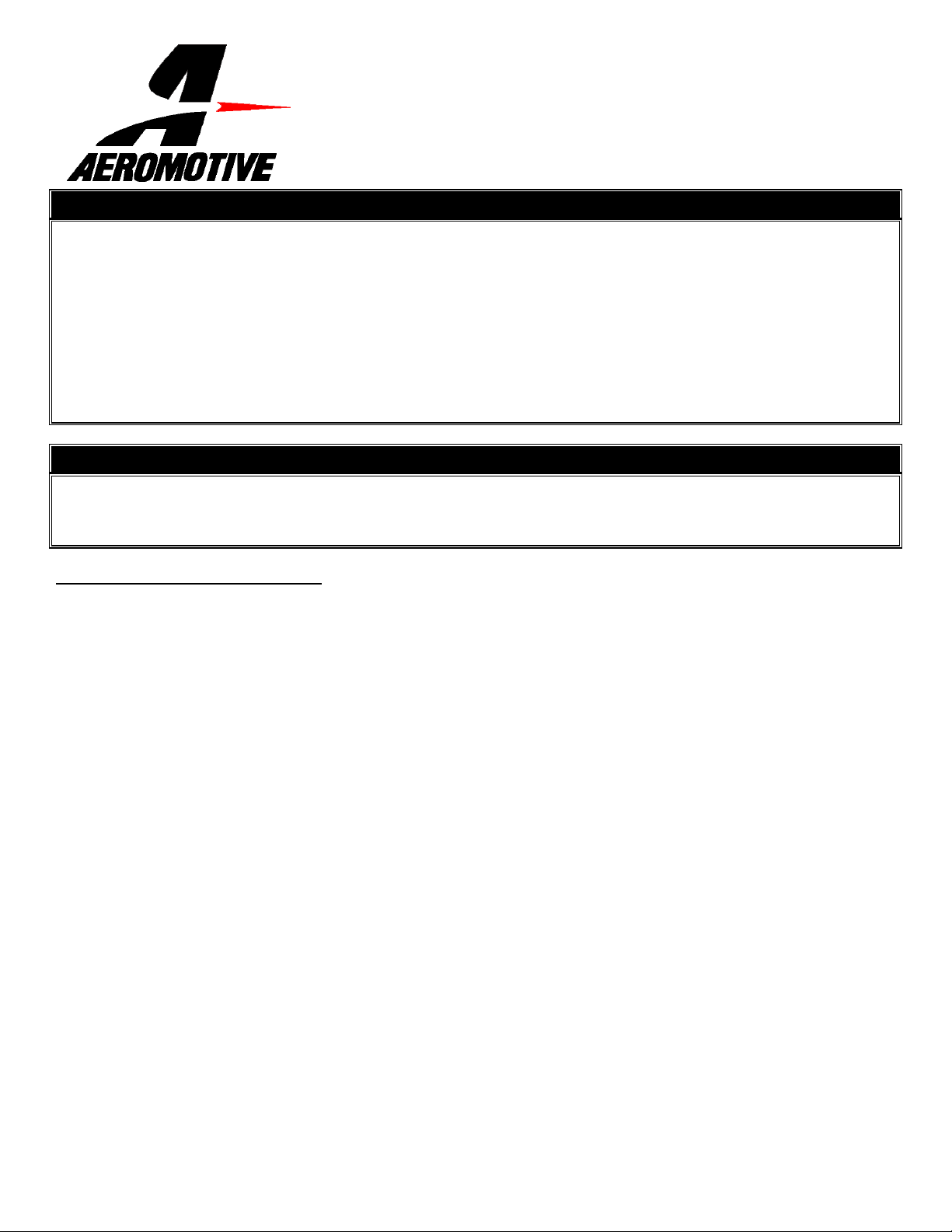
Typical hose end to fitting connection:
Do not connect hose end to cutoff side of union!
Connect hose end to 37-degree flare side of union.
Typical o-ring sealed port connection:
O-ring sealed AN style port
O-ring
(Install on union fitting between back o
threads and face of hex nut.)
Hose End
Typically the cutoff side of the union is used as
the o-ring sealed side, leaving the 37-degree
flare side for your hose end connection. In some
cases both sides of the union utilize an o-ring
seal. For example, in this kit a union connects
the port of the fuel pump and filter.
Section 1 - Fuel Pump Installation:
1-1. Once the engine has been allowed to cool, disconnect the negative battery cable and relieve the fuel system
pressure.
1-2. Raise the vehicle and support it with jack stands.
1-3. Referring to the appropriate vehicle service manual for instructions, drain, disconnect any electrical and fuel
component connections.
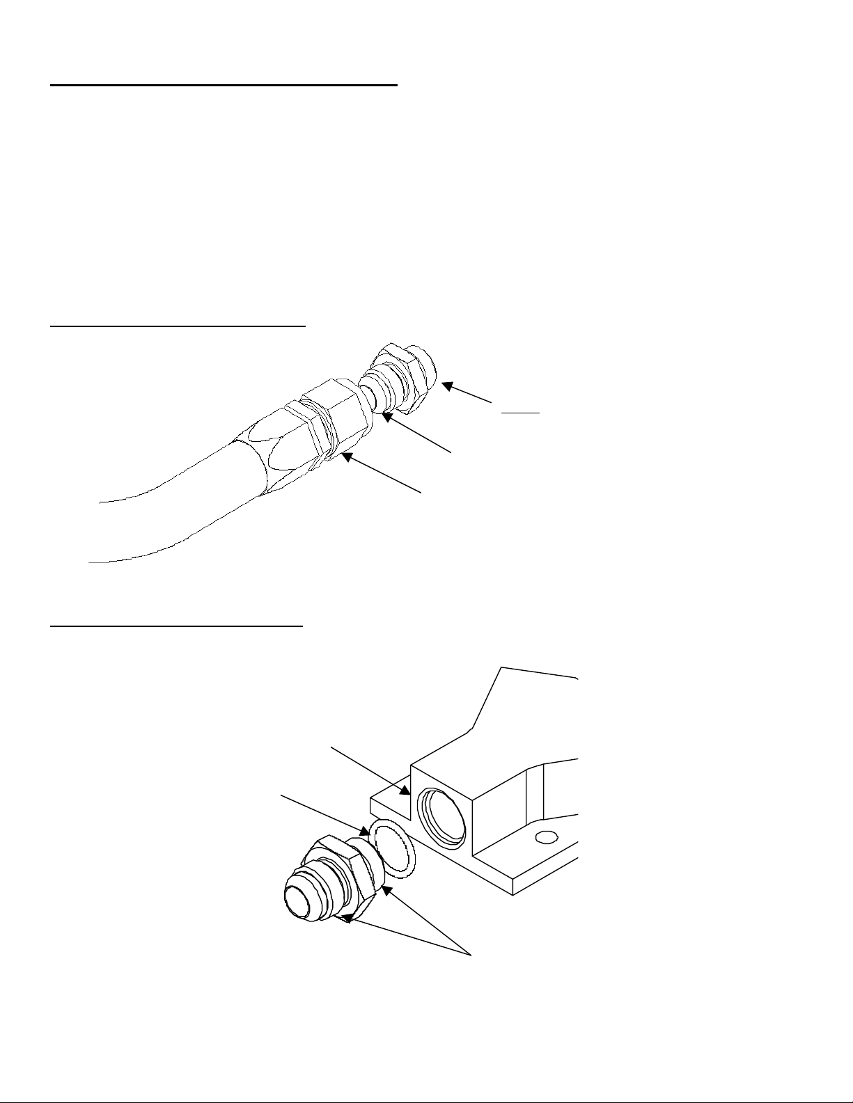
1-4. In the kit find one AN-10 to AN-08 cutoff union, one AN-10 to AN-06 cutoff fitting, two AN-10 o-rings, one AN-08 o-
ring, and one AN-06 o-ring. Install each of the four o-rings on each of the appropriate ends of the fittings.
1-5. Install each of the two fittings into each end of the provided Aeromotive fuel pump.
1-6. Noting the appropriate flow directions, install the provided fuel filter, Aeromotive p/n 12301, on the fuel pump outlet
and the other fuel filter, Aeromotive p/n 12304, on the fuel pump inlet. If you get the two filters mixed-up, the 12304
filter will have a 100 micron stainless steel filter element inside, where as the 12301 will have a 10 micron paper filter
element inside.
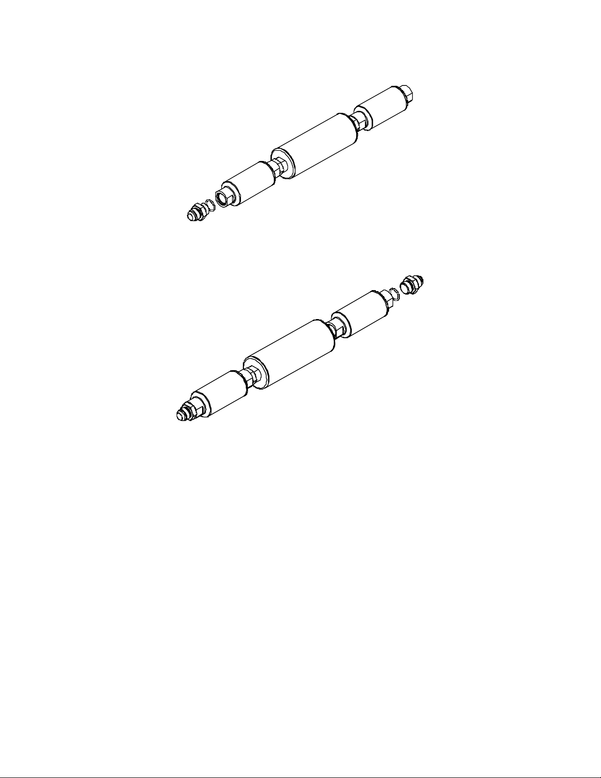
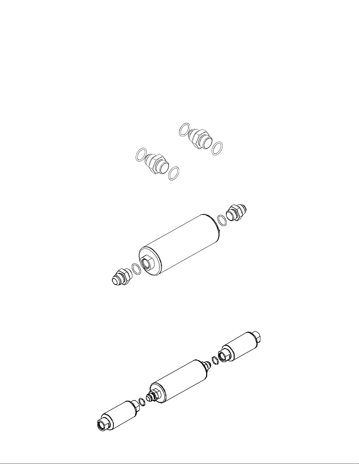
1-7. Install one of the supplied AN-10 o-rings on the cutoff side of the AN-10 to AN-08 reducer fitting and install on the inlet
side of the pump / filter assembly.
1-8. Install one of the supplied AN-10 o-rings on the AN-10 cutoff side of the AN-10 to AN-06 reducer union fitting, and
install the fitting on the outlet side of the pump / filter assembly.
1-9. Find a suitable mounting location for the above pump / filter assembly. Typical mounting locations include mounting
the fuel pump to the fuel tank shield or mounting to the inside of the frame rail. The fuel pump should be mounted as
close to the fuel tank as possible and as low as possible. Using the fuel pump mounting clamps as a guide, mark the
four pump mounting holes. Ensure there are no obstructions behind the mounting surface and drill four ¼” mounting
holes.
Note: Be sure to route all fuel lines clear of any moving suspension or drivetrain components and any exhaust
components! Protect fuel lines from abrasion and road obstructions or debris.
1-10. If you are using the plastic fuel tank shield for mounting your fuel pump, secure the fuel pump to the plastic fuel
tank shield by installing four ¼” carriage bolts (not included) from the inside of the fuel tank shield, through the fuel
tank shield and through the fuel pump mounting holes. Install four flat washers and nuts on the bolts and tighten.
Inspect the inside of the plastic fuel tank shield for any sharp edges that could puncture the fuel tank. If any sharp
edges are found, correct before proceeding.
1-11. If you are mounting the fuel pump in some other fashion, secure the fuel pump to the mounting surface using four
¼” bolts, nuts, and lock washers (not provided).
Note: Be sure to route all fuel lines clear of any moving suspension or drivetrain components and any exhaust
components! Protect fuel lines from abrasion and road obstructions or debris.
1-12. Using the two supplied AN-08 hose ends as a guide, measure the length of AN-08 steel braided line needed to
connect your fuel tank sump or fuel cell outlet to the fuel pump / filter assembly inlet.
1-13. Cut and assemble the steel braided hose and hose ends as shown in Section 3.
 Loading...