

Aeromotive 17130 User Manual
AEROMOTIVE
Part # 17130
86-95 Mustang 5.0L Fuel System Kit
INSTALLATION INSTRUCTIONS
CAUTION:
Installation of this product requires detailed knowledge of automotive systems and
repair procedures. We recommend that this installation be carried out by a qualified
automotive technician.
Installation of this product requires handling of gasoline. Ensure you are working in a
well ventilated area with an approved fire extinguisher nearby. Extinguish all open flames,
prohibit smoking and eliminate all sources of ignition in the area of the vehicle before
proceeding with the installation.
When installing this product, wear eye goggles and other safety apparel as needed to
protect yourself from debris and sprayed gasoline
WARNING!
The fuel system is under pressure. Do not open the fuel system until the pressure has
been relieved. Refer to the appropriate vehicle service manual for the procedure and
precautions for relieving the fuel system pressure
Aeromotive system components are not legal for sale or use on emission controlled motor vehicles.
This kit contains the following parts:
1 ea P/N 18690 Cobra-Top Stealth Fuel Tank
1 ea P/N 16301 fuel pump wiring kit
1 ea 3ft length of 10-ga. Black wire
1 ea 25ft length of 10-ga. Red wire
1 ea 30-amp circuit breaker
1 ea 30-amp automotive relay
2 ea blue female blade connector
2 ea yellow female blade connector
5 ea yellow #10 stud ring connector
1 ea yellow 3/8” stud ring connector
6 ea tie-wraps
26 ft AN-06 stainless steel braided line
16 ft AN-08 stainless steel braided line
6 ea P/N 15650 AN-06 straight hose-end
1 ea P/N 15651 AN-06 45-degree hose-end
5 ea P/N 15652 AN-06 90-degree hose-end
2 ea P/N 15653 AN-08 straight hose-end
2 ea P/N 15655 AN-08 90-degree hose-end
1 ea P/N 12301 Filter 10-Micron Paper
.
.
1 ea P/N 13109 A1000-06 Fuel Pressure Regulator
1 ea P/N 14101 Ford 5.0L Billet Fuel Rails
1 ea P/N 15673 AN-08 to 2-AN-06 Y-block
2 ea ¼” flat washers
2 ea ¼-20 nyloc nuts
2 ea ¼-20 x 1” carriage bolts
12 ea tie-wraps
3 ea AN-06 o-ring
6 ea AN-08 o-ring
2 ea AN-10 o-ring
1 ea P/N 15602 AN-06 male/male flare union
5 ea P/N 15605 ORB-08 to AN-06 male flare
3 ea P/N 15606 ORB-06 to AN-06 male flare
1 ea P/N 15607 ORB-08 to AN-08 male flare
2 ea P/N 15610 ORB-10 to AN-08 male flare
12 ea cushioned clamps
12 ea self drilling screws
1 ea P/N 12305 2” billet filter bracket
1 ea P/N 15633 0-100psi fuel pressure gauge
The following steps are typical of most installations:
with O
-
ring added into the filter
.
Section 1 - Fuel Tank Installation / Electrical wiring
Section 2 – Fuel Rail Installation
Section 3 – Fuel Regulator Installation and Fuel Line Plumbing
Section 4 – Fuel Line Hose End Installation
Section 5 – Final Checks and System Start-up
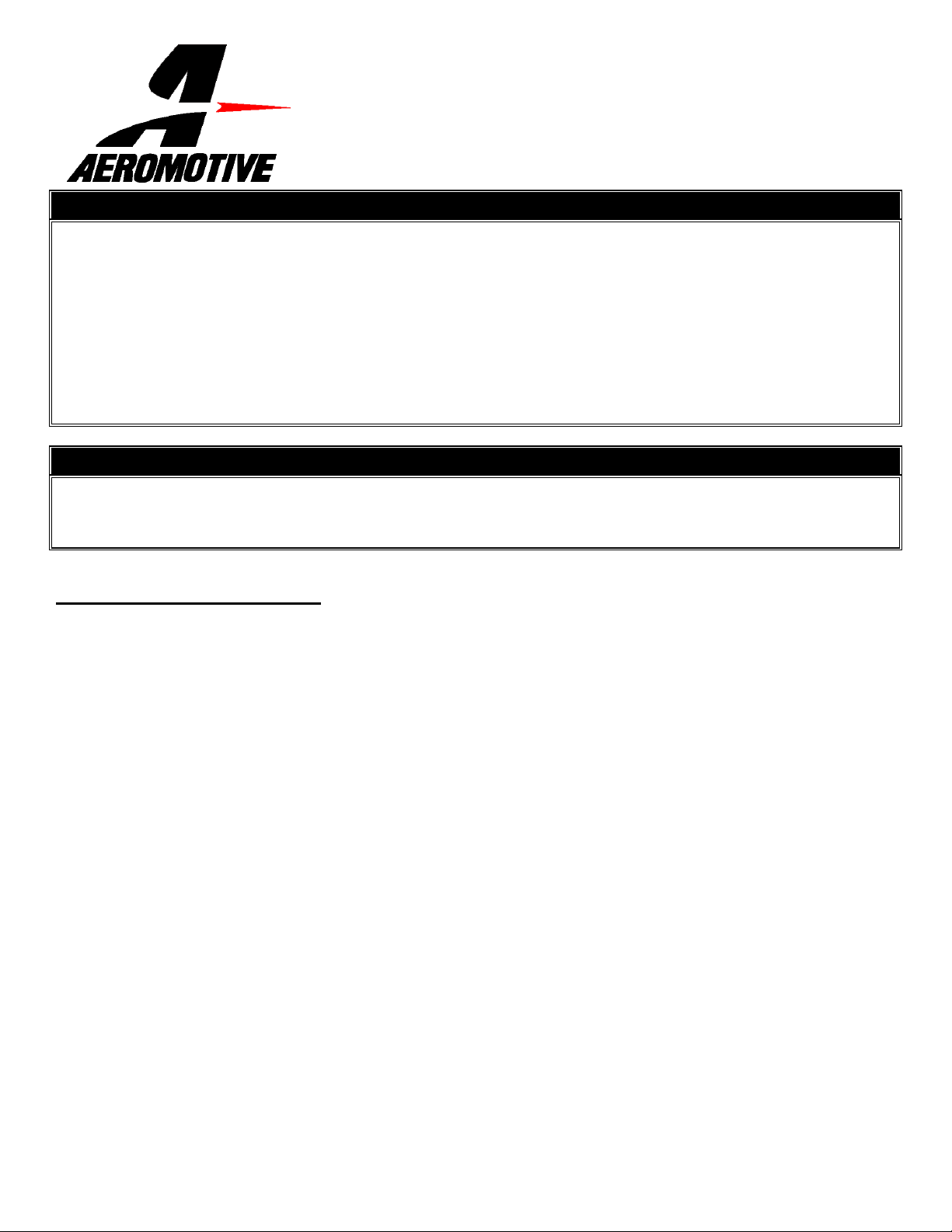
Typical hose end to fitting connection:
Do not connect hose end to cutoff side of union!
Connect hose end to 37-degree flare side of union.
Hose End
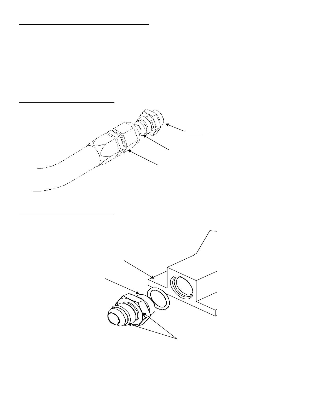
Typical o-ring sealed port connection:
O-ring sealed AN style port
O-ring
(Install on union fitting between back of
threads and face of hex nut.)
Typically the ORB (O-ring) side of the union is
installed in the port, leaving the 37-degree flare
side for your hose end connection. In some
cases you’ll install an O-ring on the flare side of
the fitting and use it as a union.
For example, in some systems an ORB to Flare
fitting is used to connect the fuel pump and filter
together, in which case you always install the
ORB side into the fuel pump and the flare side
Section 1 - Fuel Tank Installation:
1-1. Once the engine has been allowed to cool, disconnect the negative battery cable and relieve the fuel system pressure.
1-2. Raise the vehicle and support it with jack stands.
1-3. Referring to the appropriate vehicle service manual for instructions, drain, disconnect any electrical and fuel
component connections and remove the OEM fuel tank. The removal of the vehicles exhaust system may be
necessary for fuel tank removal.
1-4. Once the OEM fuel tank has been removed, remove the plastic fuel tank shield from the bottom of the tank. Before
transferring the shield to the new Aeromotive tank, attach the 12305 filter bracket to the front side of the shield with the
two supplied carriage bolts, nuts and washers (bracket will be placed facing the rear differential cover) FIGURE 1-1.
Insert the 12301 filter into the bracket and tighten the socket head cap screw to secure the filter. Screw the two 15610
fittings with o-rings on the ORB-10 port side into each end of the filter.
FIGURE 1-1
1-5. Remove the Aeromotive fuel pump assembly to gain access to the inside of the tank. Set fuel pump assembly to the
side for later use.
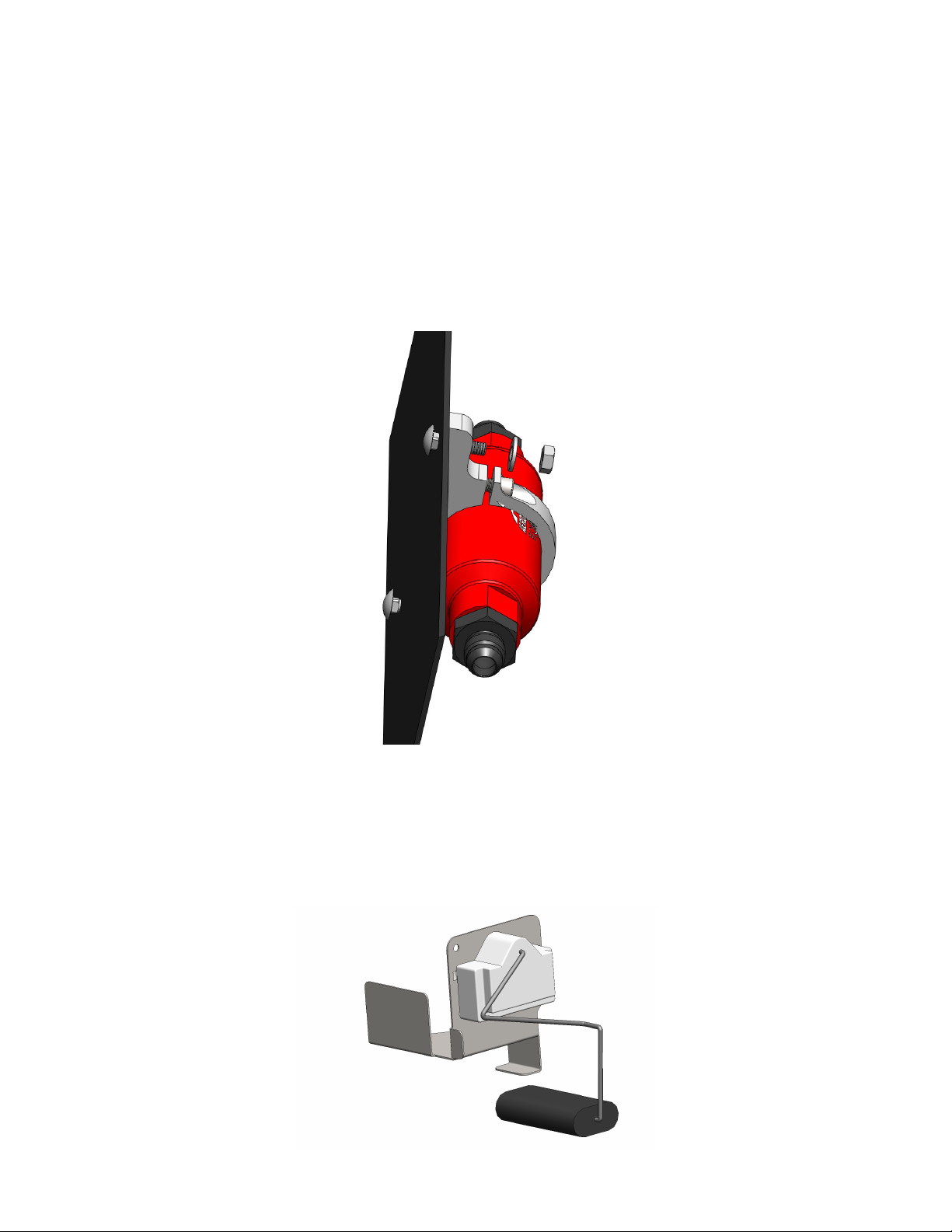
1-6. From the old OEM fuel tank, remove the filler neck rubber grommet, fuel level sender, vent and vent grommet, and
wiring harness. Inspect all parts for damage, if none found, reinstall in the new Aeromotive tank. If any of the OEM
components are damaged replacement parts are available through your local Ford dealer or auto parts store. Use
FIGURE 1-2 to install the factory fuel level sender onto the provided fuel level bracket.
FIGURE 1-2
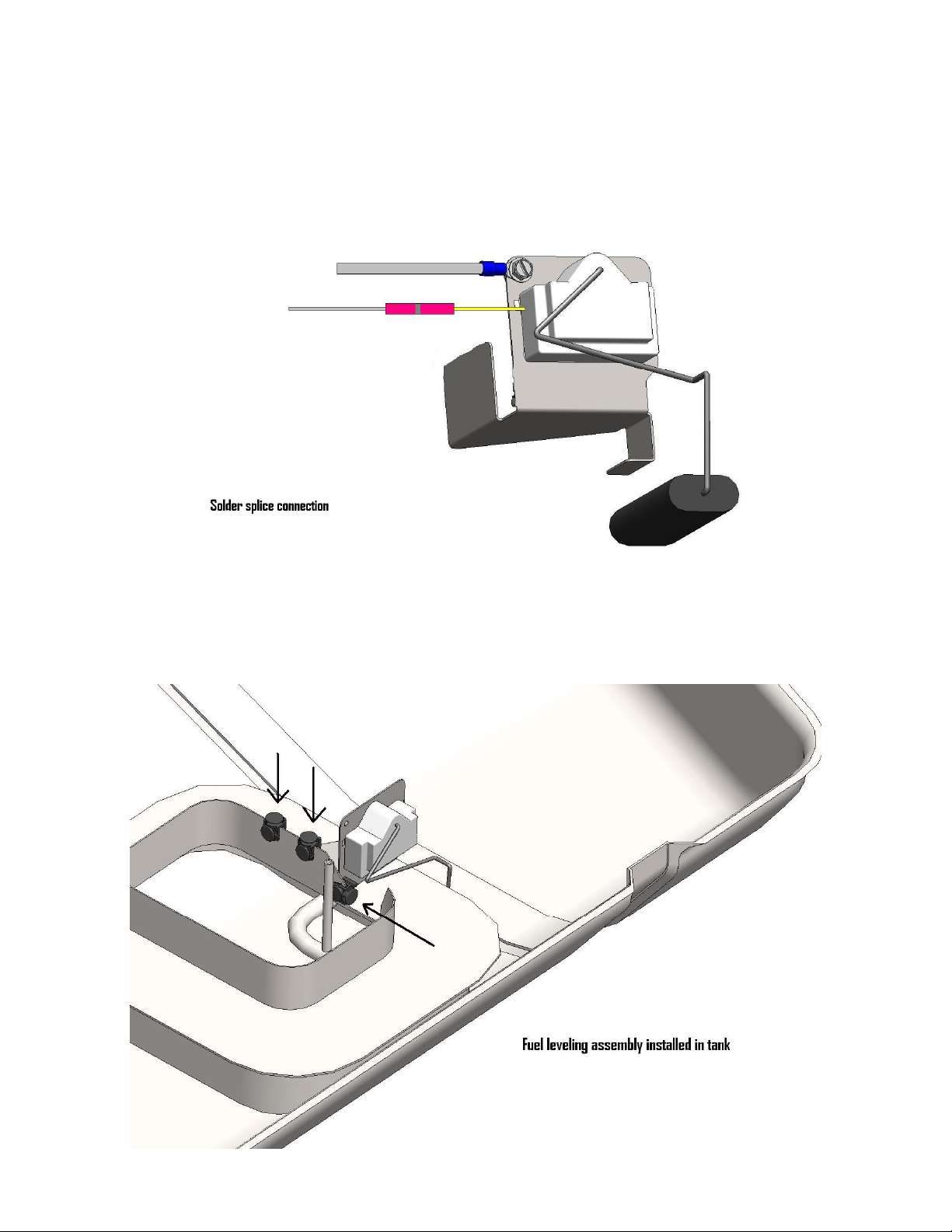
1-7. Before placing the fuel level sender assembly in the tank, attach the two level sending unit wires on the Stealth pump
to the fuel level sender assembly. Using the red solder/splice and a heat gun or small butane torch, connect and
solder/shrink wrap one of the wires from the fuel pump to the wire on the sending unit itself and mark the
corresponding terminal on the outside of the pump with a black marker or masking tape. Next, crimp the provided
ring connector on the remaining wire and attach the ring connector to the bracket with the self-tapping screw.
See FIGURE 1-3
FIGURE 1-3
1-8. With the pump resting on top of the fuel tank, position the fuel level sender assembly into the tank as shown in
FIGURE 1-4 With the fuel level sender bracket and the baffle walls butted up against each other. Push the provided
edge clips into position to secure the fuel level sending unit bracket to the top of the baffle inlet wall.
FIGURE 1-4
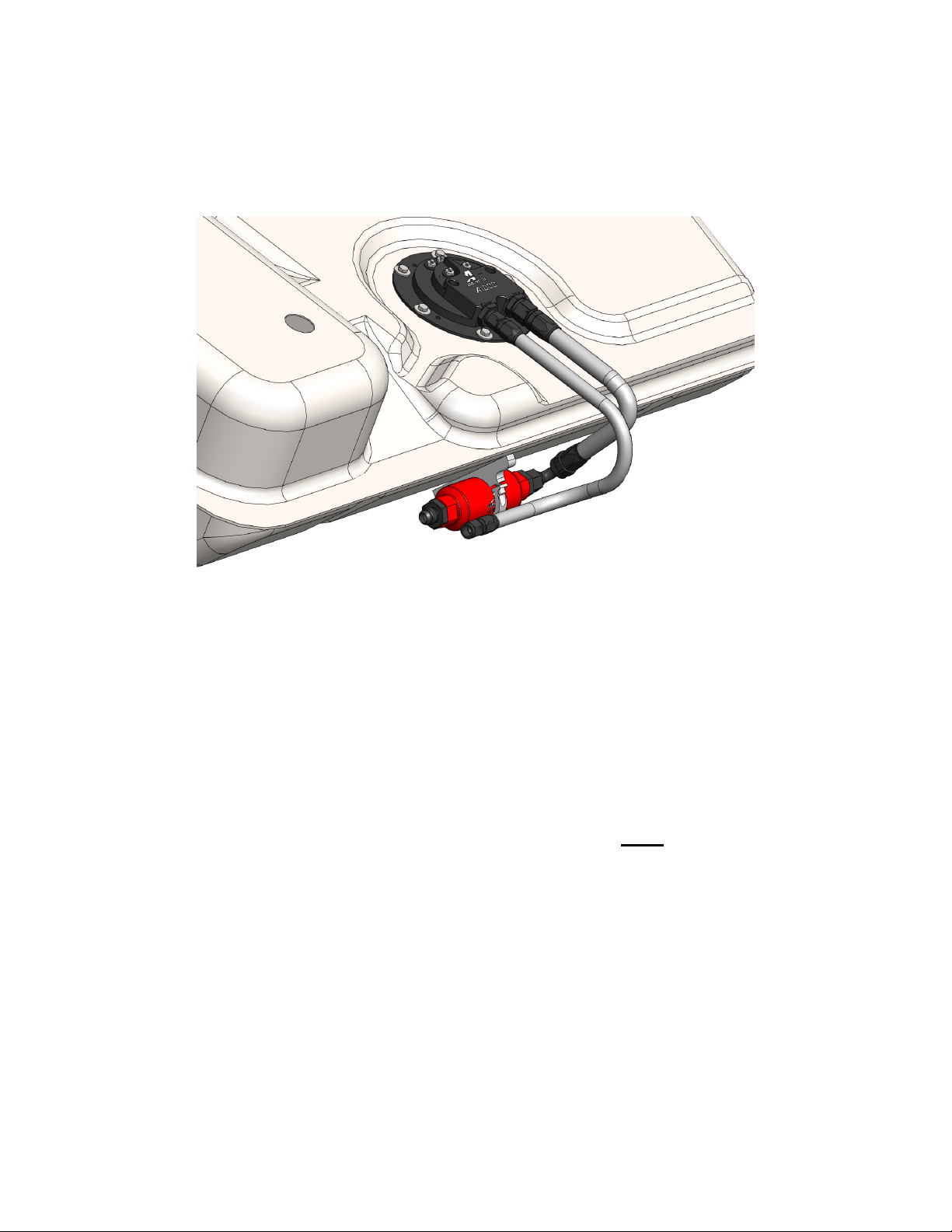
1-9. Now the fuel tank is ready for your Aeromotive fuel pump assembly. Place one 15607 fitting with o-ring into the outlet
port and one 15605 fitting with o-ring in the return port at this time.
1-10. Place the fuel pump sealing gasket on top of the tank mounting ring and position the fuel pump in the tank with the
outlet/return ports facing forward (toward the front of the car). Use the supplied 6 bolts and washers to secure the
pump assembly to the tank. Place the lower tank shield onto the bottom of the new Aeromotive tank at this time.
Assemble a small section of AN-08 hose with straight hose-end on one side and 90-degree hose-end on the other.
Route from the pump outlet to the fuel filter inlet. Next, assemble a 1-2 foot section of AN-06 line with straight hoseends at each end. Connect one end of the AN-06 line to the return port of the pump. FIGURE 1-5
FIGURE 1-5
1-11. Before placing the fuel tank back in the car, install the small ring terminals provided onto the 10-gauge black and
red wires and connect them to the Stealth Pump (+) power and (-) ground terminals. Note: Hold the ring terminal/wire
firmly while tightening the terminal nuts and do not over tighten to avoid over- rotating the electrical bulkheads.
1-12. At this time, locate the factory fuel tank wiring harness underneath the trunk floor and, measuring 1-2 inches back
from the plug, cut the 4 wires and remove the plug. Redirect the two wires formerly connected to the OEM pump, to
the new fuel pump relay (provided). Install the small ring terminals provided on the remaining two wires and prepare
them for connection to the fuel level sending unit terminals on the Stealth Fuel Pump.
1-13. Find a suitable place to mount the provided, heavy duty fuel pump relay, it is typically mounted near the end of the
fuel tank harness, where the factory plug was removed in step 11-12 above. (Never mount the relay inside of the
fuel tank or next to fuel tank vents!). Insure the new relay and any associated parts are clear of the exhaust, any
moving suspension or drivetrain components and any possible road obstructions or debris.
1-14. Attach the OEM fuel pump wires (These typically are the red and black wires from the OEM wiring harness going to
the fuel tank) to relay terminals 85 and 86 using the supplied blue female blade connectors (See Figure 1-6 Below).
Note: Be sure to route all electrical wires clear of any moving suspension or drivetrain components, and any
exhaust components! Protect wires from abrasion and road obstructions or debris.
1-15. Find a suitable location for mounting the supplied 25-amp circuit breaker. For optimal circuit protection, the circuit
breaker needs to be mounted as close to the supply point, either the battery or alternator charging stud, as possible.
1-16. Route the supplied 10-ga red wire from the circuit breaker near the battery to the relay and terminate it with one of
the yellow, female blade connectors supplied. Connect it to terminal number 30 on the relay. At the circuit breaker
end of this wire install one of the yellow #10 ring connectors and install it one of the two studs on the circuit breaker.
Note: Be sure to route all electrical wires clear of any moving suspension or drivetrain components and any
exhaust components! Protect wires from abrasion and road obstructions or debris.
 Loading...