

Aeromotive 14145 User Manual
AEROMOTIVE
Part # 14145
07 Ford 5.4L GT500 Shelby Mustang
Fuel Rail Kit
INSTALLATION INSTRUCTIONS
CAUTION:
Installation of this product requires detailed knowledge of automotive
systems and repair procedures. We recommend that this installation be carried
out by a qualified automotive technician.
Installation of this product requires handling of gasoline. Ensure you are
working in a well ventilated area with an approved fire extinguisher nearby.
Extinguish all open flames, prohibit smoking and eliminate all sources of ignition
in the area of the vehicle before proceeding with the installation.
When installing this product, wear eye goggles and other safety apparel as
needed to protect yourself from debris and sprayed gasoline.
WARNING!
The fuel system is under pressure. Do not open the fuel system until the
pressure has been relieved. Refer to the appropriate vehicle service manual for
the procedure and precautions for relieving the fuel system pressure.
Aeromotive system components are not legal for sale or use on emission controlled motor
vehicles.
This kit contains the following parts
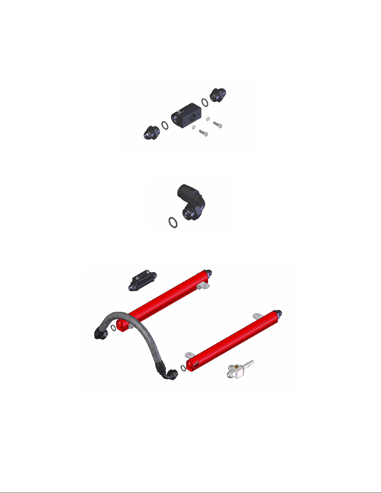
1ea p/n 14144 Ford 5.4L Shelby Mustang Fuel Rails
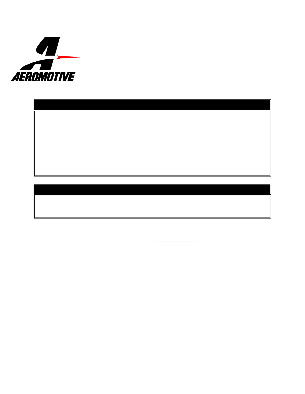
1ea p/n 15115 Fuel Sensor Adapter
2ea 10-24 x 5/8” Socket Head Cap Screws
2ea #10 Lock Washers
1ea p/n 15116 3/8” Quick Connect AN-08 Tee Fitting
4ea p/n 15607 –8/-8AN Cutoff Tapered Flare Fitting
:
Supplies needed:
Vehicle service manual
Fuel injector replacement O-rings
Light oil
Solvent parts cleaner
Clean shop towels
1ea p/n 15653 -8 Str. Hose End
1ea p/n 15654 –8 45-Deg Hose End
4ea p/n 15655 -8 90-Deg Hose End
2ea p/n 15665 –8 90-Deg Male ORB Hose End
10ft –8 Stainless Steel Braided Fuel Line
6ea AN-08 O-Ring

The following steps are typical of most installations:
1. Once the engine has been allowed to cool, disconnect the negative battery cable and relieve fuel
system pressure, referring to the appropriate vehicle service manual for the procedure on doing so.
2. Note the location of and remove any vacuum or electrical connections on the air breather duct and
throttle body. Loosen the clamp holding the air duct on the throttle body, unclip the air breather box lid
and remove the air duct.
3. Remove the 4 screws that hold the throttle body elbow and throttle body to the upper intake.
4. Check for any dirt or debris around the fuel injectors. If any is evident, wash it off with some solvent
parts cleaner or wipe it off with a clean shop towel.
5. Disconnect the electrical connector at each injector, making note of the location of each.
6. Ensure that the fuel system pressure has been relieved per the factory service manual.
7. Disconnect the supply fuel line from the OEM fuel rails. Place clean shop towels around the open fuel
line to catch any gasoline that may drip out and to prevent any dirt from entering the fuel lines.
8. Remove the 4 bolts that attach the fuel rail to the intake.
9. Place clean shop towels around the injectors to catch any gasoline that may be spilled during their
removal. Remove the injectors from the manifold by gently pulling upward on the fuel rail / injector
assembly. Keep all injectors connected to the fuel rails. If an injector does pull out of the fuel rail, it
may spill a large amount of fuel.
10. Carefully remove the fuel injectors from the OEM fuel rail.
11. Remove the old o-rings from the fuel injectors, inspect the injectors for any dirt or debris and clean if
needed. It is suggested that the old o-rings be replaced, contact your local parts dept.
12. Coat the new fuel injector o-rings with a light oil to ease installation.
13. Carefully install the new fuel injector o-rings on the injectors.
14. Place a thin coat of light oil in the fuel rail fuel injector bores and in the lower intake manifold injector
bores to help prevent cutting the o-rings during installation.
15. Carefully place the fuel injectors in the fuel rails. Position the electrical connector on each fuel injector
to the opposite side of the fuel rail as the mounting bracket.
16. Install the fuel rails being careful not to cut any of the o-rings during installation, reinstall and tighten
the fuel rail mounting bolts.
17. Install one AN-08 o-ring on each of the four AN-8 cutoff tapered flare fittings.
18. Thread the o-ring side of two AN-08 cutoff fittings in the rear of each fuel rail.
19. Thread the o-ring side of the remaining two AN-08 cutoff fittings in each side of the Aeromotive fuel
pressure sensor adapter, p/n 15115.
20. Remove the OEM fuel pressure sensor from the factory fuel rail and install on the Aeromotive fuel
sensor adapter block, p/n 15115, using the provided screws and washers.
21. Install one AN-08 o-ring on each of the two AN-08 90-Deg Male ORB hose ends.
22. Connect each of the two AN-08 90-Deg Male ORB hose ends to the front of each fuel rail. Plan a
route between the two hose ends over the top of the supercharger, taking into account hood
clearance, measure the lengths of fuel line needed. See section titled Hose and Fitting Assembly for
fuel line assembly instructions. Once the hoses are assembled, ensure there is no debris in the
hose and install them.
23. Reconnect the fuel pressure sensor on the Aeromotive fuel sensor mounting block, p/n 15115, to the
wiring harness and position as shown above.
24. Connect the Aeromotive 3/8 Quick connect tee fitting, p/n 15116, to the factory fuel supply line and
position as shown above.
 Loading...