

Aeromotive 14139 User Manual
AEROMOTIVE
Part # 14139
98-02 LS-1 F-Body
Fuel Rail Kit
INSTALLATION INSTRUCTIONS
CAUTION:
Installation of this product requires detailed knowledge of automotive
systems and repair procedures. We recommend that this installation be carried
out by a qualified automotive technician.
Installation of this product requires handling of gasoline. Ensure you are
working in a well ventilated area with an approved fire extinguisher nearby.
Extinguish all open flames, prohibit smoking and eliminate all sources of ignition
in the area of the vehicle before proceeding with the installation.
When installing this product, wear eye goggles and other safety apparel as
needed to protect yourself from debris and sprayed gasoline.
WARNING!
The fuel system is under pressure. Do not open the fuel system until the
pressure has been relieved. Refer to the appropriate vehicle service manual for
the procedure and precautions for relieving the fuel system pressure.
Aeromotive system components are not legal for sale or use on emission controlled motor
vehicles.
Special tools needed:
Fuel supply line quick disconnect tool
This kit contains the following parts
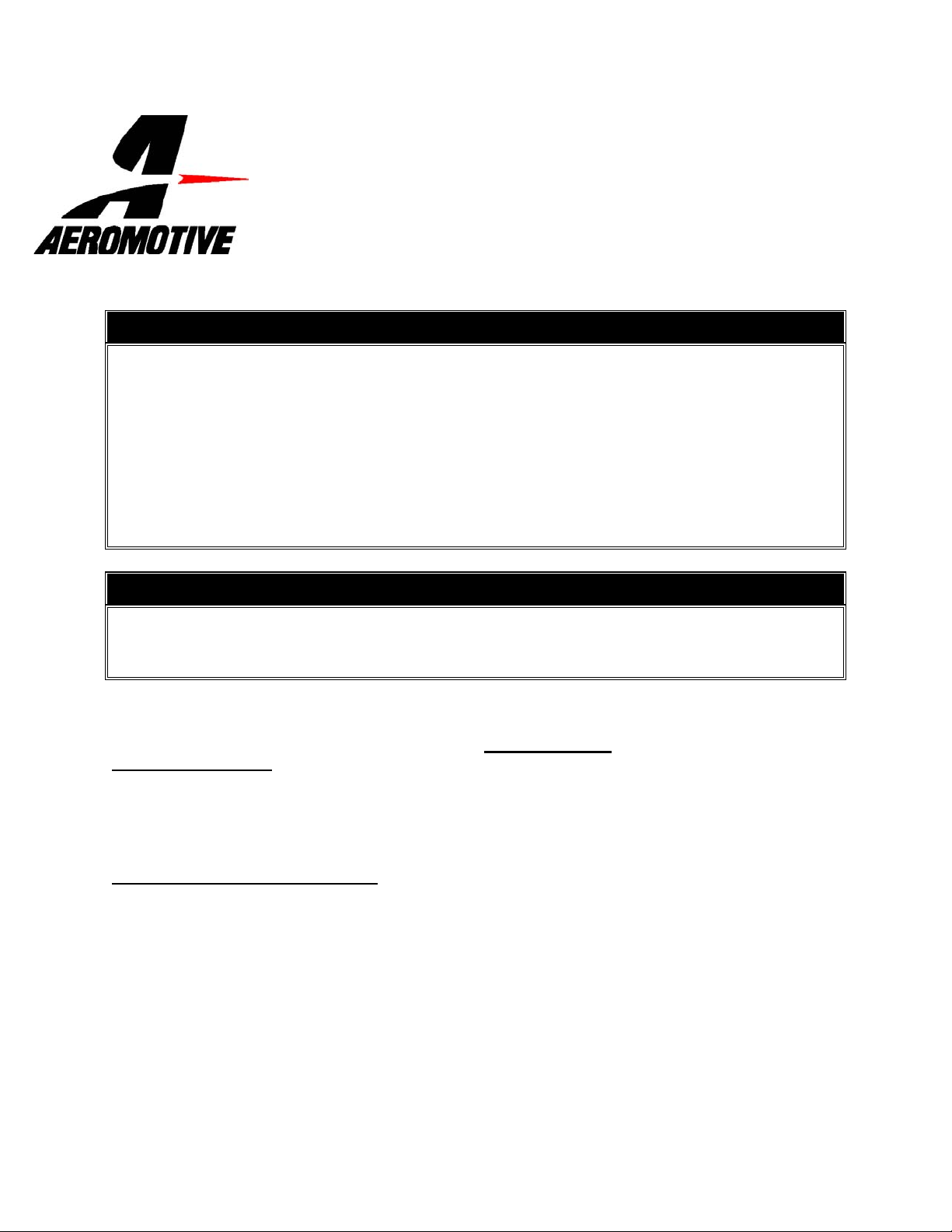
1ea p/n 14106 GM LS1 Fuel Rails
1ea p/n 15116 Supply Adapter Tee Fitting
2ea p/n 15607 –8/-8AN Cutoff Tapered Flare Fitting
2ea p/n 15605 –8/-6 Reducer Union Fitting
2ea p/n 15652 -6 90-Deg Hose End
:
Supplies needed:
Vehicle service manual
Fuel injector replacement O-rings
Light oil
Solvent parts cleaner
Clean shop towels
1ea p/n 15654 –8 45-Deg Hose End
3ea p/n 15655 -8 90-Deg Hose End
2ft –6 Stainless Steel Braided Fuel Line
4ft –8 Stainless Steel Braided Fuel Line
4ea AN-08 O-Ring

The following steps are typical of most installations:
1. Once the engine has been allowed to cool, disconnect the negative battery cable and relieve fuel
system pressure, referring to the appropriate vehicle service manual for the procedure on doing so.
2. Note the location of and remove any vacuum lines connected to the upper intake manifold and
position them out of the way.
3. Check for any dirt or debris around the fuel injectors. If any is evident, wash it off with some solvent
parts cleaner or wipe it off with a clean shop towel.
4. Disconnect the electrical connector at each injector, making note of the location of each.
5. Carefully relieve fuel system pressure per factory service manual.
6. Disconnect the supply fuel line from the OEM fuel rails. This line is attached by a special quick
disconnect fitting which requires a special tool for removal. Place clean shop towels around the open
fuel line to catch any gasoline that may drip out and to prevent any dirt from entering the fuel lines.
7. Remove the bolts that attach the fuel rail to the intake (Typically there are 4 of them).
8. Place clean shop towels around the injectors to catch any gasoline that may be spilled during their
removal. Remove the injectors from the manifold by gently pulling upward on the fuel rail / injector
assembly. Keep all injectors connected to the fuel rails. If an injector does pull out of the fuel rail, it
may spill a large amount of fuel.
9. Carefully remove the fuel injectors from the OEM fuel rail.
10. Remove the old o-rings from the fuel injectors, inspect the injectors for any dirt or debris and clean if
needed. It is suggested that the old o-rings be replaced, contact your local parts dept.
11. Coat the new fuel injector o-rings with a light oil to ease installation.
12. Carefully install the new fuel injector o-rings on the injectors.
13. Place a thin coat of light oil in the fuel rail fuel injector bores and in the lower intake manifold injector
bores to help prevent cutting the o-rings during installation.
14. Carefully place the fuel injectors in the fuel rails (depending on vehicle, placing the injectors in the
intake first might ease installation). Position the electrical connector on each fuel injector to the
opposite side of the fuel rail as the mounting bracket.
15. Install the fuel rails being careful not to cut any of the o-rings during installation.
16. Install one AN-08 o-ring on each of the two AN-8 cutoff tapered flare fittings and the two AN-08 / AN-
06 reducer fittings..
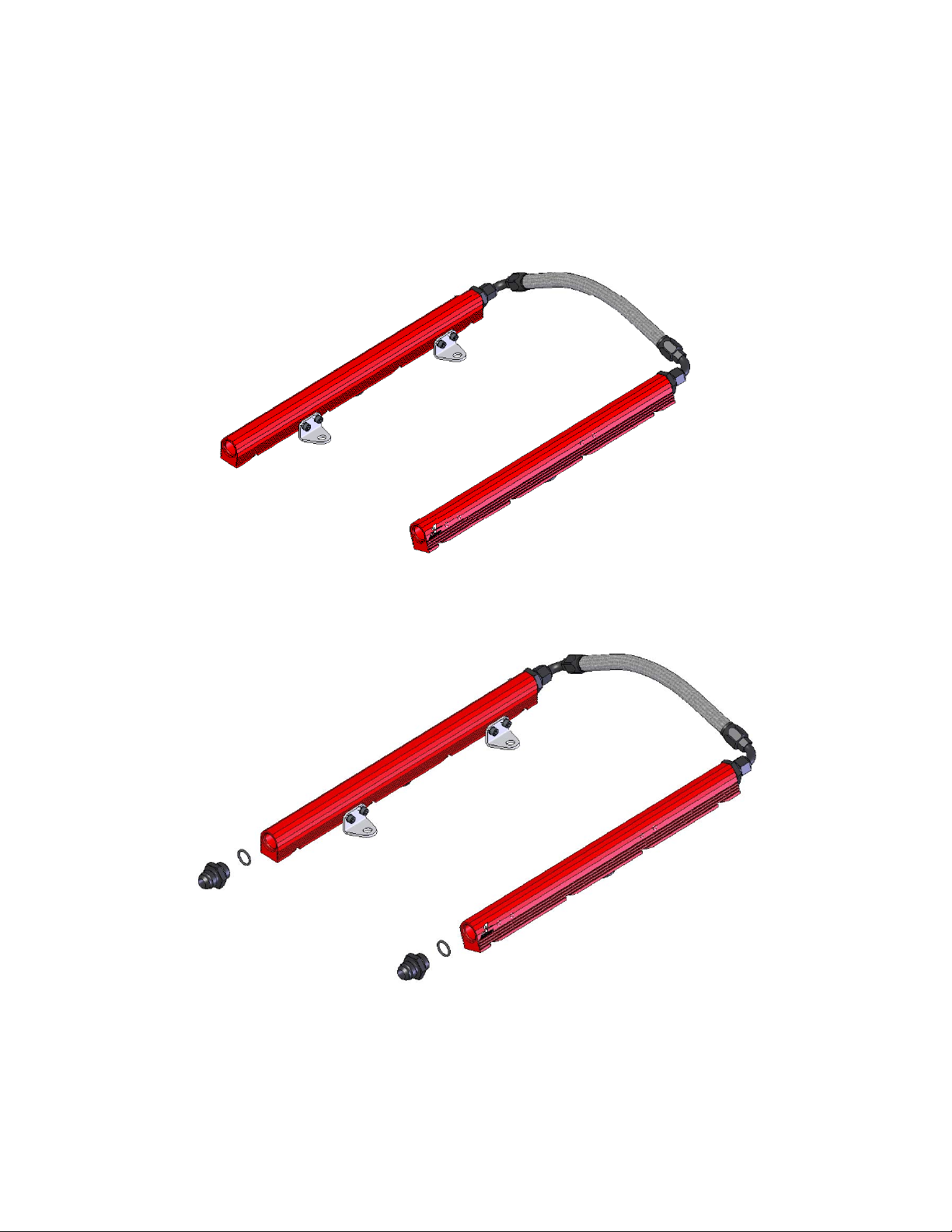
17. Thread the o-ring side of each two AN-08 /AN-06 reducer fittings in the rear of each fuel rail.
18. Connect each of the two AN-06 90-Deg hose ends to the rear of each fuel rail. Plan a route between
the two hose ends, measure the lengths of fuel line needed. See section titled Hose and Fitting
Assembly for fuel line assembly instructions. Once the hoses are assembled, ensure there is no
debris in the hose and install them
19. Thread the o-ring side of each two AN-08 cutoff tapered flare fittings in the front of each fuel rail.
 Loading...