

Aeromotive 14135 User Manual
AEROMOTIVE
Part # 14135
’04-‘06 Subaru WRX Fuel Rail Kit
INSTALLATION INSTRUCTIONS
CAUTION:
Installation of this product requires detailed knowledge of automotive
systems and repair procedures. We recommend that this installation be carried
out by a qualified automotive technician.
Installation of this product requires handling of gasoline. Ensure you are
working in a well ventilated area with an approved fire extinguisher nearby.
Extinguish all open flames, prohibit smoking and eliminate all sources of ignition
in the area of the vehicle before proceeding with the installation.
When installing this product, wear eye goggles and other safety apparel as
needed to protect yourself from debris and sprayed gasoline.
WARNING!
The fuel system is under pressure. Do not open the fuel system until the
pressure has been relieved. Refer to the appropriate vehicle service manual for
the procedure and precautions for relieving the fuel system pressure.
Aeromotive system components are not legal for sale or use on emission controlled motor vehicles.
When installing o-rings it is important to place a small amount of light oil on both the o-ring and
the mating surface to ease installation and prevent damaging the o-ring.
Special tools needed:
Fuel line quick disconnect tool
This kit contains the following parts
1ea p/n 14134 Subaru WRX 2.0L Fuel Rails
1ea p/n 13109 EFI Regulator
1ea p/n 15119 Supply Tee Adapter Fitting
2ea p/n 15635 AN-06 to 5/16” Barb Fitting
3ea p/n 15606 AN-6/AN-6 Cutoff Tapered Flare Fitting
1ea p/n 15607 AN-8/AN-8 Cutoff Tapered Flare Fitting
2ea p/n 15636 AN-8/AN-6 Banjo Fitting
4ea AN-06 O-Ring
2ea AN-08 O-Ring
4ea 5/8 Dia. Cushioned Cable Clamp
The following installation instructions are for a typical installation, for specific year and model
installation instructions please refer to your vehicles service manual.
:
Supplies needed:
Vehicle service manual
Fuel injector replacement O-rings
Light oil
Solvent parts cleaner
Clean shop towels
2ea p/n 15650 –6 Straight Hose End
1ea p/n 15651 –6 45-Degree Hose End
3ea p/n 15652 –6 90-Degree Hose End
1ea p/n 15653 –8 Straight Hose End
1ea p/n 15654 –8 45-Degree Hose End
1ea p/n 15655 –8 90-Degree Hose End
1ea p/n 15665 –8 90-Deg. Male ORB Hose End
10ft –6 Stainless Steel Braided Fuel Line
6ft –8 Stainless Steel Braided Fuel Line
3ft 5/16” 30R9 Fuel Injector Hose
3ft ¼” OD Vacuum Tubing

1. Once the engine has been allowed to cool, disconnect the negative battery cable, relieve
fuel system pressure and drain engine coolant, referring to the appropriate vehicle service
manual for the procedure on doing so.
2. First the factory manifold must be removed using the following steps, for specific details
and instructions refer to the factory service manual.
3. Remove the turbo intercooler (top mount only) and air intake duct.
4. Disconnect all the wiring harness connections, noting where each goes.
5. Remove the bolts holding accessories and brackets to the manifold.
6. Disconnect all vacuum lines from the manifold, noting where each goes.
7. Remove the tumbler valve bolts connecting them to the heads, keeping the intake bolted
to the top of the tumbler valve. In some cases it may be easier to remove the tumbler
valves from the intake manifold.
8. Disconnect the fuel lines from the fuel rail assembly located on the driver side by the
firewall, placing clean shop towels around the fuel lines to catch any gasoline that may be
spilled during their removal
9. Carefully lift off the intake manifold, tumbler valve, OE fuel rail assembly.
10. Remove the three bolts holding the OE fuel lines to the intake manifold.
11. Remove the four bolts holding the OE fuel rails to the tumbler valves.
12. Remove the OE fuel rail assembly from the intake manifold assembly, being careful not
to damage the fuel injector o-rings.
13. Place clean shop towels around the injectors to catch any gasoline that may be spilled
during their removal. Remove each of the injectors from the manifold by gently pulling
upward on each of the injectors.
14. Remove the old o-rings from the fuel injectors, inspect the injectors for any dirt or debris
and clean if needed. It is suggested that the old o-rings be replaced, contact your local
auto parts store for replacement o-rings.
15. Coat the new fuel injector o-rings with a light oil to ease installation.
16. Carefully install the new injector o-rings on the injectors.
17. Place a thin coat of light oil in the fuel rail injector bores to help prevent cutting the orings during installation.
18. Carefully place each of the fuel injectors in the corresponding fuel injector bore of the
Aeromotive fuel rails.
19. Place each of the Aeromotive fuel rail / injector assemblies onto each of the tumbler
valves, being sure to align the bottom of each injector with the injector bores in the
tumbler valve.
20. Reinstall the fuel rail mounting bolts and tighten.
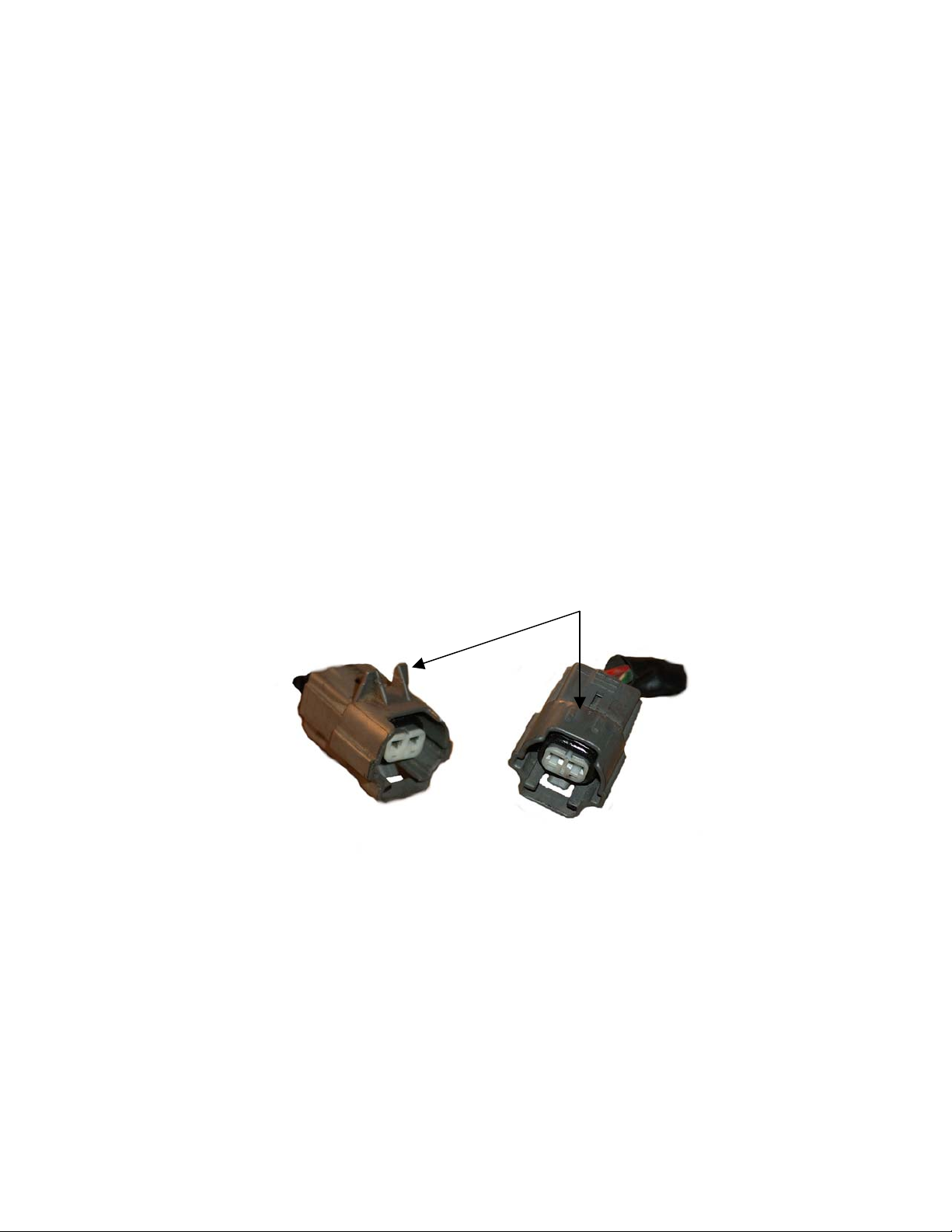
21. Orientate the fuel injectors such that the electrical connector is aligned with the outer
ends of the Aeromotive fuel rail.
22. It will be necessary to trim the alignment tabs off of the fuel injector wiring harness
connectors.
Trim alignment tab
23. Reinstall intake manifold assembly replacing gaskets and retightening bolts as outlined in
factory service manual.
24. Find suitable place in the vehicle’s engine compartment to mount the Aeromotive
regulator, typically on or near the passenger side strut tower. Using the supplied
mounting bracket as a template, mark the bracket mounting holes and drill to accept a
#10 screw.
25. With the bracket attached to the regulator, mount the bracket and regulator to the vehicle
using two #10 screws, nuts and lock washers.
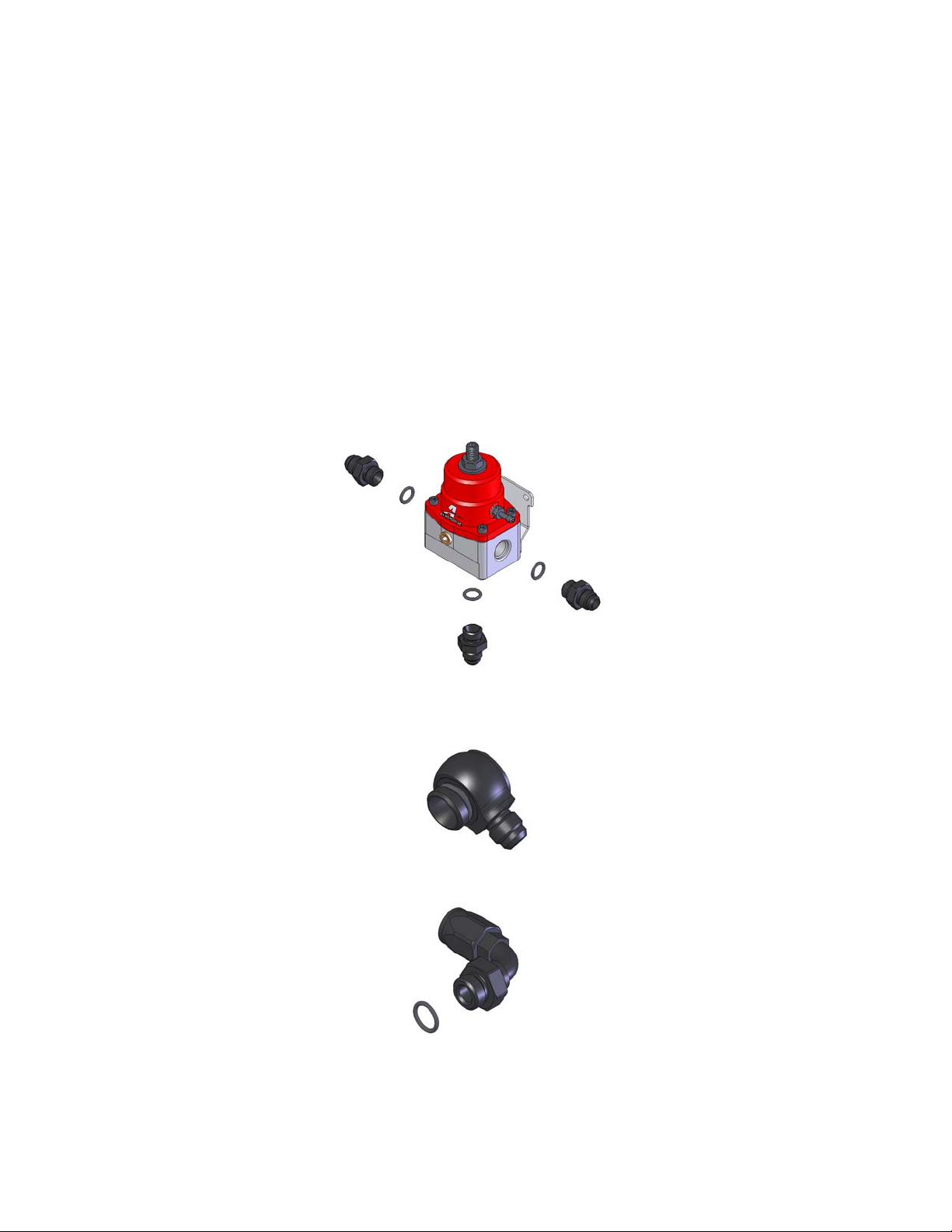
26. Install one AN-06 o-ring on each of the three AN-06 cutoff tapered flare fittings. Thread
the side of the AN-06 cutoff tapered fitting with the o-ring into each of the three AN-06
ports on the regulator.
27. Locate the two 90-Degree AN-08 to AN-06 Banjo fittings and insure that an AN-08 Oring is installed on the AN-08 Side of each.
28. Install one AN-08 o-ring on the AN-8 90-degree male ORB hose ends.

29. Thread the o-ring side of one of the AN-08 to AN-06 Banjo fittings into the rear port and
thread the AN-08 90-degree male ORB hose end in the front port of the passenger side
fuel rail.
30. Reinstall the passenger side “Fuel Pipe Protector” to insure that the rail and fittings have
adequate clearance.
31. Install one AN-08 o-ring on the AN-08 cutoff tapered flare fitting.
 Loading...