

Aeromotive 13351 User Manual

AEROMOTIVE Part # 13301 & 13351
INSTALLATION INSTRUCTIONS
CAUTION:
Installation of this product requires detailed knowledge of automotive
systems and repair procedures. We recommend that this installation be carried
out by a qualified automotive technician.
Installation of this product requires handling of gasoline. Ensure you are
working in a well ventilated area with an approved fire extinguisher nearby.
Extinguish all open flames, prohibit smoking and eliminate all sources of ignition
in the area of the vehicle before proceeding with the installation.
When installing this product, wear eye goggles and other safety apparel as
needed to protect yourself from debris and sprayed gasoline.
WARNING!
The fuel system is under pressure. Do not open the fuel system until the
pressure has been relieved. Refer to the appropriate vehicle service manual for
the procedure and precautions for relieving the fuel system pressure.
NOTE: Testing the enclosed regulator by applying air pressure or vacuum to the vacuum port with a handheld pump will yield poor results, due to the slight air leakage through the adjustment screw threads. This
minute leakage, which is typical of all adjustable fuel pressure regulators, does not, in any way, affect the
performance of the regulator.
The enclose Aeromotive regulator utilizes four 3/8 NPT pipe thread inlet/outlet ports and one 3/8NPT pipe thread bypass port. In order to use the enclosed regulator in your vehicle’s fuel system,
you must install the necessary adapter fittings, high pressure fuel lines and/or fuel injector rails to
adapt your system to the configuration and ports of this regulator. The following instructions
assume that your fuel system has already been configured for use with this regulator.
Aeromotive system components are not legal for sale or use on emission controlled motor vehicles.
Performance Specifications: Model 13301
Outlet Fuel Pressure, adjustable 3-20 psi low pressure spring
20-65 psi high pressure spring
Max Pump Flow Rate 250 GPH
Inlet / Outlet ports 4ea. 3/8-NPT
Bypass port (located at bottom of regulator) 1ea. 3/8-NPT
Fuel Compatibility Gasoline only
(installed from factory)
The following steps are typical of most installations:
1. Once the engine has been allowed to cool, disconnect the negative battery cable and relieve the fuel
system pressure.
2. Remove any cosmetic covers necessary to allow access to the fuel pressure regulator.
3. Remove the vacuum line from the regulator.
4. Place shop towels around the regulator to catch any gasoline that is spilled during this step of the
installation. Remove any regulator mounting hardware and connecting fuel lines, then carefully
remove the regulator.
5. Find a suitable place in the vehicle’s engine compartment to mount the Aeromotive regulator. Using
the supplied mounting bracket as a template, mark the bracket mounting hole and drill to accept
mounting bolt.
6. Determine approximate fuel pressure your system will require. If your fuel pressure requirement is
between 3 and 20 psi, the factory installed regulator spring is the proper spring. If your fuel pressure
requirement is between 20 and 65 psi, insure the pressure adjustment set screw is backed out all the
way, remove the 4 cover screws and cover, remove the factory installed spring, replace it with the high
pressure spring, and reassemble the regulator.
7. With the bracket attached to the regulator, mount the regulator to the vehicle.
8. Attach the fuel supply line(s) to the regulator using any of the 3/8-NPT ports located around the
perimeter of the regulator. Install 3/8-NPT pipe plugs into any of the unused regulator inlet ports.
Please note that these ports are pipe threads and will require the use of a pipe thread sealant.
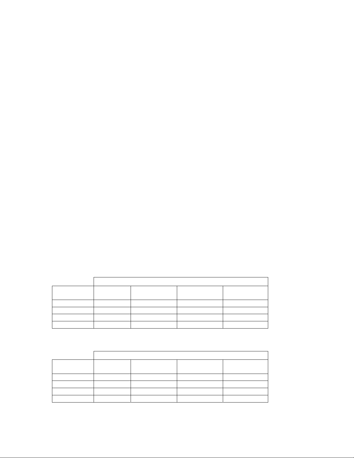
9. Attach the fuel return line to the 3/8-NPT port located on the bottom of the regulator. Use the chart
below to determine the minimum recommended return line size for your system. Please note that
these ports are pipe threads and will require the use of a pipe thread sealant.
Regulator with 3-20 psi spring
Fuel Line ID Chart
Fuel Pump Free Flow Rating (GPH)
Return Line
Length (ft.)
0-5 feet
5-10 feet
10-15 feet
15-20 feet
1 to 60
GPH
3/8” 3/8” 1/2” 1/2”
3/8” 1/2” 1/2” 5/8”
3/8” 1/2” 5/8” 3/4”
1/2” 1/2” 5/8 3/4”
60 to 120
GPH
120 to 180
GPH
180 to 250
GPH
Regulator with 20-65 psi spring
Fuel Line ID Chart
Fuel Pump Free Flow Rating (GPH)
Return Line
Length (ft.)
0-5 feet
5-10 feet
10-15 feet
15-20 feet
1 to 60
GPH
3/8” 3/8” 3/8” 3/8”
3/8” 3/8” 3/8” 3/8”
3/8” 3/8” 3/8” 1/2”
3/8 3/8” 3/8” 1/2“
60 to 120
GPH
120 to 180
GPH
180 to 250
GPH
 Loading...