

Aeromotive 13224 User Manual
AEROMOTIVE
Part # 13224
INSTALLATION INSTRUCTIONS
CAUTION:
Installation of this product requires detailed knowledge of automotive
systems and repair procedures. We recommend that this installation be carried
out by a qualified automotive technician.
Installation of this product requires handling of gasoline. Ensure you are
working in a well ventilated area with an approved fire extinguisher nearby.
Extinguish all open flames, prohibit smoking and eliminate all sources of ignition
in the area of the vehicle before proceeding with the installation.
When installing this product, wear eye goggles and other safety apparel as
needed to protect yourself from debris and sprayed gasoline.
WARNING!
The fuel system may be under pressure. Do not open the fuel system until
any pressure has been relieved. Refer to the appropriate vehicle service manual
for the procedure and precautions for relieving the fuel system pressure.
NOTE: Testing the enclosed regulator by applying air pressure or vacuum to the vacuum port with a handheld pump will yield poor results, due to the slight air leakage through the adjustment screw threads. This
minimal leakage, which is typical of all adjustable fuel pressure regulators, does not, in any way, affect the
performance of the regulator.
The enclosed Aeromotive regulator utilizes one o-ring sealed AN-10 style inlet port, four o-ring
sealed AN-06 style outlet ports and one o-ring sealed AN-08 style bypass port (Both the inlet and
bypass ports require cutoff AN style fittings, Aeromotive P/N’s 15608 and 15607 or equiv.); these
regulator ports are NOT PIPE THREAD
The enclosed Aeromotive regulator was designed to be used with fuel pumps up to 250 gph,
similar to Aeromotive P/N 11101 or 11104. Performance may be degraded if a similar pump is not
used.
The Vacuum / Boost reference port is provided for fuel pressure compensation at a 1:1 rate, this is
primarily used in blow-thru centrifugal supercharged applications or factory EFI vacuum
referenced regulators. In most cases this port is left open to reference atmospheric pressure.
Performance Specifications: Model 13224
Outlet Fuel Pressure, adjustable 3-15 psi
Max Pump Flow Rate 250 GPH
Aeromotive system components are not legal for sale or use on emission controlled motor vehicles.
and utilize NO THREAD SEALANT.
The following steps are typical of most installations:
1. Once the engine has been allowed to cool, disconnect the negative battery cable and relieve any fuel
system pressure.
2. Place shop towels around the existing regulator to catch any gasoline that is spilled during this step of
the installation. Remove any regulator mounting hardware and connecting fuel lines, then carefully
remove the existing regulator.
3. Find a suitable place in the vehicle’s engine compartment to mount the Aeromotive regulator. Using
the supplied mounting bracket as a template, mark the bracket mounting holes and drill to accept a
#10 screw.
4. With the bracket attached to the regulator, mount the bracket and regulator to the vehicle using two
#10 screws, nuts and lock washers.
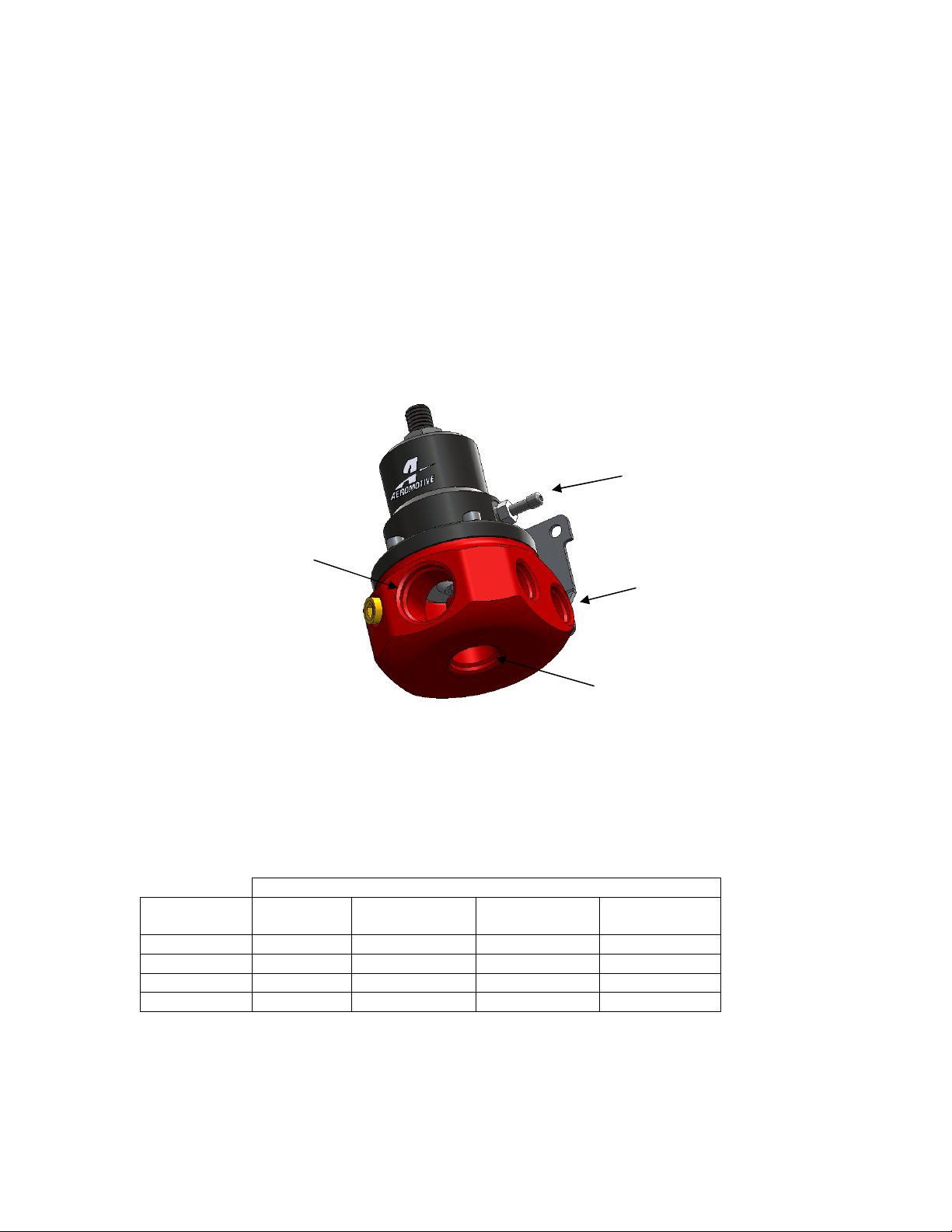
Vac/Boost
Ref Port
AN-10 Inlet Port
AN-06 Outlet Ports
By-pass Port
5. Attach the fuel supply line to the AN-10 inlet port located in the front of the regulator using a cutoff AN-
10 style fitting (Aeromotive P/N 15608 or equivalent) and o-ring.
6. Measure the length of the required bypass line, using the chart below determine the minimum
required return line ID based this length. Attach the fuel return line to the AN-08 bypass port located at
the bottom of the regulator using the appropriately sized fitting, Aeromotive p/n 15605 for a AN-06 line,
p/n 15607 for a AN-08 line, p/n 15641 for a AN-10 line.
Minimum Return Fuel Line ID Chart
Fuel Pump Free Flow Rating (GPH)
Return Line
Length (ft.)
0-5 feet
5-10 feet
10-15 feet
15-20 feet
Note: An undersized return line will prevent the fuel pressure regulator from functioning properly.
1 to 60
GPH
3/8” 3/8” 1/2” 1/2”
3/8” 1/2” 1/2” 5/8”
3/8” 1/2” 5/8” 3/4”
1/2” 1/2” 5/8 3/4”
60 to 120
GPH
120 to 180
GPH
180 to 250
GPH
 Loading...