

Aeromotive 13217 User Manual
13217 INSTALLATION INSTRUCTIONS
CAUTION:
Installation of this product requires detailed knowledge of automotive systems and
repair procedures. We recommend that this installation be carried out by a qualified automotive
technician.
Installation of this product requires handling of gasoline. Ensure you are working in a
well ventilated area with an approved fire extinguisher nearby. Extinguish all open flames,
prohibit smoking and eliminate all sources of ignition in the area of the vehicle before
proceeding with the installation.
When installing this product, wear eye goggles and other safety apparel as needed to
protect yourself from debris and sprayed gasoline.
WARNING!
The fuel system may be under pressure. Do not open the fuel system until any pressure
has been relieved. Refer to the appropriate vehicle service manual for the procedure and
precautions for relieving the fuel system pressure.
The enclosed Aeromotive regulator utilizes two o-ring sealed AN-10 style inlet ports and two oring sealed AN-6 style outlet ports; these regulator ports are NOT PIPE THREAD
THREAD SEALANT.
Performance Specifications: Model 13217
Outlet Fuel Pressure, adjustable 5-12 psi
Inlet Ports 2x AN-10 or O-Ring Sealed Flange
Outlet Ports 2x AN-06
Aeromotive system components are not legal for sale or use on emission controlled motor vehicles.
The following steps are typical of most installations:
1. Once the engine has been allowed to cool, disconnect the negative battery cable and relieve the
fuel system pressure.
2. Place shop towels around the existing regulator to catch any gasoline that is spilled during this step
of the installation. Remove any regulator mounting hardware and connecting fuel lines, then
carefully remove the regulator.
and utilize NO
3. Find a suitable place in the vehicle’s engine compartment to mount the Aeromotive regulator. Using
two flange mounting holes as a template, fabricate a bracket mounting.
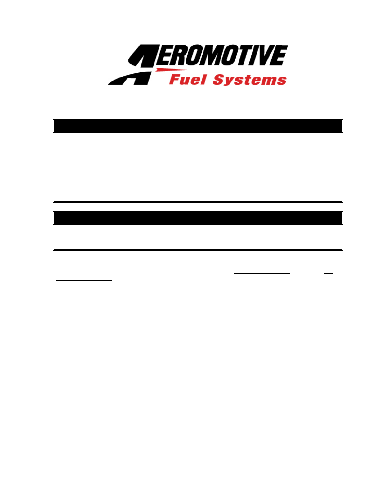
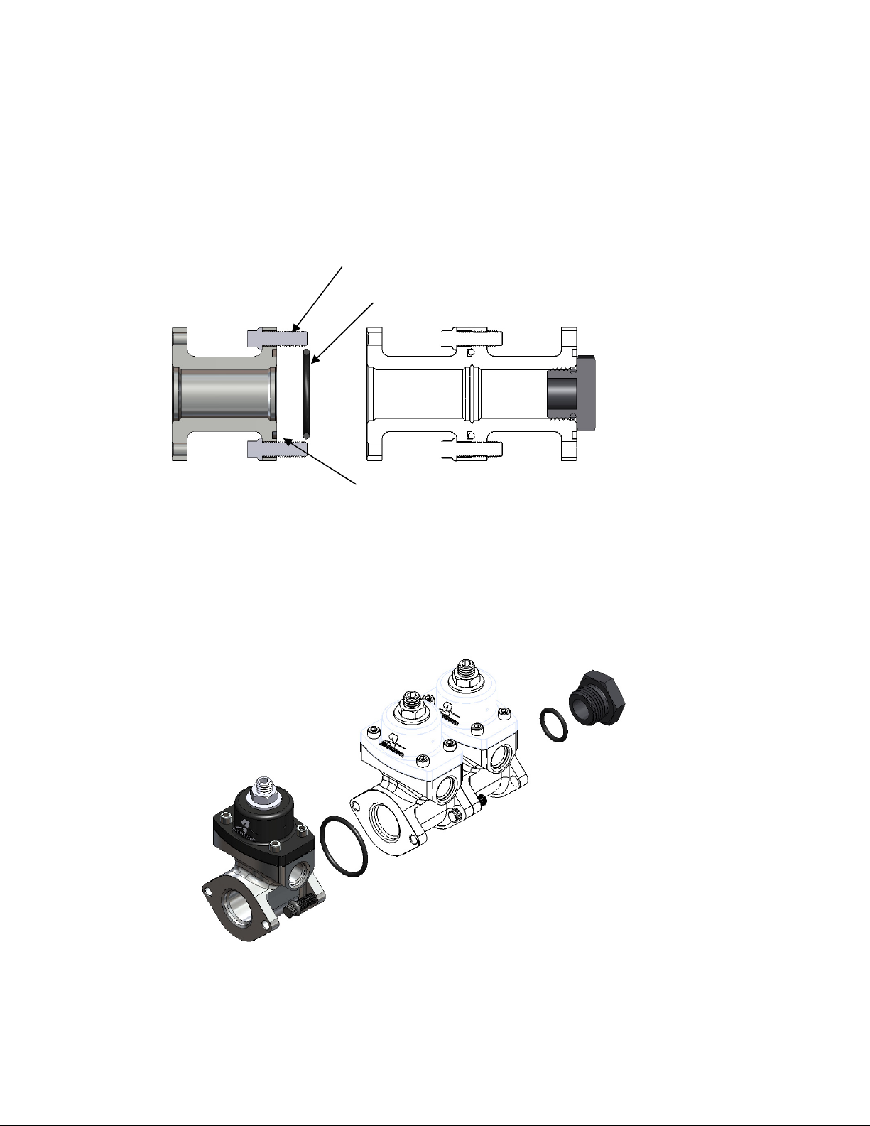
4. If using more than one regulator, place the supplied o-ring in the o-ring groove on one of the
regulator bodies. Using the two supplied mounting screws connect the regulators together. Insure
that the o-ring does not slip out of the o-ring groove and get pinched during assembly.
Mounting Screws
Sealing O-Ring
O-Ring Groove
5. Attach the fuel supply line to the regulators AN-10 inlet port (located at the front or rear of the
regulator) using AN style fittings and o-rings.
AN-12 / AN-10 fitting, Aeromotive P/N 15642
AN-10 / AN-10 fitting, Aeromotive P/N 15608
AN-08 / AN-10 fitting, Aeromotive P/N 15610
AN-06 / AN-10 fitting, Aeromotive P/N 15609
Static / Dead Head Configuration
 Loading...