

Aeromotive 11259 User Manual
AEROMOTIVE
Part # 11209
INSTALLATION INSTRUCTIONS
CAUTION:
Installation of this product requires detailed knowledge of automotive systems and repair
procedures. We recommend that this installation be carried out by a qualified automotive
technician.
Installation of this product requires handling of gasoline. Ensure you are working in a well
ventilated area with an approved fire extinguisher nearby. Extinguish all open flames, prohibit
smoking and eliminate all sources of ignition in the area of the vehicle before proceeding with the
installation.
When installing this product, wear eye goggles and other safety apparel as needed to
protect yourself from debris and sprayed gasoline.
WARNING!
The fuel system may be under pressure. Do not open the fuel system until any pressure
has been relieved. Refer to the appropriate vehicle service manual for the procedure and
precautions for relieving the fuel system pressure.
The enclosed Aeromotive fuel pump utilizes 3/8 NPT style inlet and outlet ports; these ports require pipe
thread sealent.
To use this pump in your vehicle’s fuel system, we strongly recommend the following
Utilize AN-6 size high pressure fuel lines, fittings and o-rings for all connections (Call
Aeromotive for availability.)
Mount the pump lower than and as close as possible to the fuel tank.
A high capacity, 100 micron fuel filter should be installed between the fuel tank or cell and the
pump inlet.
A high capacity 10 micron fuel filter should be installed between the pump outlet and fuel
pressure regulator
We recommend Aeromotive replaceable element filters. Call us for info.
Failure to follow the above recommendations may result in fuel leakage, bursting of the fuel lines, poor
vehicle performance and/or decreased fuel pump life! Improper installation will void all warranties for this
product!
Aeromotive system components are not legal for sale or use on emission controlled motor vehicles.
DO NOT RUN THE PUMP DRY! Excessive wear will result if the pump runs dry.
DO NOT DISASSEMBLE THE PUMP! Disassembly will throw the pump out of calibration and void all
warranties on this product.
DO NOT ATTEMPT TO ADJUST THE OUTLET PRESSURE SCREW! The maximum outlet pressure
has been preset at the factory and locked in its current position. Adjusting it will void all warranties on this
product.
:
The following steps are typical of most installations:
1. Once the engine has been allowed to cool, disconnect the negative battery cable and relieve the fuel
system pressure.
2. Disconnect the existing pump fuel lines. Plug the open fuel line ends and remove the existing pump.
3. Find a suitable place on the vehicle chassis to mount the Aeromotive fuel pump. Make sure the
location will accommodate the pump mounting bolts, will position the pump lower than the fuel tank, is
clear of the exhaust, is clear of any moving suspension or drivetrain components and will keep the
pump clear of road obstructions or debris.
4. Making sure to mount the pump in the upright position and using the pump mounting bracket as a
template, mark and drill two mounting holes to accept ¼” bolts. Mount the pump bracket using two ¼”
bolts, nuts and lock washers. Slide the pump into the bracket and tighten the clamping bolt. Do not
over-tighten the clamping bolt. Doing so can permanently damage the pump motor!
Note: Be sure to route all fuel lines clear of any moving suspension or drivetrain components,
and any exhaust components! Protect fuel lines from abrasion and road obstructions or debris.
5. Connect the fuel tank or cell to the high capacity 100 micron filter. Connect the filter outlet to the 3/8
NPT fuel pump inlet(see Flow arrow on pump). These sections of fuel line should be as short as
possible to reduce the tendencies for vapor lock, cavitation, and premature wear of your Aeromotive
fuel pump.
6. Connect the 3/8 NPT fuel pump outlet to the inlet of your 10 micron fuel filter and the fuel filter outlet
to your fuel line. Connect the other end of the fuel line to the carberetor in the vehicle’s engine
compartment.
Note: Be sure to route all electrical wires clear of any moving suspension or drivetrain
components and any exhaust components! Protect wires from abrasion and road obstructions or
debris.
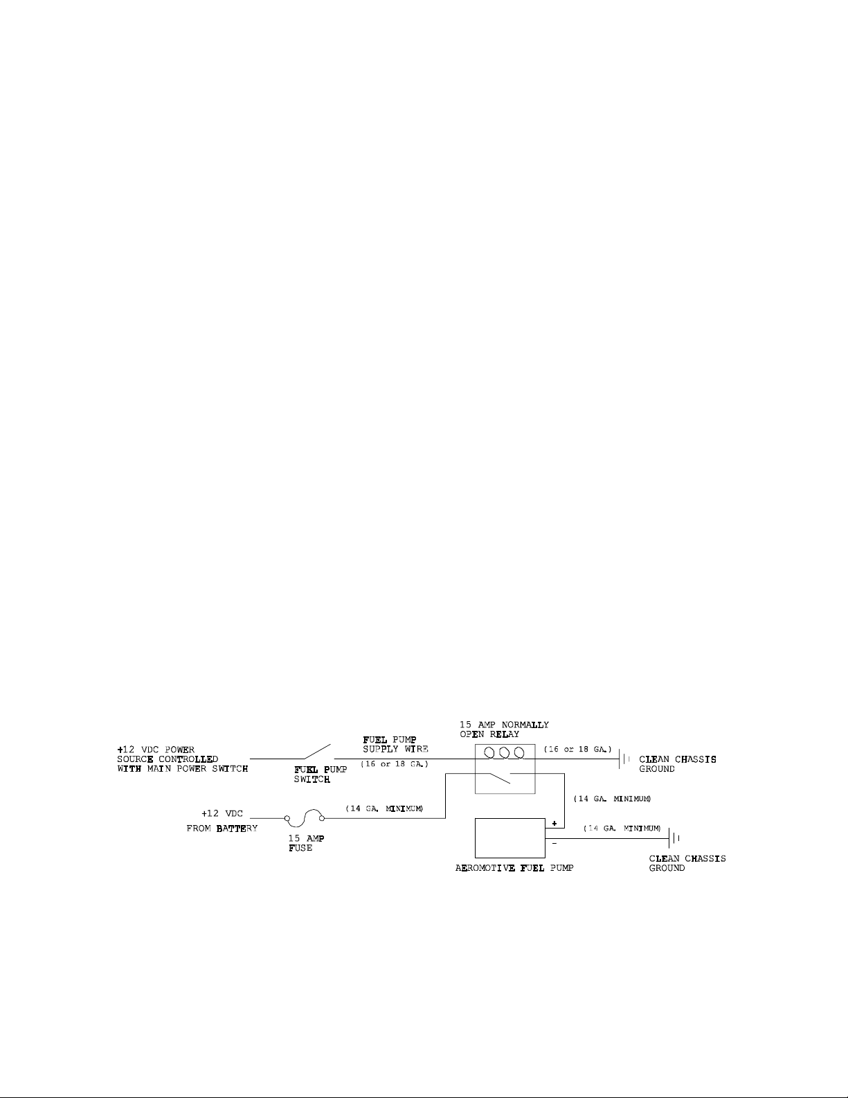
7. Connect electrical power (12 VDC) to the pump. Make sure you use stranded, insulated copper wire,
in the sizes shown, with matching crimp-type connectors for all connections. CAUTION: The pump
must not be connected directly to the battery. Connect the green wire from the fuel pump to a
switched +12 volt source and the black wire to a clean ground as shown in the following diagram:
8. Attach a suitable fuel pressure gauge to the fuel system.
9. Ensure that any spilled fuel and any fuel soaked shop towels are cleaned up and removed from the
vicinity of the vehicle.
 Loading...