

Aeromotive 11105 INSTALLATION INSTRUCTIONS
AEROMOTIVE Part # 11105
INSTALLATION INSTRUCTIONS
Not For Street Use!
CAUTION:
Installation of this product requires detailed knowledge of automotive systems and repair procedures. We
recommend that this installation be carried out by a qualified automotive technician.
Installation of this product requires handling of gasoline. Ensure you are working in a well ventilated area
with an approved fire extinguisher nearby. Extinguish all open flames, prohibit smoking and eliminate all sources
of ignition in the area of the vehicle before proceeding with the installation.
When installing this product, wear eye goggles and other safety apparel as needed to protect yourself
from debris and sprayed gasoline.
WARNING!
The fuel system is under pressure. Do not open the fuel system until the pressure has been relieved.
Refer to the appropriate vehicle service manual for the procedure and precautions for relieving the fuel system
pressure.
The enclosed Aeromotive fuel pump utilizes an o-ring sealed AN-10 style inlet and outlet ports; these ports are NOT PIPE
THREAD and utilize NO THREAD SEALANT.
A high capacity 100 micron fuel filter must be installed between the fuel tank and pump inlet as well as a high capacity 10
micron fuel filter on the pump outlet. We recommend an Aeromotive P/N 12302 on the inlet side and an Aeromotive P/N
12301 on the outlet side. Call us for info.
To use this pump in your vehicle’s fuel system, we strongly recommend the following
Gravity feed the pump by mounting it lower than the fuel cell.
Utilize AN-10 size high pressure fuel lines, fittings and o-rings for all connections from the
fuel cell to the engine.
Failure to follow the above recommendations may result in fuel leakage, bursting of the fuel lines, poor vehicle
performance and/or decreased fuel pump life! Improper installation will void all warranties for this product!
Aeromotive system components are not legal for sale or use on emission controlled motor vehicles.
Performance Specifications: Model 11105
Fuel Compatibility Gasoline & Methyl Alcohol
Port Sizes Inlet & Outlet AN-10
Pump mounting:
Pump should be mounted as low as possible to ease priming.
Due to the large number of applications, no specific mounting instructions are provided.
Pump should turn at half the engine speed.
Recommend a 28-tooth pulley on the pump and a 14-tooth pulley on the crank shaft.
Call for details on Aeromotive mounting kits.
:
The following steps are typical of most installations:
1. Once the engine has been allowed to cool, relieve the fuel system pressure and disconnect the negative battery
cable.
2. Raise the vehicle and support it with jack stands.
3. Find a suitable place on the engine or chassis to mount the Aeromotive fuel pump. Make sure the location will
accommodate the pump mounting bracket, will position the pump as low as possible, is clear of the exhaust, is clear
of any moving suspension or drivetrain components and will keep the pump clear of track obstructions or debris.
Note: Be sure to route all fuel lines clear of any moving suspension or drivetrain components, and any exhaust
components! Protect fuel lines from abrasion and track obstructions or debris.
4. Acquire a 14-tooth, timing belt pulley for the crankshaft, a 28-tooth timing belt pulley for the pump and a ½” wide
timing belt of the desired length. Call Aeromotive for details on mounting kits.
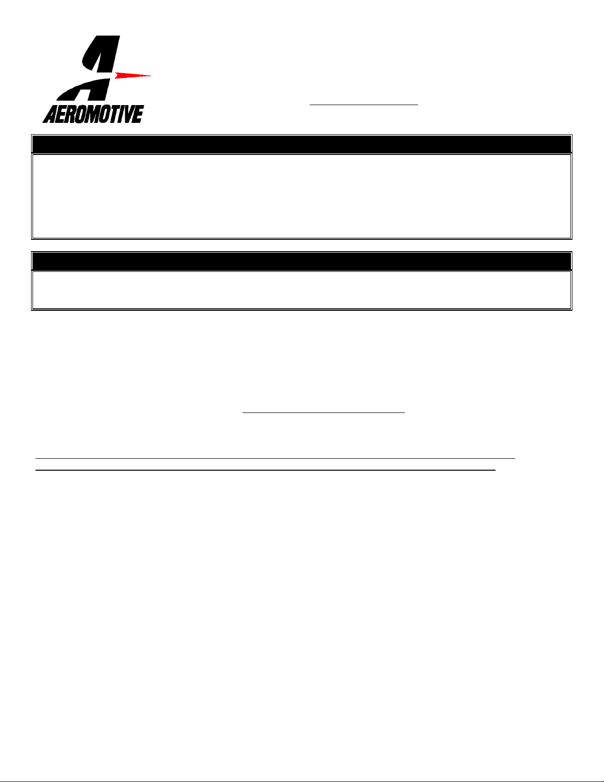
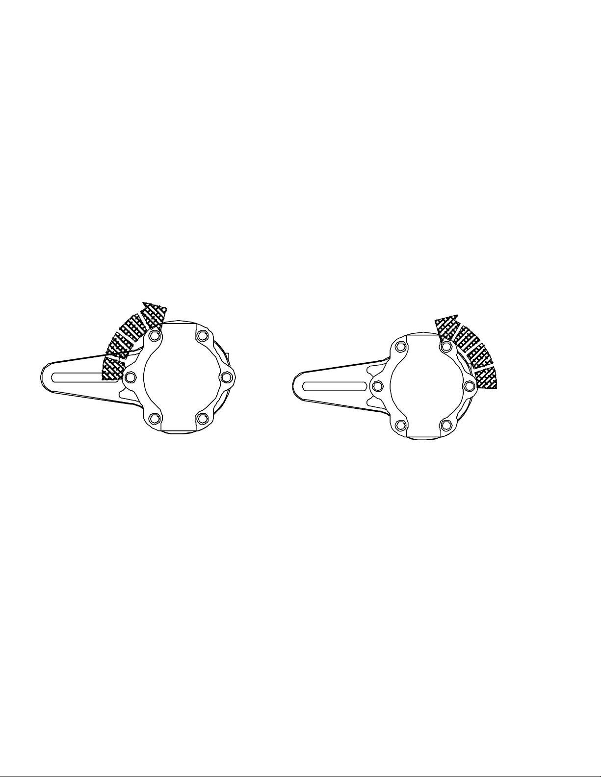
5. Determine which direction the fuel pump shaft will rotate. The direction the shaft is rotated will determine which port is
the inlet and which is the outlet. Using Figure 1a & 1b as a reference identify the fuel pump inlet and outlet ports. If the
fuel pump shaft is rotated in a clockwise direction as viewed from the rear of the pump the inlet and outlet ports will be
as shown in Figure 1a. If the fuel pump shaft is rotated in a counter-clockwise direction the inlet as shown in figure 1a
now becomes the outlet and the outlet in figure 1a is now the inlet, this is shown in figure 1b.
OUTLET
INLET
INLET
Figure 1a Figure 1b
Bracket not included with
Pump. Call Aeromotive
for details on mounting
kits
OUTLET
6. Connect the fuel cell sump to the fuel filter inlet, we recommend using fuel filter Aeromotive p/n 12304 or 12302,
utilizing a minimum of AN-10 steel braided fuel line. Next, connect the fuel filter outlet to the fuel pump inlet utilizing a
minimum of AN-10 steel braided fuel line, refer to Figure 1 for determining the fuel pump inlet.
7. Connect the fuel pump outlet to the vehicle’s fuel system. Make sure you use high pressure (1000 psi minimum)
fuel line for this connection!
Note: Be sure to route all fuel lines clear of any moving suspension or drivetrain components, and any exhaust
components! Protect fuel lines from abrasion and track obstructions or debris.
 Loading...