

Aero Housewares GR900 User Manual
Ground Fault Cable Retractor
GR900 Series
Service Manual
AERO-MOTIVE COMPANY
A Woodhead Industries, Inc. Subsidiary
IMPORTANT SAFETY INSTRUCTIONS
Please read this manual carefully and follow its instructions. Improper use or failure to follow these instructions could
result in serious injury, death or property damage. Operators should be instructed in the safe and proper use and
maintenance of this product. Keep this manual for future reference.
The following safety precautions call attention to potentially dangerous conditions.
DANGER:
WARNING:
CAUTION:
Model GR900 retracts up to 40 feet of #1/0 or #2/0 AWG grounding cable intended to protect equipment and personnel in
the event of a ground fault. The collector rings’ electrical path through the reel has a current carrying capacity greater
then that of the largest cable (#2/0 AWG) to be installed on the reel.
WARNING:
WARNING:
WARNING:
WARNING:
Immediate hazards which WILL result in severe personal injury or death.
Hazards or unsafe practices which COULD result in severe personal injury or death.
Hazards or unsafe practices which MAY result in minor personal injury or product or
property damage.
Failure to lock the cable drum in position with the cable fully extended as instructed, will
create an explosion hazard in the even of fault condition, and may result in property damage,
personal injury, or death.
The internal electrical path is not insulated from the reel frame, therefore, this reel is
unsuitable for other uses other than retracting ground cables. Use for other applications will
create an electrical shock hazard, and could result in property damage, personal injury, or
death.
Failure to install, operate, and maintain the retractor in accordance with these instructions
may result in electrical shock causing property damage, personal injury, or death.
If ground fault has occurred, return the reel to Aero-Motive Company for inspection , and
possible repair before placing back in service. Failure to do so could result in electrical
shock hazard, and may result in property damage, personal injury, or death.
Installation
CAUTION:
CAUTION:
SM3120-18D Page 1 of 6 ©Aero-Motive Company Jul-01
Misalignment of the reel and cable travel direction will cause the cable to be deflected at a
sharp angle around the cable guide rollers
The reel should be bolted securely to a flat metal surface of sufficient strength and rigidity to
support it under all conditions to which it will be subjected. Mounting holes will
accommodate 7/16” or 3/8” bolts. Nothing smaller then 3/8” or 10mm bolts should be used.
MOUNTING
The fixed base of the reel allows mounting in several different positions including base up, base down, or
wall mounted. Here are general mounting requirements:
• Main-shaft must be horizontal.
• Centerline of the spool assembly must be on line with the cable run.
• When mounted overhead in base up position, add a secondary chain, bracket or other safety device
to prevent reel from falling in case the mounting bolts are removed or loosened from vibration.
INSTALLING CABLE
1. Select the proper cable size (#1/0 or #2/0 AWG) to fit the application. The cable should have fine
stranding for flexibility and a jacket suitable for rough handling.
2. After removing the outer drum half (29) pass the end of the cable through the neoprene cable seal
(30).
3. Adjust the neoprene cable seal (30) to fit the cable diameter by cutting away the smaller rings with a
sharp knife. The remaining hole size should be smaller then the cable diameter and must stretch
when
inserting the cable.
4. Finish the end of the cable by either stripping and thinning or applying a suitable pin connector.
5. Insert the cable end or pin connector through the diameter hole provided in the terminal on the rotating
portion of the slip ring assembly (27).
6. Lock the cable securely in place with the set screw and jam nut provided.
7. Clamp the cable to the inside of the inner drum half (33) using the two hole clamp (23), screws (25),
and washers (24). Provide slack between the cable termination on the slip ring assembly (27), and
the
cable clamp (23) to allow free alignment.
8. Reinstall the outer drum half (29) and drum gasket (26) with the four screws.
WARNING:
All steps related to termination of the cable must be followed carefully. Failure to properly
terminate the cable may result in property damage, personal injury, or death.
9. The cable can now be wound onto the cable drum.
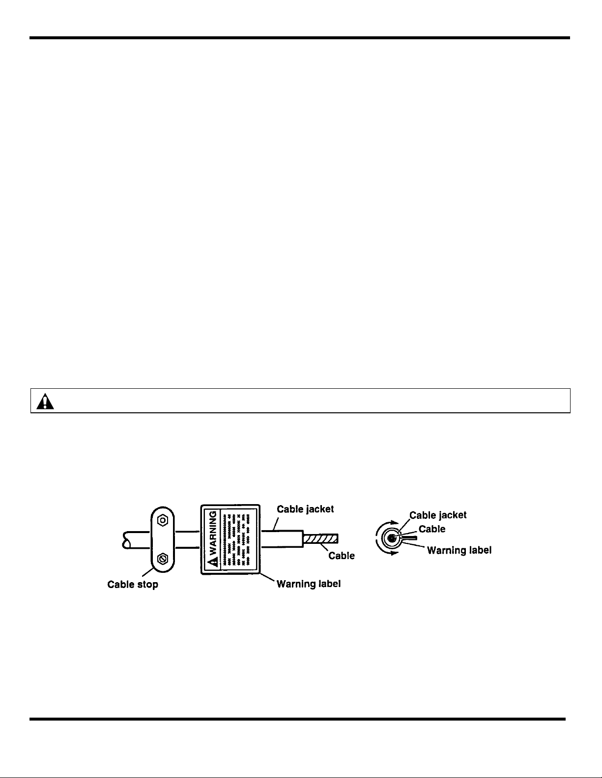
10. A warning label (35) is provided with the retractor and must be attached to the free end of the cable
between the adjustable cable stop (34) and the point where the cable jacket is stripped off (see parts
drawing). To attach the label, remove the adhesive cover from the back and place the center of the
label on the center if the cable. Wrap the cable both ways from the center so both sides (if any re mains) adhere to each other, back to back. (See illustration)
If cable is replaced at a later date contact Aero-Motive Co. 1-800-999-8559 for replacement label.
SM3120-18D Page 2 of 6 © Aero-Motive Company Jul-01
 Loading...