

Page 1

Aerohive Deployment Guide
For HiveAP and HiveManager Devices
Aerohive Technical Publications
Copyright Notice
Copyright © 2009 Aerohive Networks, Inc. All rights reserved.
Aerohive Networks, the Aerohive Networks logo, HiveOS, HiveAP, and HiveManager are trademarks of Aerohive
Networks, Inc. All other trademarks and registered trademarks are the property of their respective companies.
Information in this document is subject to change without notice. No part of this document may be reproduced or
transmitted in any form or by any means, electronic or mechanical, for any purpose, without receiving written
permission from:
Aerohive Networks, Inc.
3150-C Coronado Drive
Santa Clara, CA 95054
P/N 330002-06, Rev. A
1
Page 2

HiveAP Compliance Information
HiveAP Compliance Information
Federal Communication Commission Interference
Statement
This equipment has been tested and found to comply with the limits for
a Class B digital device, pursuant to Part 15 of the FCC Rules. These
limits are designed to provide reasonable protection against harmful
interference in a residential installation. This equipment generates,
uses and can radiate radio frequency energy and, if not installed and
used in accordance with the instructions, may cause harmful
interference to radio communications. Howe ver, there is no guarantee
that interference will not occur in a particular installation. If this
equipment does cause harmful interference to radio or television
reception, which can be determined by turning th e equipment off and
on, the user is encouraged to try to correct the interference by one of
the following measures:
• Reorient or relocate the receiving antenna
• Increase the separation between the equip ment and receiver
• Connect the equipment into an outlet on a circuit diffe rent from
that to which the receiver is connected
• Consult the dealer or an experienced radio/TV technician for help
FCC Caution: Any changes or modifications not expressly approved by
the party responsible for compliance could void the u ser's authority to
operate this equipment. This device complies with Part 15 of the FCC
Rules. Operation is subject to the following two conditions: (1) This
device may not cause harmful interference, and (2) this device must
accept any interference received, including interference that may
cause undesired operation.
In compliance with FCC Part 15 regulations, the HiveAP automatically
discontinues transmission if there is no valid information to transmit or
if there is an operational failure.
Important: FCC Radiation Exposure Statement
This equipment complies with FCC radiatio n exposure limits set forth
for an uncontrolled environment. T his equipment should be installed
and operated with a minimum distance of 20 cen timeters (8 inches)
between the radiator and your body. This transmitter must not be colocated or operating in conjunction with any other antenna or
transmitter.
Wireless 5 GHz Band Statements
To comply with FCC and ETSI regulations when HiveAPs are deployed
outdoors, do not use channels 36, 40, 44, and 48 in the 5.15-5.25 GHz
band.
Because military radar systems use some bands in the 5 GHz spectrum,
WLAN devices operating in these bands must use DFS (Dynamic
Frequency Selection) to detect radar activity and switch channels
automatically to avoid interfering with radar operations. DFS is
required for WLAN devices operating within the 5.25–5.35 GHz UNII-2
and the 5.47–5.725 GHz UNII Mid-Band spectrums in the FCC regions of
North America and the ETSI regions in th e European Com munity. DFS is
not required for WLAN devices operating in the 5.725-5.850 GHz
spectrum in FCC regions. (The 5.725-5.850 GHz spectrum is not
available for wireless use in ETSI regions.) HiveAP 300 series models
support DFS-FCC and DFS-ETSI and are permitted to operate in the
5.25–5.35 GHz and 5.47–5.725 GHz bands in outdoor deployments in the
FCC and ETSI regions.
Note: The term "IC" before the radio certification number s ignifie s that
Industry Canada technical specifications were met.
Industry Canada - Class B
This digital apparatus does not exceed the Class B limits for radio noise
emissions from digital apparatus as set out in the interference-causing
equipment standard entitled "Digital Apparatus," ICES-003 of Industry
Canada.
Cet appareil numérique respecte les limites de bruits radioélectriques
applicables aux appareils numériques de Classe B prescrites dans la
norme sur le matériel brouilleur: "Appareils Numériques," NMB-003
édictée par l'Industrie.
Wi-Fi Certification
The Wi-Fi CERTIFIED™ Logo is a certification mark of the Wi-Fi
®
. The Aerohive HiveAP 20 ag has been certified for WPA™,
Alliance
WPA2™, WMM
following types of EAP (Extensible Authentication Protocol):
•EAP-TLS
•EAP-TTLS/MSCHAPv2
• PEAPv0/EAP-MSCHAPv2
• PEAPv1/EAP-GTC
•EAP-SIM
®
(Wi-Fi Multimedia™), WMM Power Save, and the
EC Conformance Declaration
Marking by the above symbol indicates com pliance with the Essential
Requirements of the R&TTE Directive of the European Union (1999/5/
EC). This equipment meets the following conformance standards:
• EN 60950-1 (IEC 60950-1) - Product Safety
• EN 301 893 - Technical requirements for 5 GHz radio equipment
• EN 300 328 - Technical requirements for 2.4 GHz radio equipment
• EN 301 489-1 / EN 301 489-17 - EMC requirements for radio
equipment
Countries of Operation and Conditions
of Use in the European Community
HiveAPs are intended to be operated in all countries of the European
Community. Requirements for indoor vs. outdoor operation, license
requirements and allowed channels of operation apply in some
countries as described below.
• Before operating a HiveAP, the admin or installer must pro perly
enter the current country of operation in the command line
interface as described in "Appendix A Country Codes" on page 189.
Note to U.S. model owners: To comply with U.S. FCC regulations,
the country selection function has been completely re mo ved f rom
all U.S. models. The above function is for non-U.S. models only.
• HiveAPs automatically limit the allowable channels determined by
the current country of operation. Incorrectly e ntering the countr y
of operation might result in illegal operation and cause harmful
interference to other systems. The admin is obligated to ensure
HiveAPs are operating according to the channel limitations,
indoor/outdoor restrictions and license requirements for each
European Community country as described in this section.
• HiveAPs can be operated indoors or outdoors in all countries of the
European Community using the 2.4 GHz band: Channels 1 - 13,
except where noted below.
– In Italy, you must apply for a license from the national
spectrum authority to operate a HiveAP outdoors.
– In Belgium outdoor operation is only permitted using the 2.46 -
2.4835 GHz band: Channel 13.
– In France outdoor operation is only permitted using the 2.4 -
2.454 GHz band: Channels 1 - 7.
• HiveAPs using the 5.15–5.25 GHz band (Channels 36, 40, 44, 48)
are restricted to indoor use when operated in the European
Community. Because the frequency ranges 5.25–5.35 and 5.47–
5.725 are affected by DFS (Dynamic Frequency Selection), HiveAP
20 and 28 models block channels 52, 56, 60, 64, and 100, 104, 108,
112, 116, 120, 124, 128, 132, 136, 140.
2 Aerohive
Page 3
IVEAP COMPLIANCE INFORMATION
H
The availability of some specific channels and/or operational
frequency bands are country dependent and are firmware
programmed at the factory to match the intended destination.
The firmware setting is not accessible by the end user.
• The 5 GHz Turbo Mode feature is not allowed for operation in any
European Community country. You can find the current setting fo r
this feature in two places. In the HiveManager GUI, click
Configuration > Network Objects> Radio Profiles > profile >
Advanced. In the HiveAP CLI, enter this command: show radio
profile profile. By default, Turbo Mode is disabled.
Declaration of Conformity in Languages
of the European Community
English Hereby, Edgecore, declares that this Radio LAN
Finnish V almistaja Edgecore vakuuttaa täten että Radio LAN
Dutch Hierbij verklaart Edgecore dat het toestel Radio
French Par la présente Edgecore déclare que cet appareil
Swedish Härmed intygar Edgecore att denna Radio LAN
Danish Undertegnede Edgecore erklærer herved, at
German Hiermit erklärt Edgecore, dass sich dieser/diese/
Greek
Italian Con la presente Edgecore dichiara che questo Radio
Spanish Por medio de la presente Manufacturer declara que
Portuguese Manufacturer declara que este Radio LAN device
device is in compliance with the essential
requirements and other relevant provisions of
Directive 1999/5/EC.
device tyyppinen laite on direktiivin 1999/5/EY
oleellisten vaatimusten ja sitä koskevie n direktiivin
muiden ehtojen mukainen.
LAN device in overeenstemming is met de
essentiële eisen en de andere r elevante bep alingen
van richtlijn 1999/5/EG.
Bij deze Edgecore dat deze Radio LAN device
voldoet aan de essentiële eisen en aan de overige
relevante bepalingen van Richtlijn 1999/5/EC.
Radio LAN est conforme aux exigences essentiel les
et aux autres dispositions relatives à la directive
1999/5/CE.
device står I överensstämmelse med de väsentliga
egenskapskrav och övriga relevanta bestämmelser
som framgår av direktiv 1999/5/EG.
følgende udstyr Radio LAN device overholder de
væsentlige krav og øvrige relevante krav i direktiv
1999/5/EF.
dieses Radio LAN device in Übereinstimmung mit
den grundlegenden Anforderungen und den anderen
relevanten Vorschriften der Richtlinie 1999/5/EG
befindet". (BMWi)
Hiermit erklärt Edgecore die Übereinstim mung des
Gerätes Radio LAN device mit den grundlegenden
Anforderungen und den anderen relevanten
Festlegungen der Richtlinie 1999/5/EG. (Wien)
LAN device è conforme ai requisiti essenziali ed alle
altre disposizioni pertinenti stabilite dalla direttiva
1999/5/CE.
el Radio LAN device cumple con los requisitos
esenciales y cualesquiera otras disposiciones
aplicables o exigibles de la Directiva 1999/5/CE.
está conforme com os requisitos essenc iais e outras
disposições da Directiva 1999/5/CE.
HiveAP 20 ag Safety Comp liance
Power Cord Safety
Please read the following safety information carefully befo re installing
a HiveAP.
Warning: Installation and removal of HiveAPs must be carried out by
qualified personnel only.
• HiveAPs must be connected to an earthed (grounded) outlet to
comply with international safety standards.
• Do not connect HiveAPs to an A.C. outlet (power supply) without
an earth (ground) connection.
• The appliance coupler (the connector to the unit and not the wal l
plug) must have a configuration for mating with an EN 60320/IEC
320 appliance inlet.
• The socket outlet must be near the HiveAP and easily accessible.
You can only remove power from a HiveAP by disconnecting the
power cord from the outlet.
• HiveAPs operate under SELV (Safety Extra Low Voltage) conditions
according to IEC 60950. The conditions are only maintained if the
equipment to which they are connected also operates under SELV
conditions.
• A HiveAP receiving power through its PoE (Power over Ethernet)
interface must be in the same building as the equipme nt from
which it receives power.
France and Peru only:
HiveAPs cannot be powered from IT* supplies. If your supplies are of IT
type, then a HiveAP must be powered by 230 V (2P+T) via an isolation
transformer ratio 1:1, with the secondary connection point labelled
Neutral, connected directly to earth (ground).
* Impédance à la terre
Important! Before making connections, make sure you have the correct
cord set. Check it (read the label on the cable) against the descriptio n
on the following page.
Power Cord Set
U.S.A.
and Canada
Denmark The supply plug must comply with Section 107-2-D1,
Switzerland The supply plug must comply with SEV/ASE 1011.
U.K. The supply plug must comply with BS1363 (3-pin 13 A)
Europe The supply plug must comply with CEE7/7
Veuillez lire attentivement les informations de sécurité relatives à
l'installation d'un point d'accès HiveAP.
The cord set must be UL-approved and CSA certified.
Minimum specifications for the flexible cord:
- No. 18 AWG not longer than 2 meters, or 16 AWG
- Type SV or SJ
- 3-conductor
The cord set must have a rated current capacity of at
least 10 A.
The attachment plug must be an earth-grounding
type with NEMA 5-15P (15 A, 125 V) or NEMA 6-15 (15
A, 250 V) configuration.
Standard DK2-1a or DK2-5a.
and be fitted with a 5 A fuse that complies with
BS1362.
The mains cord must be <HAR> or <BASEC> marked and
be of type HO3VVF3GO.75 (minimum).
("SCHUKO").
The mains cord must be <HAR> or <BASEC> marked and
be of type HO3VVF3GO.75 (minimum).
IEC-320 receptacle.
Deployment Guide 3
Page 4

HiveAP Compliance Information
Avertissement: L'installation et la dépose de points d'accès HiveAP
doivent être effectuées uniquement par un personnel qualifié.
• Les points d'accès HiveAP doivent être connectés sur le secteu r
par une prise électrique munie de terre (masse) afin de respec ter
les standards internationaux de sécurité.
• Ne jamais connecter des points d'accès HiveAP à une alimentation
électrique non-pourvue de terre (masse).
• Le boitier d'alimentation (connecté directement au point d'accès)
doit être compatible avec une entrée électrique de type EN
60320/IEC 320.
• La prise secteur doit se trouver à proximité du point d'accès
HiveAP et facilement accessible. Vous ne pouvez mettre hors
tension un point d'accès HiveAP qu'en débranchant son
alimentation électrique au niveau de cette prise.
• Pour des raisons de sécurité, le point d'accès HiveAP fonctionne à
une tension extrêmement b asse, conformément à la norme IEC
60950. Les conditions de sécurité sont valables uniquement si
l'équipement auquel le point d'accès HiveAP est raccordé
fonctionne également selon cette norme.
• Un point d'accès HiveAP alimenté par son interface réseau
Ethernet en mode POE (Power over Ethernet) doit être
physiquement dans le même bâtiment que l'équipement réseau
qui lui fournit l'électricité.
France et Pérou uniquement:
Un point d'accès HiveAP ne peut pas être alimenté par un dispositif à
impédance à la terre. Si vos alimentations sont du type impédance à la
terre, alors le point d'accès HiveAP doit être alimenté par une tension
de 230 V (2P+T) via un transformateur d'isolement à rapport 1:1, avec
le neutre connecté directement à la terre (masse).
Cordon électrique - Il doit être agréé dans le pays d'utilisation
Etats-Unis
et Canada
Danemark La prise mâle d'alimentation doit respecter la section
Suisse La prise mâle d'alimentation doit respecter la norme
Europe La prise secteur doit être conforme aux normes CEE
Le cordon doit avoir reçu l'homologation des UL et un
certificat de la CSA.
Les spécifications minimales pour un cable flexible
- AWG No. 18, ou AWG No. 16 pour un cable de
longueur inférieure à 2 mètres.
- Type SV ou SJ
- 3 conducteurs
Le cordon doit être en mesure d'acheminer un
courant nominal d'au moins 10 A.
La prise femelle de branchement doit être du type à
mise à la terre (mise à la masse) et respecter la
configuration NEMA 5-15P (15 A, 125 V) ou NEMA 615P (15 A, 250 V).
107-2 D1 de la norme DK2 1a ou DK2 5a.
SEV/ASE 1011.
7/7 ("SCHUKO").
LE cordon secteur doit porter la mention <HAR> ou
<BASEC> et doit être de type HO3VVF3GO.75
(minimum).
Warnung: Die Installation und der Ausbau des Geräts darf nur durch
Fachpersonal erfolgen.
• Das Gerät sollte nicht an eine ungeerdete Wechselstromsteckdose
angeschlossen werden.
• Das Gerät muß an eine geerdete Steckdose angeschlossen werden,
welche die internationalen Sicherheitsnormen erfüllt.
• Der Gerätestecker (der Anschluß an das Gerät, nicht der
Wandsteckdosenstecker) muß einen gemäß EN 60320/IEC 320
konfigurierten Geräteeingang haben.
• Die Netzsteckdose muß in der Nähe des Geräts und leicht
zugänglich sein. Die Stromversorgung des Geräts kann nur durch
Herausziehen des Gerätenetzkabels aus der Netzsteckdose
unterbrochen werden.
• Der Betrieb dieses Geräts erfolgt unter den SELV-Bedingungen
(Sicherheitskleinstspannung) gemäß IEC 60950. Diese Bedingungen
sind nur gegeben, wenn auch die an das Gerät angeschlossenen
Geräte unter SELV-Bedingungen betrieben werden.
Stromkabel. Dies muss von dem Land, in dem es benutzt wird
geprüft werden:
U.S.A.
und
Kanada
Danemark Dieser Stromstecker muß die eb ene 107-2-D1, der
Schweiz Dieser Stromstecker muß die SEV/ASE
Europe Europe Das Netzkabel muß vom Typ HO3VVF3GO.75
Der Cord muß das UL gepruft und war das CSA
beglaubigt.
Das Minimum spezifikation fur der Cord sind:
- Nu. 18 AWG - nicht mehr als 2 meter, oder 16 AWG.
- Der typ SV oder SJ
- 3-Leiter
Der Cord muß haben eine strombelastbarkeit aus
wenigstens 10 A.
Dieser Stromstecker muß hat einer erdschluss mit d er
typ NEMA 5-15P (15A, 125V) oder NEMA 6-15P (15A,
250V) konfiguration.
standard DK2-1a oder DK2-5a Bestimmungen
einhalten.
1011Bestimmungen einhalten.
(Mindestanforderung) sein und die Aufschrift <HAR>
oder <BASEC> tragen.
Der Netzstecker muß die Norm CEE 7/7 erfüllen
("SCHUKO").
Bitte unbedingt vor dem Einbauen des HiveAP die folgenden
Sicherheitsanweisungen durchlesen.
Liability Disclaimer
Installation of Aerohive equipment must comply with local and national electrical codes and with other regulations governing this type of installation.
Aerohive Networks, its channel partners, resellers, and distributors assume no liability for personal injury, property damage, or violation of
government regulations that may arise from failing to comply with the instructions in this guide and appropriate electrical codes.
4 Aerohive
Page 5

Chapter 2 The HiveAP 20 ag Platform
The Aerohive HiveAP 20 ag is a new generation wireless access point. HiveAPs have the unique ability to
self-organize and coordinate with each other, creating a distributed-control WLAN solution that offers greater
mobility, security, quality of service, and radio control.
This guide combines product information, installation instructions, and configuration examples for both the HiveAP
and HiveManager platforms. This chapter covers the following topics relating to the HiveAP:
• "HiveAP 20 Product Overview" on page 26
• "Ethernet and Console Ports" on page 28
• "Status LEDs" on page 29
• "Antennas" on page 30
• "Mounting the HiveAP 20" on page 31
• "Device, Power, and Environmental Specifications" on page 33
Deployment Guide 25
Page 6
Chapter 2 The HiveAP 20 ag Platform
Power
Connector
Mounting
Screw
10/100 Mbps
Power-over-
Ethernet Port
Reset
Button
Console
Port
Device
Lock Slot
Fixed Dual-Band Antennas
Connectors for Detachable Single-Band Antennas
Status LEDs
RP-SMA
Connector for
802.11a
Radio Antenna
RP-SMA
Connector for
802.11b/g
Radio Antenna
HIVEAP 20 PRODUCT OVERVIEW
The HiveAP 20 ag is a multi-channel wireless AP (access point). It is compatible with IEEE 802.11b/g (2.4 GHz) and
IEEE 802.11a (5 GHz) standards and supports a variety of Wi-Fi (wireless fidelity) security protocols, including WPA
(Wi-Fi Protected Access) and WPA2.
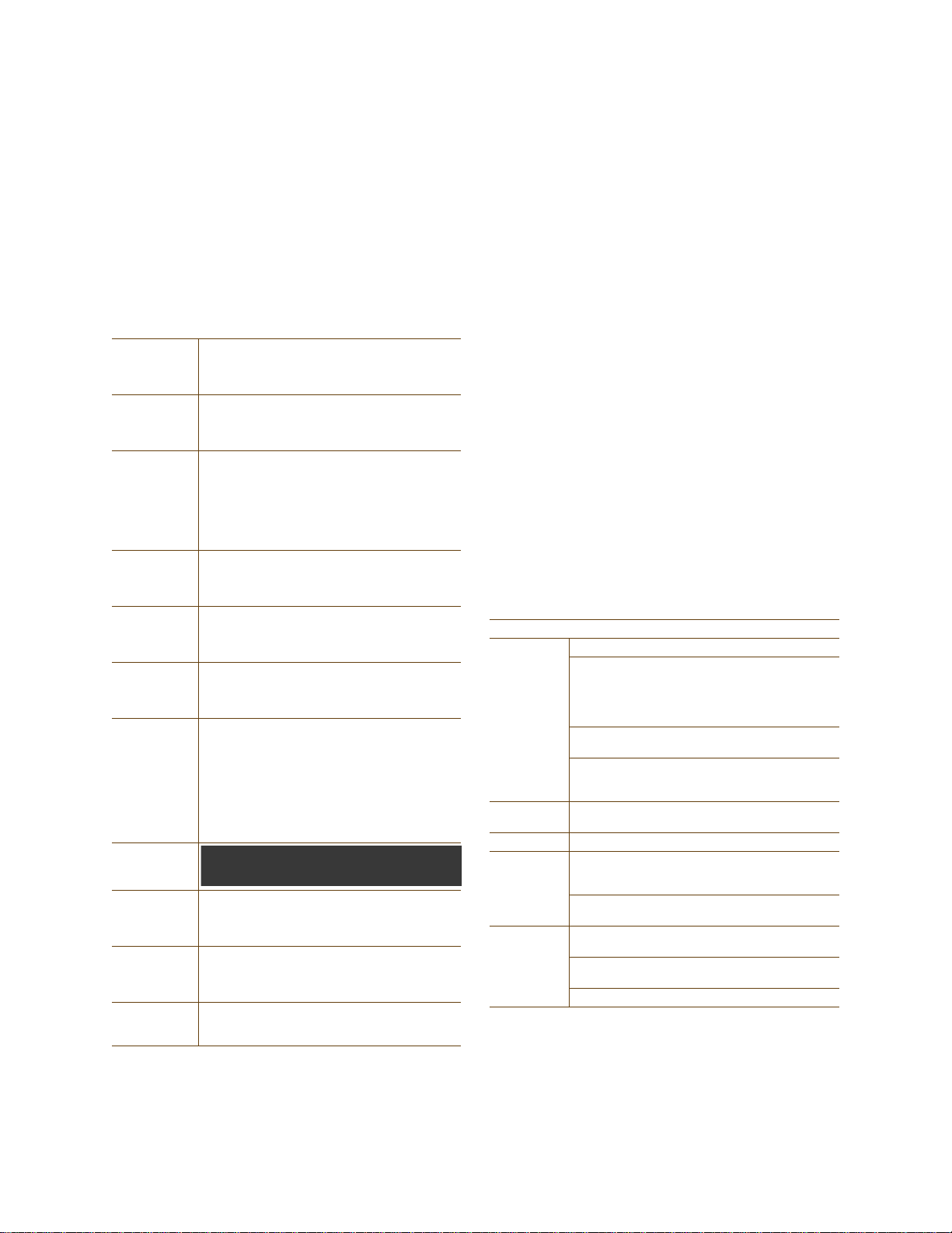
You can see the hardware components on the HiveAP in Figure 1. Each component is described in Table 1.
Figure 1 HiveAP 20 Hardware Components
Table 1 HiveAP 20 Component Descriptions
Component Description
Fixed Dual-Band Antennas The two fixed omnidirectional dipole antennas can operate at two radio
frequencies: 2.4 GHz (for IEEE 802.11b/g) and 5 GHz (for IEEE 802.11a). For
details, see "Antennas" on page 30.
Status LEDs The status LEDs convey operational states for system power, and the LAN,
Access, and Mesh interfaces. For details, see "Status LEDs" on page 29.
802.11a RP-SMA Connector You can connect a detachable single-band antenna, such as the Pulse W1028
dipole antenna for the 5 GHz band, to the male 802.11a RP-SMA (reverse
polarity-subminiature version A) connector. Note that doing so disables the
adjacent fixed antenna.
26 Aerohive
Page 7

HIVEAP 20 PRODUCT OVERVIEW
Component Description
Power Connector The 48-volt DC power connector (0.38 amps) is one of two methods through
which you can power the HiveAP 20. To connect it to a 100 – 240-volt AC
power source, use the AC/DC power adaptor that is available as an extra
option. Because the HiveAP does not have an on/off switch, connecting it to a
power source automatically powers on the device.
Mounting Screw To mount the HiveAP 20 on a surface, attach the mounting plate that ships
with the product to the HiveAP by inserting the two pins on the underside of
the chassis into slots in the plate and tightening the mounting screw. For
details, see "Mounting the HiveAP 20 " on page 31.
10/100 Mbps PoE Port The 10/100-Mbps Ethernet port supports IEEE 802.3af PoE (Power over
Ethernet) and receives RJ-45 connectors. The HiveAP can receive its power
through an Ethernet connection to PSE (power sourcing equipment) that is
802.3af-compatible, such as one of the PoE injectors available as an optional
accessory from Aerohive. (If you connect the HiveAP to a power source
through the power connector and PoE port simultaneously, the device draws
power through the power connector and automatically disables PoE.)
The HiveAP can also connect to the wired network or to a wired device (such
as a security camera) through this port. It is compatible with
10/100Base-T/TX and automatically negotiates half- and full-duplex
connections with the connecting device. It is autosensing and adjusts to
straight-through and cross-over Ethernet cables automatically. It also
automatically adjusts for 802.3af Alternative A and B methods of PoE. For
details, see "Ethernet and Console Ports" on page 28.
Reset Button The reset button allows you to reboot the device or reset the HiveAP to its
factory default settings. Insert a paper clip, or something similar, into the
Reset pinhole and press the reset button. To reboot the device, hold the
button down between 1 and 5 seconds . To return the configuration to the
factory default settings, hold it down for at least 5 seconds. After releasing
the button, the Power LED goes dark, and then glows steady amber while the
firmware loads and the system performs a self-test. After the software
finishes loading, the Power LED glows steady green.
To disable the reset button from resetting the configuration, enter this
command: no reset-button reset-config-enable Pressing the
button between 1 and 5 seconds wi ll still reboot the HiveA P, but pres sing it for
more than 5 seconds will not reset its configuration.
Console Port A male DB-9 serial port to which you can make a console connection using an
RS-232 (or "null modem") cable. The management station from which you
make a serial connection to the HiveAP must have a VT100 emulation
program, such as Tera Term Pro
Hyperterminal
®
(provided with Windows® operating systems). The following
©
(a free terminal emulator) or Hilgraeve
are the serial connection settings: bits per second: 9600, data bits: 8, parity:
none, stop bits: 1, flow control: none.
Device Lock Slot You can physically secure the HiveAP by attaching a lock and cable (such as a
Kensington
®
notebook lock) to the device lock slot. After looping the cable
around a secure object, insert the T-bar component of the lock into the slot
on the HiveAP and turn the key to engage the lock mechanism.
802.11b/g RP-SMA Connector You can connect a detachable single-band antenna, such as the Pulse W1038
dipole antenna for the 2.4 GHz band, to the male 802.11b/g RP-SMA
connector. Note that doing so disables the adjacent fixed antenna.
Deployment Guide 27
Page 8
Chapter 2 The HiveAP 20 ag Platform
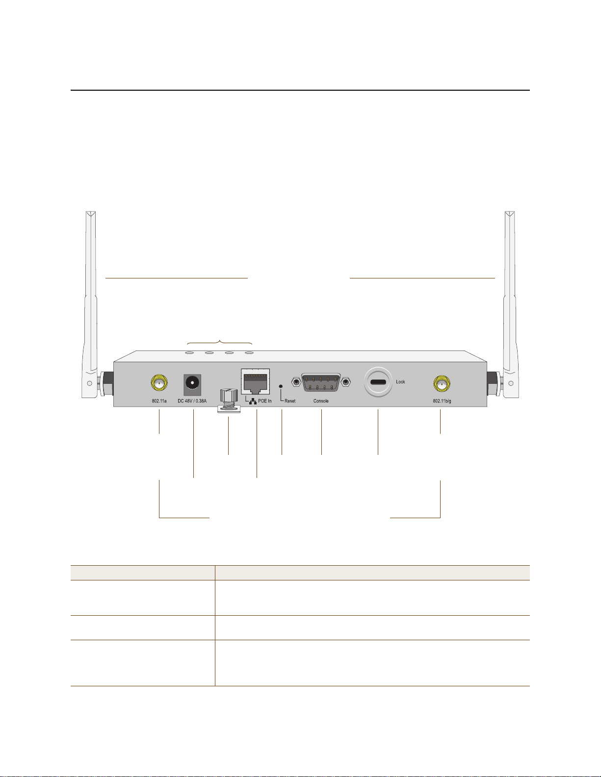
Pin T568A Wire Color
1 White/Green
2 Green
3 White/Orange
4Blue
5 White/Blue
6 Orange
7 White/Brown
8Brown
(View of the PoE port
on the HiveAP)
1 8
Pin Numbers
Pin T568B Wire Color
1 White/Orange
2 Orange
3 White/Green
4Blue
5 White/Blue
6 Green
7 White/Brown
8Brown
T568A-T erminated Ethernet Cable
with an RJ-45 Connector
802.3af Alternative A
(Data and Power on
the Same Wires)
802.3af Alternative B
(Data and Power on
Separate Wires)
Pin Data Signal MDI MDI-X MDI or MDI-X
1 Transmit + DC+ DC– – – –
2 Transmit - DC+ DC– – – –
3 Receive + DC– DC+ – – –
4 (unused) – – – – – – DC+
5 (unused) – – – – – – DC+
6 Receive - DC– DC+ – – –
7 (unused) – – – – – – DC–
8 (unused) – – – – – – DC–
MDI = Medium dependent interface for straight-through connections
MDI-X = Medium dependent interface for cross-over (X) connections
The PoE port is auto-sensing and can automatically adjust to transmit and receive data over straight-through or cross-over Ethernet
connections. Likewise, it can automatically adjust to 802.3af Alternative A and B power delivery methods. Furthermore, when the
Alternative A method is used, the PoE port automatically allows for polarity reversals depending on its role as either MDI or MDI-X.
T568B -terminated Ethernet Cable
with an RJ-45 Connector
T568A and T568B are two standard
wiring termination schemes. Note that
the only difference between them is
that the white/green + solid green pair
of wires and the white/orange + solid
orange pair are reversed.
For straight-through Ethernet
cables—using either the T568A or
T568B standard—the eight wires
terminate at the same pins on each
end.
For cross-over Ethernet cables, the
wires terminate at one end according
to the T568A standard and at the
other according to T568B.
Ethernet and Console Ports
There are two ports on the HiveAP 20: a 10/100Base-T/TX Ethernet port and a male DB-9 console port. Both ports
use standard pin assignments.
The pin assignments in the PoE (Power over Ethernet) Ethernet port follow the TIA/EI A-568-B standard (see
Figure 2). The P oE p ort accepts stan dard types of Ethernet cable—cat3, cat5, cat5e, or cat6—and can receive power
over this cable from power sourcing equipment (PSE) that is 802.3af-compatible. Such equipment can be embedded
in a switch or router , or it can come from purpose-built devices that inject power into the Ethernet line en route to
the HiveAP. Because the PoE port has autosensing capabilities, the wiring termination in the Ethernet cable can be
either straight-through or cross-over.
Figure 2 PoE Wire Usage and Pin Assignments
28 Aerohive
Page 9
HIVEAP 20 PRODUCT OVERVIEW
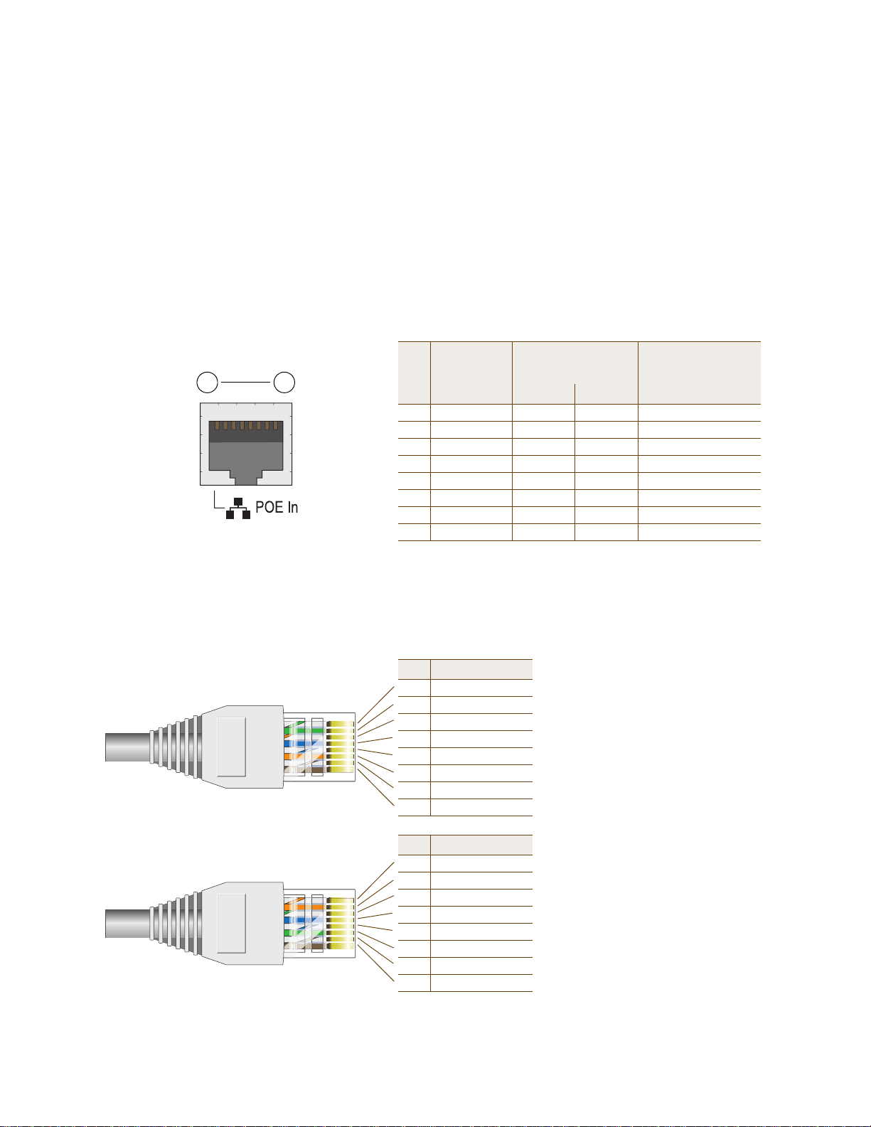
1 2 3 4 5
6 7 8 9
Pin Signal Direction
1 DCD (Data Carrier Detect) (unused)
2 RXD (Received Data) Input
3 TXD (Transmitted Data) Output
4 DTR (Data Terminal Ready) (unused)
5 Ground Ground
6 DSR (Data Set Ready) (unused)
7 RTS (Request to Send) (unused)
8 CTS (Clear to Send) (unused)
9 RI (Ring Indicator) (unused)
Male DB-9 Console Port
(View of the console
port on the HiveAP)
The above pin assignments show a DTE (data terminal equipment)
configuration for a DB-9 connector complying with the RS-232 standard.
Because this is a console port, only pins 2, 3, and 5 need be used.
RS-232 Standard Pin Assignments
The pin assignments in the male DB-9 console port follow the EIA (Electronic Industries Alliance) RS-232 standard. To
make a serial connection between your management system and the console port on the HiveAP, you can use a null
modem serial cable, use another serial cable that complies with the RS-232 standard, or refer to the pin-to-signal
mapping shown in Figure 3 to make your own serial cable. Connect one end of the cable to the console port on the
HiveAP and the other end to the serial (or COM) port on your management system. The management system must
have a VT100 terminal emulation program, such as Tera Term Pro
©
(a free terminal emulator) or Hilgraeve
Hyperterminal® (provided with Windows® operating systems).
Figure 3 Console Port Pin Assignments
Status LEDs
The four status LEDs on the top of the HiveAP 20 indicate various states of activity through their color (dark, green,
amber) and illumination patterns (steady glow or blinking). The meanings of the various color + illumination
patterns for each LED are explained below.
Power
•Dark: No power
• Steady green: Powered on and the firmware is running normally
• Steady amber: Firmware is booting up or is being updated
• Blinking amber: Alarm indicating firmware failure
LAN
• Dark: Ethernet link is down or disabled
• Steady green: Ethernet link is up but inactive
• Blinking green: Ethernet link is up and active
Access
• Dark: Wireless link is disabled
• Steady green: Wireless link is up but inactive
• Blinking green: Wireless link is up and active
Mesh
• Dark: Wireless link is disabled
• Steady green: Wireless link is up but inactive
• Blinking green (fast): Wireless link is up and the HiveAP is searching for other hive members
• Blinking green (slowly): Wireless link is up and active
Deployment Guide 29
Page 10
Chapter 2 The HiveAP 20 ag Platform
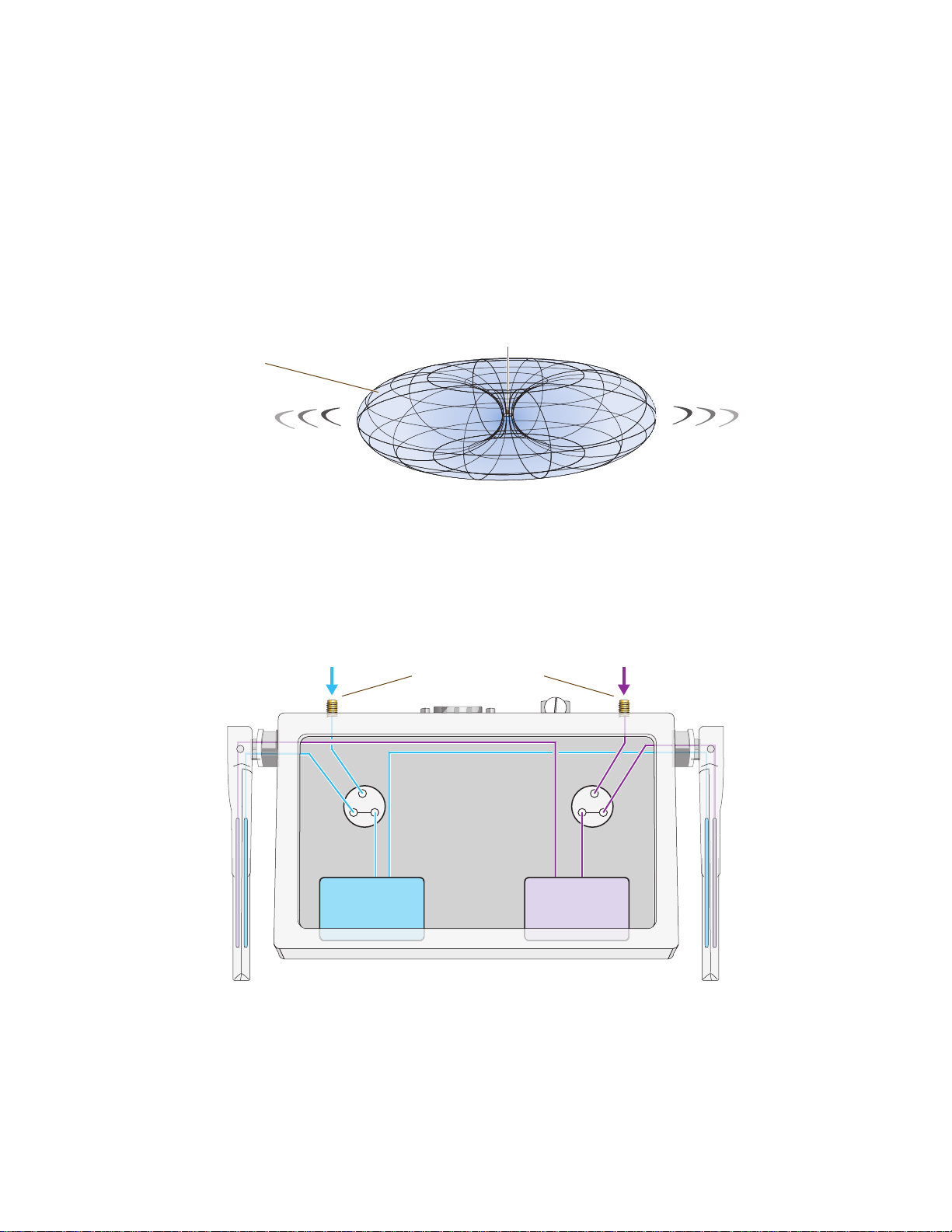
Note: To show the shape of radiation more clearly,
this illustration depicts the coverage provided by
only one active antenna and is not drawn to scale.
The omnidirectional antennas
radiate equally in all directions,
forming a toroidal pattern.
HiveAP
Radio 1
RF 802.11b/g
2.4 GHz
Radio 2
RF 802.11a
5 GHz
Antenna
Switch 1
Antenna
Switch 2
RP-SMA Connectors
802.11a/b/g
Dual-Band
Fixed
Antenna
802.11a/b/g
Dual-Band
Fixed
Antenna
Cut-away view of the HiveAP to show the relationship
of the antennas and the two internal radios.
Antennas
The HiveAP 20 includes two fixed dual-band antennas with 3-dBi gains. These antennas are omnidirectional,
providing fairly equal coverage in all directions in a toroidal (donut-shaped) pattern around each anten na. When the
antennas are vertically positioned, coverage expands primarily on the horizontal plane, extending horizontally much
more than vertically. See Figure 4, which shows the toroidal pattern emanating from a single vertically positioned
antenna. To change coverage to be more vertical than horizontal, position the antennas horizontally. You can also
resize the area of coverage by increasing or decreasing the signal strength.
Figure 4 Omnidirectional Radiation Pattern
The pair of fixed dual-band antennas operate concurrently in two different frequency ranges: 2.4 GHz (IEEE
802.11b/g) and 5 GHz (IEEE 802.11a). Using two different frequency ranges reduces the probability of interference
that can occur when numerous channels operate within the same range. Conceptually, the relationship of antennas
and radios is shown in Figure 5.
Figure 5 Antennas and Radios
If you connect an external antenna to an RP-SMA connector, you must enter the following command to move the
appropriate interface from the adjacent fixed antenna to the external antenna:
interface interface radio antenna external
30 Aerohive
Page 11
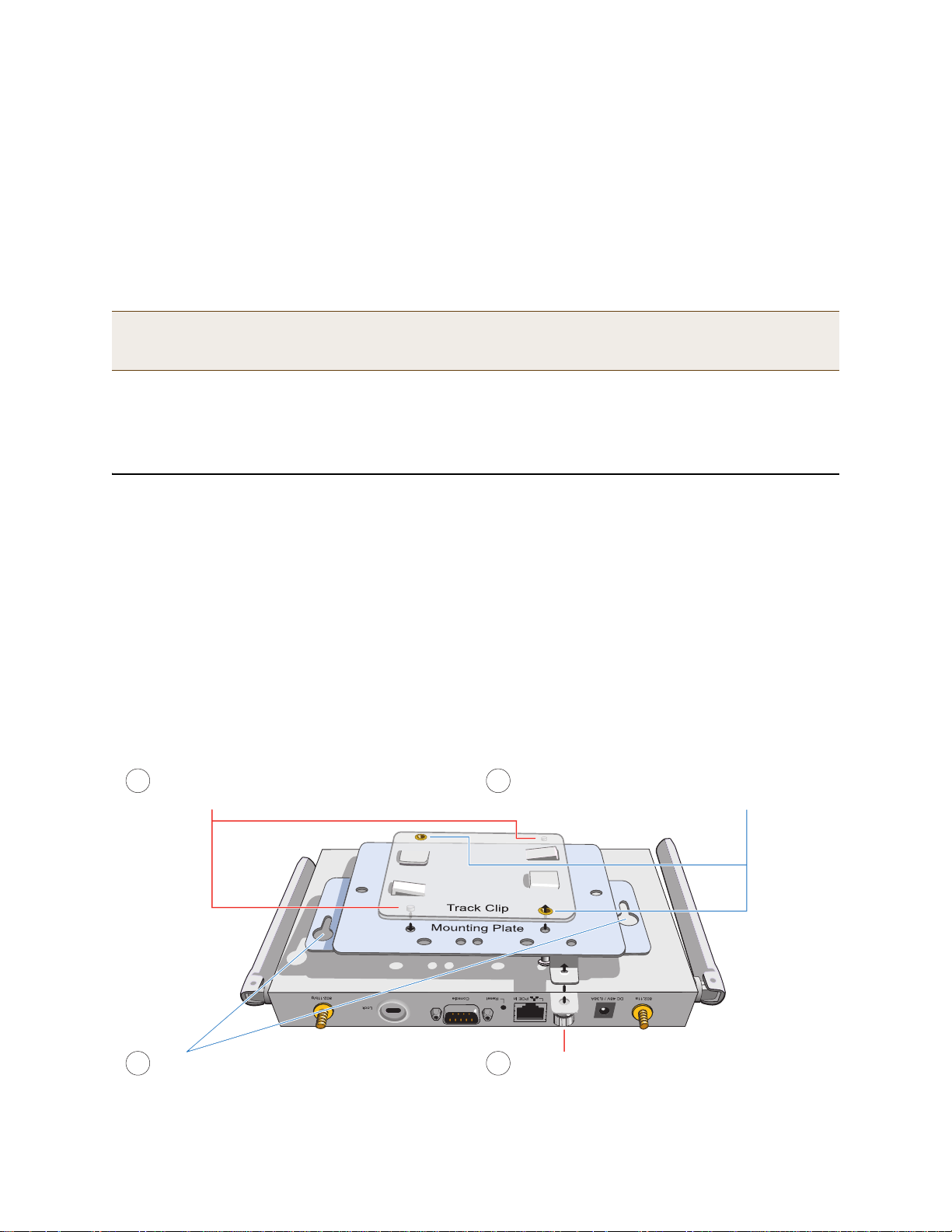
MOUNTING THE HIVEAP 20
Align the two projecting posts on the underside of
the track clip with holes in the mounting plate.
Using the two cross-head screws that ship with the
track clip, fasten the mounting plate to the track clip.
Insert the pins on the underside of the HiveAP
into the two slots in the mounting plate.
Use the mounting screw to secure the HiveAP
to the plate.
1
2
3
4
The wifi0 interface links to radio 1 (frequency range = 2.4 GHz for IEEE 802.11b/g), and the wifi1 interface links to
radio 2 (frequency range = 5 GHz for IEEE 802.11a). These interface-to-radio relationships are permanent. However,
the interface-to-antenna relationships can be shifted. In other words, you can change which antenna—fixed or
external—the wifi0 and wifi1 interfaces use. For example, to link the wifi0 interface to an external antenna
connected to the 802.11b/g RP-SMA connector (for radio 1), enter the following command:
interface wifi0 radio antenna external
If you do not enter this command, the wi fi0 interface and all its subinterfac es (wifi0.1, wifi0.2, wifi0.3 … wifi0.7)
continue to use both fixed antennas.
Note: After entering the above command, the radio to which you attached the external antenna uses the
external antenna and the fixed antenna on the opposite side of the HiveAP. Attaching an external antenna
only disconnects the adjacent fixed antenna. Note the two antenna switches shown in Figure 5 on page 30.
To unlink the wifi0 interface from the external antenna and return it to the fixed antennas, enter this command:
interface wifi0 radio antenna internal
MOUNTING THE HIVEAP 20
Using the mounting plate and track clip, you can mount the HiveAP 20 to the tracks of a dropped ceiling grid. Using
just the mounting plate, you can mount the HiveAP to any surface that can support its weight (1.5 lb., 0.68 kg).
Ceiling Mount
To mount the HiveAP 20 to a track in a dropped ceiling, you need the mounting plate, track clip, and two cross-head
screws that ship with the track clip. You also need a cross-head screw driver and—most likely—a ladder.
Attach the track clip to the mounting plate, and then attach the clip-plate combina tion to the Hive AP 20, as shown
in Figure 6.
Figure 6 Attaching the HiveAP 20 to the Mounting Plate and Track Clip
Deployment Guide 31
Page 12
Chapter 2 The HiveAP 20 ag Platform
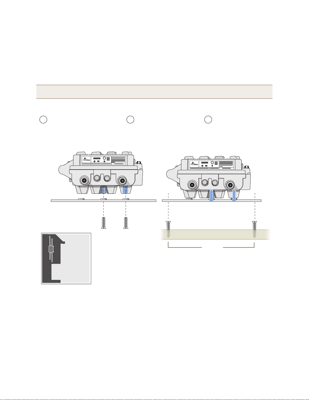
Use the mounting screw
to secure the HiveAP 20
to the plate.
Insert the pins on the underside of
the HiveAP 20 into the two slots.
With the two wings at the sides of the plate extending
away from the surface, attach the mounting plate to a
secure object such as a wall, ceiling, post, or beam.
1
2
3
Note: There are a variety of holes through which you can
screw or nail the plate in place. Choose the two or three
that best suit the object to which you are attaching it.
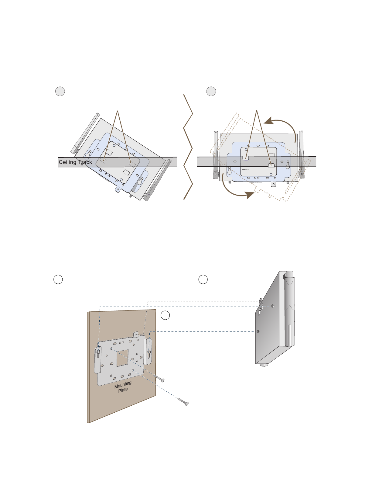
Nudge the ceiling tiles slightly away from the track to clear some space. Then attach the track clip to the ceiling
track as shown in Figure 7. When done, adjust the ceiling tiles back into their former position.
Figure 7 Attaching the HiveAP to a Dropped Ceiling Track
5
Press the track clip against the ceiling track so
that the the track contacts the two pressure tabs
and pushes them flush with the track clip.
(bird’s eye view
with ceiling tiles
removed for clarity)
6
Rotate the HiveAP and the mounting
accessories attached to it until the two
clipping tabs grip the ceiling track.
Surface Mount
You can use the mounting plate to attach the HiveAP 20 to any surface that supports its weight, and to which you
can screw or nail the plate. First, mount the plate to the surface, and then attach the device to the plate, as shown
in Figure 8.
Figure 8 Mounting the HiveAP on a Wall
32 Aerohive
Page 13

DEVICE, POWER, AND ENVIRONMENTAL SPECIFICATIONS
DEVICE, POWER, AND ENVIRONMENTAL SPECIFICATIONS
Understanding the range of specifications for the HiveAP 20 is necessary for optimal deployment and device
operation. The following specifications describe the physical features and hardware components, the p ower adapter
and PoE (Power over Ethernet) electrical requirements, and the temperature and humidity ranges in which the
device can operate.
Device Specifications
• Chassis dimensions: 8 1/4" W x 1" H x 4 15/16" D (21 cm W x 2.5 cm H x 12.5 cm D)
• Weight: 1.5 lb. (0.68 kg)
• Antennas: Two fixed dual-band 802.11a/b/g antennas, and two RP-SMA connectors for detachable single-band
802.11a or 802.11b/g antennas
• Serial port: DB-9 (bits per second: 9600, data bits: 8, parity: none, stop bits: 1, flow control: none)
• Ethernet port: autosensing 10/100Base-T/TX Mbps, with IEEE 8 02.3af-compliant PoE (Power over Ethernet)
Power Specifications
• AC/DC power adapter:
• Input:100 – 240 VAC
• Output: 48V/0.38A
• PoE nominal input voltages: 48 V, 0.35A
• RJ-45 power input pins: Wires 4, 5, 7, 8 or 1, 2, 3, 6
Environmental Specifications
• Operating temperature: 32 to 122 degrees F (0 to 50 degrees C)
• Storage temperature: -4 to 158 degrees F (-20 to 70 degrees C)
• Relative Humidity: Maximum 95%
Deployment Guide 33
Page 14

Chapter 2 The HiveAP 20 ag Platform
34 Aerohive
Page 15

Chapter 3 The HiveAP 28 Outdoor Platform
The Aerohive HiveAP 28 is a new generation wireless access point that is customized for outdoor use. It is mountable
in any direction and on any hard surface, post, or wire strand. It can receive power either through a n Ethernet cable
or power cord.
Note: Do not open the HiveAP 28 chassis. There are no serviceable parts inside.
This guide combines product information, installation instructions, and configuration examples for both the HiveAP
and HiveManager platforms. This chapter covers the following topics relating to the HiveAP 28:
• "HiveAP 28 Product Overview" on page 36
• "Ethernet Port" on page 37
• "Power Connector" on page 38
• "Antennas" on page 39
• "Mounting the HiveAP 28 and Attaching Antennas" on page 40
• "Pole Mount" on page 41
• "Strand Mount" on page 42
• "Surface Mount" on page 43
• "Attaching Antennas" on page 44
• "Device, Power, and Environmental Specifications" on page 46
Deployment Guide 35
Page 16
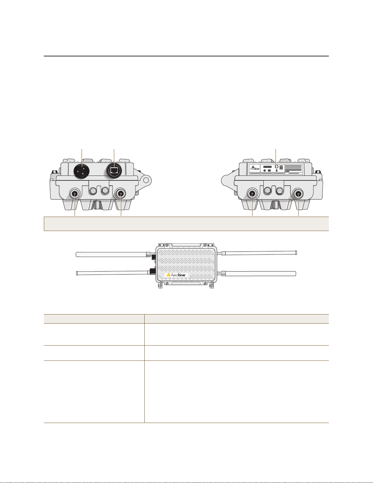
Chapter 3 The HiveAP 28 Outdoor Platform
Power
Connector
10/100 Mbps
Power-over-
Ethernet Port
Type N female connectors for
detachable single-band antennas
For the 802.11a
Radio Antenna
For the 802.11b/g
Radio Antenna
For the 802.11a
Radio Antenna
For the 802.11b/g
Radio Antenna
FCC Compliance Label
(Plus model, serial number, MAC
address, and FCC ID number)
802.11a Main Antenna (5 GHz) 802.11b/g Main Antenna (2.4 GHz)
802.11b/g Auxiliary Antenna (2.4 GHz) 802.11a Auxiliary Antenna (5 GHz)
HIVEAP 28 PRODUCT OVERVIEW
The HiveAP 28 is a multi-channel wireless AP (access point) for outdoor use. It is compatible with IEEE 802.11b/g
(2.4 GHz) and IEEE 802.11a (5 GHz) standards and supports a variety of Wi-Fi (wireless fidelity) security protocols,
including WP A (Wi-Fi Protected Access) and WPA2.
You can see the hardware components on the HiveAP 28 in Figure 1. Each component is described in Table 1.
Figure 1 HiveAP 28 Hardware Components
5 GHz 2.4 GHz 5 GHz 2.4 GHz
Table 1 HiveAP 28 Component Descriptions
Component Description
Detachable Single-Band Antennas The two pairs of detachable omnidirectional dipole antennas operate at
two radio frequencies: one pair at 2.4 GHz (for IEEE 802.11b/g) and the
other at 5 GHz (for IEEE 802.11a). For details, see "Antennas" on page 39.
Type N Connectors (Female) Attach antennas to the HiveAP 28 through these connectors. For details,
see "Attaching Antennas" on page 44.
Waterproof Power Connector Using the power connector is one of two methods through which you can
power the HiveAP 28. To connect it to a 100 – 240-volt AC power source,
use the power cable that ships with the product as an extra option.
Because the HiveAP does not have an on/off switch, connecting it to a
power source automatically powers on the device. The power source
must have a readily accessible service disconnect switch incorporate d
into the fixed wiring installation so that you have the ability to turn the
power on and off. (The other method that the HiveAP can obtain power is
through its PoE port.)
36 Aerohive
Page 17
HIVEAP 28 PRODUCT OVERVIEW
2
Compression Nut
End Cap
Gasket
(inside)
Gasket
(squeezed out)
1
3
Slide the Ethernet cable through the two
halves of the waterproof RJ-45 connector
assembly, screw the halves loosely together,
and then plug the cable into the Ethernet port.
Tighten the compression nut
into the Ethernet port housing
on the chassis.
Tighten the end cap until
the gasket is squeezed out
the opening and forms a
watertight seal around the
cable.
Component Description
10/100 Mbps PoE Port The 10/100-Mbps Ethernet port supports IEEE 802.3af PoE (Power over
Ethernet) and receives RJ-45 connectors. The HiveAP can receive its
power through an Ethernet connection to PSE (power sourcing
equipment) that is 802.3af-compatible, such as one of the PoE injectors
available as an optional accessory from Aerohive. (If you connect the
HiveAP to a power source through the power connector and PoE port
simultaneously, the device draws power through the power connector and
automatically disables PoE.)
The HiveAP 28 can also connect to the wired network or to a wired devi ce
(such as a security camera) through this port. It is compatible with
10/100Base-T/TX and automatically negotiates half- and full-duplex
connections with the connecting device. It is autosensing and adjusts to
straight-through and cross-over Ethernet cables auto mati cally
(MDI/MDI-X). It also automatically adjusts for 802.3af Alternative A and B
methods of PoE. For detai ls, see "Ethernet Port".
Ethernet Port
The HiveAP 28 has a 10/100Base-T/TX PoE (P ower over Et hern et) p ort. Its pi n a ssignme nt s follow the TI A/EI A-5 68 -B
standard (see Figure 2 on page 28). The PoE port accepts standard types of Ethernet cable—cat3, cat5, cat5e, or
cat6—and can receive power over this cable from power sourcing equipment (PSE) that is 802.3af-compatible. Such
equipment can be embedded in a switch or router , or it can come from purpose-built devices that inject power into
the Ethernet line en route to the HiveAP. Because the PoE port has autosensing capabilities, the wiring termination
in the Ethernet cable can be either straight-through or cross-over (MDI/MDI-X). For outdoor deployments use
weatherproofed shielded twisted pair (STP) Ethernet cables.
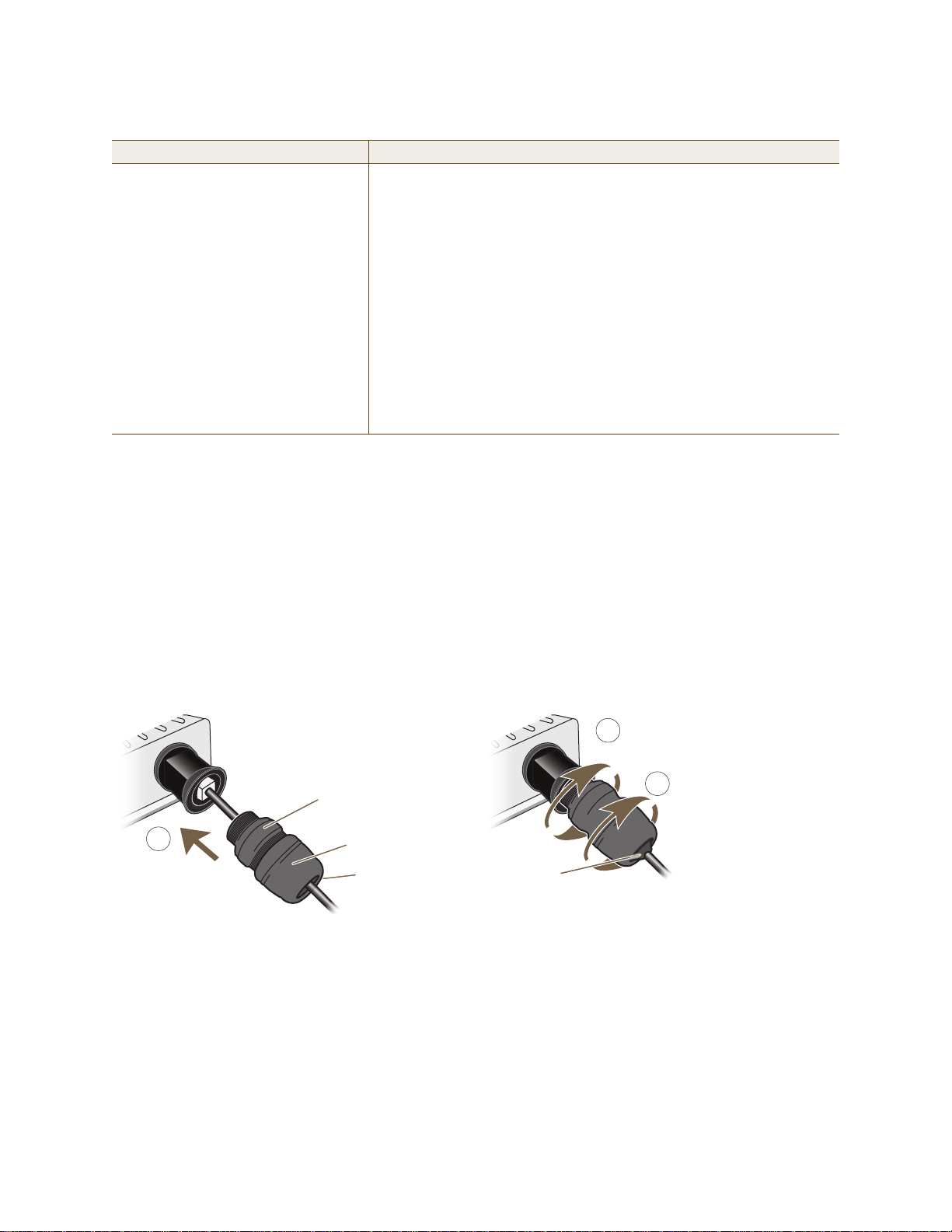
To ensure a waterproof seal for the Ethernet connection, use the RJ-45 connector assembly, which comes in three
parts: a compression nut, end cap, and gasket.
Figure 2 Connecting the Ethernet Cable
1. Insert one end of the Ethernet cable through the waterproof RJ-45 connector assembly and plug the cable into
the Ethernet port.
2. Tighten the compression nut by twisting it clockwise into the Ethernet port housing on the chassis.
3. Tighten the end cap by twisting it clockwise onto the compression nut and tighten until the rubber gasket
emerges and wraps itself around the Ethernet cable.
The Ethernet connection is now sealed and waterproof.
Deployment Guide 37
Page 18

Chapter 3 The HiveAP 28 Outdoor Platform
4. Connect the other end of the Ethernet cable to PSE (power sourcing equipment) such as a pow er inje ctor if the
HiveAP 28 receives power through PoE, or directly to a network device such as a switch if it receives power
through a power cord.
Note: To prevent damage to the HiveAP 28 or power injector when using PoE to provide power, connect the
Ethernet cable from the power injector to the HiveAP 28, and connect the injector to a power jack
before applying power.
If the Ethernet cable connects the HiveAP to another device that is indoors, you must install appropriate
lightning protection at the point before it enters the building. Failing to do so might cause damage t o the
equipment as well as serious injury or death.
Note: When the HiveAP acts as a mesh point and does not use the Ethernet port, cover the Ethernet port with a
connector cap to prevent water intrusion and possible safety hazards.
Power Connector
The HiveAP 28 can receive power through an Ethernet cable using PoE or through a power cord. Aerohive
recommends using either PoE or wiring the power cord directly to a 100 – 240-volt AC power source. Only plug the
power cord into an electric outlet when configuring the device before deployment or whe n testing it in the lab.
Note: When the HiveAP receives power through PoE, cover the power connector with a connector cap to prevent
water intrusion and possible safety hazards.
To connect the power cord to the HiveAP 28:
1. Align the slot in the power cord plug with the small tab at the top of the three-pin power connector, and slide
the plug firmly over the pins until it is fully seated in the power connector.
2. Slide the cover over the connector and tighten it by turning the cover clockwise.
3. Install a lightning protector between the HiveAP 28 and its power source.
4. When possible, run the cord through a conduit to protect it from the elements. Where the cord is exposed,
allow enough slack in it to create a drip loop. Leaving some slack in the cord lets water run away from the
connections at each end. Use only a weatherproof power cord, such as the cord that ships with the HiveAP 28.
5. Strip the other end of the power cord and wire it directly to a power source, such as a junction box that has a
service disconnect switch that you can use to turn the power on and off. Also, because the HiveAP 28 does not
have short-circuit (over current) protection built into it, it relies on the protection provided by the power
source to which you connect it. Ensure that the protective device, such as a circuit breaker, is not rated greater
than 15A. Furthermore, if you need to install the HiveAP 28 in a wet or damp location, the AC branch circuit
that is powering it must be provided with ground fault protection (GFCI), as required by Article 210 of the
National Electrical Code (NEC).
Note: The HiveAP 28 must be grounded. Do not operate it unless there is a suitably installed ground
conductor. Contact the appropriate electrical inspection authority or an electrician if you are
uncertain that suitable grounding is available.
38 Aerohive
Page 19
HIVEAP 28 PRODUCT OVERVIEW
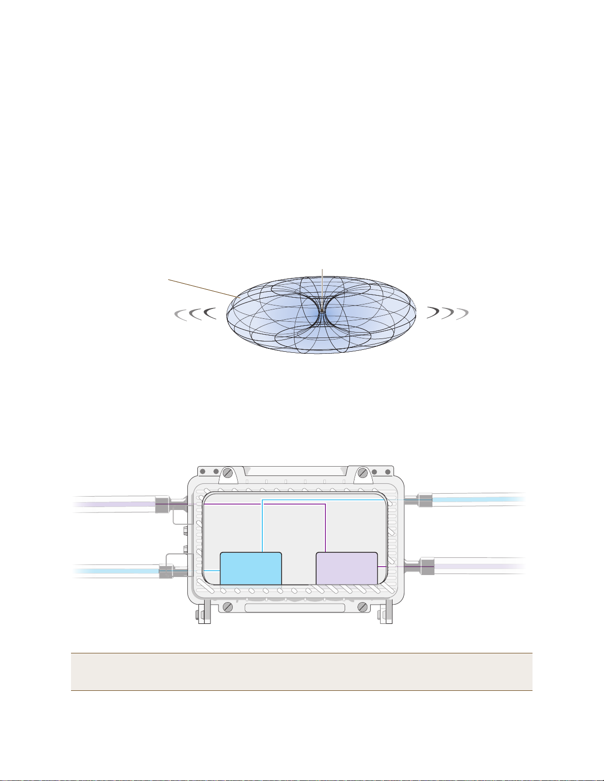
Note: To show the shape of radiation more clearly,
this illustration depicts the coverage provided by
only one active antenna and is not drawn to scale.
The omnidirectional antennas
radiate equally in all directions,
forming a toroidal pattern.
HiveAP
The two 802.11b/g antennas link internally to Radio 1
and broadcast in the 2.4 GHz frequency range.
802.11a Main Antenna
802.11b/g Main Antenna
802.11b/g Auxiliary Antenna
802.11a Auxiliary Antenna
The two 802.11a antennas link internally to Radio 2
and broadcast in the 5 GHz frequency range.
Radio 1
RF 802.11b/g
2.4 GHz
Radio 2
RF 802.11a
5 GHz
Antennas
The HiveAP 28 includes two detachable single-band antennas with 8dBi gains (802.11b/g) and two detachable
single-band antennas with 10dBi gains (802.11a). These antennas are omnidirectional, providing fairly equal
coverage in all directions in a toroidal (donut-shaped) pattern around each antenna. When the antennas are
vertically positioned, coverage expands primarily on the horizontal plane, extending horizontally much more than
vertically. See Figure 3, which shows the toroidal pattern emanating from a single vertically positioned antenna.
Note that when high gain antennas are added, the torus shape becomes somewhat elongated or compressed. If the
HiveAP 28 is mounted higher than 20 feet the center of the torus curves inw ard so that the connection quality,
directly underneath the center of the HiveAP 28, becomes compromised.
To change coverage to be more vertical than horizontal, position the HiveAP so that the antennas are on a
horizontal plane. You can also resize the area of coverage by increasing or decreasing the signal strength.
Figure 3 Omnidirectional Radiation Pattern
The pairs of antennas operate concurrently in two different frequency ranges: 2.4 GHz (IEEE 802.11b/g) and 5 GHz
(IEEE 802.11a). Using two different frequency ranges reduces the probability of interference that can occur when
numerous channels operate within the same range. C onceptually, the relationship of antennas and radios is shown in
Figure 4. (For information about attaching the antennas to the HiveAP 28, see "Attaching Antennas" on page 44.)
Figure 4 Antennas and Radios
Note: The HiveAP 20 uses the interface interface radio antenna external command to enable an
external antenna attached to it. Entering this command on the HiveAP 28 disables the antenna on the
opposite side of the device from the radio to which the interface is linked and results in a loss of diversity.
Deployment Guide 39
Page 20

Chapter 3 The HiveAP 28 Outdoor Platform
MOUNTING THE HIVEAP 28 AND ATTACHING ANTENNAS
Using the mounting accessories (available separately) you can mount the HiveAP in various locations:
• "Pole Mount" on page 41 – Mount the HiveAP 28 on a pole such as a street light.
• "Strand Mount" on page 42 – Suspend the HiveAP 28 from a cable or phone line.
• "Surface Mount" on page 43 – Mount the HiveAP 28 on a flat surface such as a wall or beam.
You can mount the HiveAP 28 in any of these locations as long as the object to which you mount it and the attaching
screws can support its weight (9 lbs., 4.08 kg).
After mounting the HiveAP 28, attach the antennas as explained in "Attaching Antennas" on page 44.
Before you mount the HiveAP 28 and attach antennas, read the following warnings and cautions:
• To install the HiveAP 28, you must be a qualified installation professional, licensed or certified in
accordance with local regulations.
• Use lightning arrestors and ground both the HiveAP 28 and any separately mounted antennas.
• Do not connect or disconnect antennas or cables from the HiveAP 28 during periods of lightning activity.
• If you need to place the HiveAP 28 in an explosive environment, such as in an oil re finery, mine, or any
place where there is flammable gas, it must first be encased in an ATEX enclosure.
• To comply with RF (radio frequency) exposure limits, do not place antennas within 6.56 feet (2 meters) of
people.
• Do not locate antennas near overhead power lines or other electric light or power circuits, or where they
can come into contact with such circuits. When installing antennas, take extreme care not to come into
contact with these circuits, w hich might caus e serious injury or death. For proper installation and grounding
of the antenna, refer to national and local electrical codes: NFPA (National Fire Protection Association) 70,
National Electrical Code Article 810 (U.S.); Canadian Electrical Code, Part I, CSA 22.1 and Section 54
(Canada); and if local or national electrical codes are not available, refer to IEC (International
Electrotechnical Commission) 364, Part 1 through 7 (other countries).
• To prevent damage, avoid over-tightening the connectors, nuts, and screws used to mount the HiveAP 28
and antennas.
40 Aerohive
Page 21
MOUNTING THE HIVEAP 28 AND ATTACHING ANTENNAS
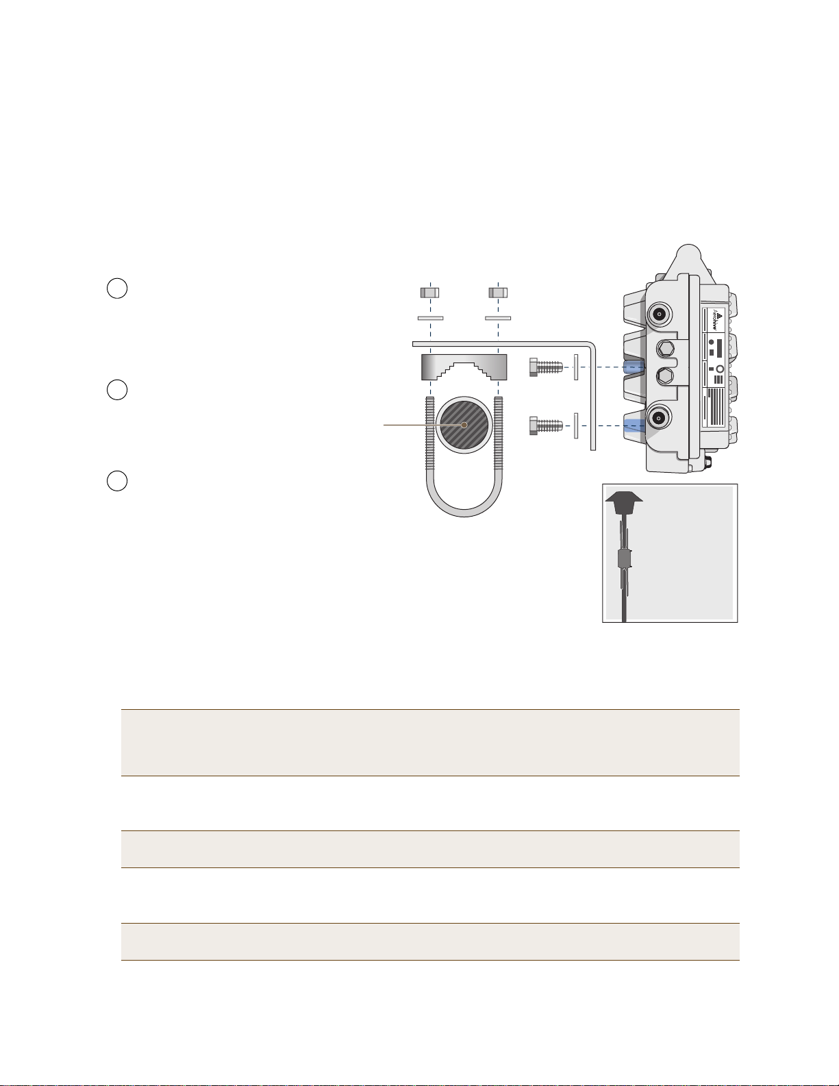
Note: For clarity, only one post mounting
set is shown in the illustration. You also
need to use a second set to finish mounting
the HiveAP on a pole.
Use the 1/4-20 bolts and split
washers to attach the shorter end of
the L-shaped bracket to holes in the
underside of the HiveAP 28.
Slip the U-bolt around the pole and
thread its ends through the saddle
clamp and L-shaped bracket.
Thread the split washers and
5/16-18 nuts over the ends of the
U-bolt and tighten until the bracket
assembly and device are secured to
the pole.
1
2
3
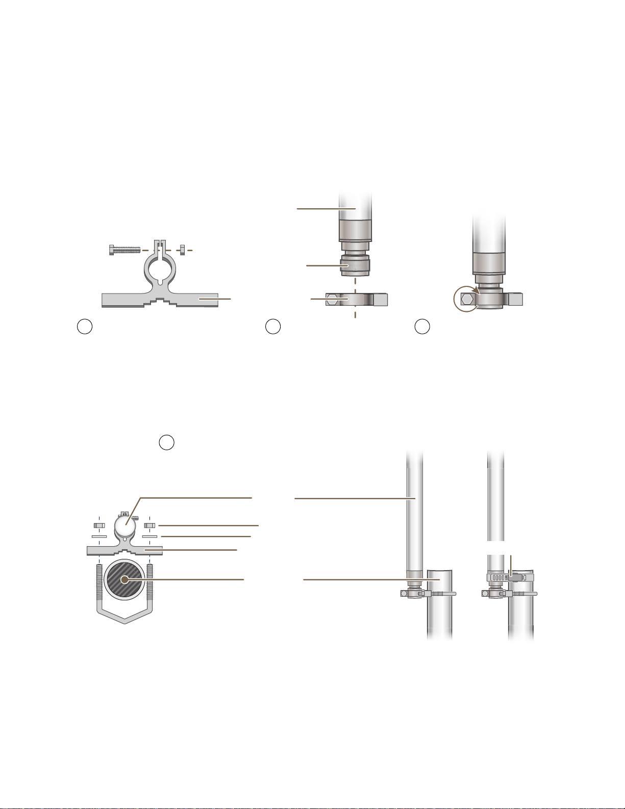
Pole Mount
To mount the HiveAP 28 to a pole with a 1.5-inch diameter, you need two sets of the L-shaped brackets, two 2"
U-bolts, saddle clamps, and the nuts, bolts, and washers shown in Figure 5. You also need a wrench to tighten the
nuts and bolts securely.
Figure 5 Attaching the HiveAP 28 to a Pole
Bird’s-Eye View
5/16-18 Nuts
Split Washers
L-Shaped Bracket
Saddle Clamp
Vertical Pole
(1.5” diameter)
2” U-Bolt
1/4-20 Bolts
and
Split Washers
5 GHz 2.4 GHz
Side view of the
HiveAP 28
mounted to a
street light
1. Align two of the holes in the short er end of th e bracket with tw o of the ho les in the HiveAP, insert the two bolts
through the washers and bracket, and screw them into the holes in the HiveAP 28 chassis, using a wrench to
tighten the bolts so that the bracket is securely attached.
Note: Repeat this step to attach the other br acket to the HiveAP. However, this time, place the long end of
the bracket in the opposite direction of the first one for better stability. For example, if you attached
2. Holding a saddle clamp against the inside of the long end of one of the L-shaped brackets, slip a U-bolt around
3. Thread a split washer and 5/16-18 nut to each end of the U-bolt, and ti ghte n them with a wre nch to secu re the
Deployment Guide 41
the first bracket with its long end positioned toward the outside edge of the device, install this second
bracket with the long end of the bracket toward the middle.
the pole and thread it through the two holes in the saddle clamp and L-shaped bracket.
Note: One of the holes in the bracket is arc-shaped so that you can adjust the angle of the mounted device if
necessary.
U-bolt firmly to the pole.
Note: Repeat steps 2 and 3 to attach the other U-bolt and saddle clamp to the remaining L-shaped bracket
and secure the HiveAP 28 to the pole.
Page 22
Chapter 3 The HiveAP 28 Outdoor Platform
5 GHz 2.4 GHz
Strand Clamp
Split Washer
Strand
1/4-20 Bolt
End View
Side View
Side view of the
HiveAP 28 mounted
on a cable strand
90-Degree
Type N Adapter
90-Degree
Type N Adapter
2.4 GHz Antennas
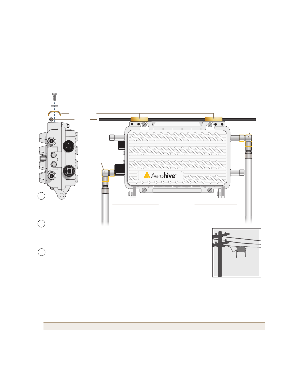
Note: For clarity, only one bolt, washer,
and strand clamp are shown in the
illustration on the left. Y ou also need to use
a second set of these items to finish
clamping the HiveAP to a wire strand.
Position the HiveAP 28 so that
its long side is directly beneath
a cable or wire strand.
Place the strand clamps over the
wire, and bolt the clamps tightly to
the chassis around the strand.
1
2
Attach 90-degree type N adapters to the
2.4 GHz antenna connectors so that the
adapters face downward, and then
attach the antennas to the adapters
3
Strand Mount
The HiveAP 28 outdoor platform can also be mounted on a cable or strand of wire as shown in Figure 6. When
mounted on a wire strand, use 90-degree N type adapters (not in cluded) to orient the a ntennas verti cally. If you do
not use the adapters and orient the antennas horizontally, the area covered will be far less.
Figure 6 Clamping the HiveAP 28 to a Wire Strand
To mount the HiveAP 28 on a wire or strand, you need a wrench and two 1/4-20 bolts, split washers, strand clamps,
and 90-degree type N adapters. In the following instructions, you use only the 2.4 GHz antennas.
1. Position the HiveAP 28 so that its long side (with three holes at each end) is underneath a cable or wire strand
running lengthwise along the upper side of the chassis (for the proper orientation, see the inset in Figure 6).
2. Place the strand clamp over the wire and use the 1/4-20 bolt and split washer to secure the strand betw een the
clamp and chassis.
Note: Repeat the preceding steps to fasten the other end of the HiveAP 28 to the cable or wire strand.
3. Attach the 90-degree type N adapters to the two 2.4 GHz an tenna connectors and then attach the antennas to
the adapters so that the antennas face downward. For details, see "Attaching Anten nas" on page 44.
42 Aerohive
Page 23
MOUNTING THE HIVEAP 28 AND ATTACHING ANTENNAS
5 GHz 2.4 GHz
7 7/8”
200 mm
Top of Wall
5 GHz 2.4 GHz
Mounting Plate
1/4-20 x 1/2”
Flat Head Screws
Bird’s-Eye View
Side view of the
HiveAP 28 mounted
on an exterior wall
Guide the screws fastened to
the wall through the keyholes
in the mounting plates.
Attach four screws to a secure object
such as a wall or beam. Space them
8 1/8" (206 mm) apart vertically and
7 7/8" (200 mm) apart horizontally.
With the ridged edge of the holes on the
mounting plates facing the HiveAP 28, use
1/4-20 x 1/2 inch screws to secure the two
mounting plates to its underside.
1 2 3
Note: For clarity, only one mounting plate is shown in the illustration.
You also need a second plate with another set of screws.
Surface Mount
You can use the mounting plate to attach the HiveAP 28 to any surface that supports its weight (9 lbs., 4.08 kg), and
to which you can screw or nail the plate. First, mount the plate to the HiveAP 28, and then attach the plate to the
surface, as shown in Figure 7. Note that the screw heads that you attach to the wall or surface must be small
enough for the keyholes on the mounting plate to slip over them.
Note: Because the metal in a wall can degrade the radio signal pattern, Aerohive recommends using sector
antennas instead of omnidirectional antennas when mounting the device on a wall.
Figure 7 Mounting the HiveAP 28 on a Wall
To mount the HiveAP 28 to a surface like a wall, you need two mounting plates, four 1/4-20 x 1/2" flat head screws,
four screws (no bigger than 5/16"), and a screw driver:
1. Align the ridged edge of one of the mounting plates with two of the holes located on the underside of the
HiveAP 28, and use two 1/4-20 x 1/2" flat head screws to secure the plate against the HiveAP 28. Then attach
the other mounting plate to the HiveAP 28 in the same way.
2. Attach four 5/16" screws to a wall or beam. They must be 8 1/8" (206 mm) apart vertically and 7 7/8" (200 mm)
apart horizontally to accommodate the keyholes on the mounting plates.
3. Guide the keyholes over the screws fastened to the wall and push downwa rd after the screw heads have cle ared
the keyholes.
Deployment Guide 43
Page 24

Chapter 3 The HiveAP 28 Outdoor Platform
Attaching Antennas
You can connect the antennas directly to the HiveAP 28 or mount them separately. Although connecting the
antennas directly to the device typically provides better performance, in some cases the location of the HiveAP
might not be a good location for the antennas; for example, if the HiveAP 28 is mounted on a reinforced concrete
wall that interferes w ith radio coverage. In such cases, mounting the antennas separately in a more open location
can improve coverage; however, bear in mind that cables introduce loss into the overall signal strength and that the
longer the cable connecting the antennas to the HiveAP 28, the greater the loss will be.
Note: Cover any unused an tenna connectors with a connector cap to prevent water intrusion and possible safety
hazards.
Connecting Antennas Directly to the HiveAP 28
The two 2.4 GHz and two 5 GHz antennas that ship with the HiveAP 28 have male Type N connectors that you can
connect directly to the female Type N antenna connectors on the HiveAP 28. You can also use self-amalgamating
PTFE (polytetrafluoroethylene) tape, which is available separately from Aerohive, to create a w aterproof seal at the
points of attachment.
To attach the antennas:
1. Remove the antenna connector covers from the HiveAP 28 (leave the covers on any connectors that you do not
plan to use), and make sure that the surface of the connectors on the HiveAP 28 and the connectors on the
antennas are clean.
2. If you are using PTFE tape, wrap the tape around the threads on the HiveAP 28 antenna connectors as follows:
2.1. Starting at one end of the threads on one of the connectors, stretch the tape and wrap it in half-lap
layers until you cover the threads completely.
2.2. Wrap the tape in the opposite direction to bring it back onto itself for one full wrap.
2.3. Place one thumb on the tape at the point of termination and stretch the tape until it breaks.
2.4. Repeat the preceding steps to cover all the connectors to which you will attach antennas.
3. Connect the 2.4 GHz antennas to the 2.4 GHz antenna connectors. (To tighten an antenna, turn the antenna
base cap—the textured metal band that encloses the connector—clockwise over the tape-covered threads of the
HiveAP antenna connector.)
Their connections are now sealed and waterproof.
4. Repeat the preceding steps to connect the 5 GHz antennas.
Mounting Antennas Separately
In addition to connecting antennas directly to the HiveAP 28, you can also mount them separately and run a cable
between the antennas and the device. Use either male-to-female cables with Type N connectors or use
male-to-male or female-to-female cables with cable gender changers. (The antennas have male Type N connectors
and the HiveAP 28 has female Type N connectors.)
Note: Using cables to mount antennas separately causes some signal loss and using a cable gender changer can
cause even more. The amount of loss varies from product to product, so refer to the documentation
accompanying the cables and gender changer you use for information. To minimize loss, Aerohive
recommends using LMR400 cables and using the shortest cables possible.
44 Aerohive
Page 25
MOUNTING THE HIVEAP 28 AND ATTACHING ANTENNAS
Attachment Clamp
Base Cap
Antenna
1 3/8”
Bolt
Nut
Use one wrench to hold the nut
in place and the other to tighten
the bolt.
Insert the antenna into the clamp
until it grips the base cap.
Insert the bolt through the attachment
clamp and hold it in place with the nut.
Do not tighten it yet.
1 2 3
Nonmetallic Pole
(2” diameter)
Antenna
Hose Clamp
Bird’s-Eye View
V-Bolt
Side View
Nuts
Washers
Attachment Clamp
With the attachment clamp against one side of the pole,
insert the V-bolt through the two holes in the clamp from
the other side. Then thread washers and nuts over the two
ends of the bolt and tighten them in place with a wrench.
4
Note: Aerohive recommends attaching the antenna near
the top of the pole. If you need to improve the stability of
the mounted antenna, fasten it to the pole with a hose
clamp (included) as shown on the far right.
or
You can mount antennas at the top of a pole as shown in Figure 8 and Figure 9, or to a flat surface. If you must
mount the antenna lower on a pole, the pole must be nonmetallic—such as one made from a hard plastic like PVC
(polyvinyl chloride)—so that it does not distort the signal. Aerohive recommends that antennas be installed away
from power lines and obstructions that can interfere with radio coverage.
For each antenna that you mount, you need an attachment clamp, a 1 3/8" bolt and nut, a V-bolt, two washers and
two nuts, a hose clamp, and two wrenches.
Figure 8 Securing an Antenna to an Attachment Clamp
1. Insert the 1 3/8" bolt through the attachment clamp and screw a nut loosely onto its end.
2. Place the antenna base cap inside the attachment clamp.
3. Using a pair of wrenches, tighten the nut to the bolt until the clamp grips the base cap firmly.
Figure 9 Mounting an Antenna to a Pole
4. To mount the antenna on a nonmetallic pole, place the attachment clamp against the pole, thread the V-bolt
through the holes on the attachment, the washers, and nuts, and use the wrenches to tighten the nuts to the
bolt. (Optional) For added stability, fasten the top of the antenna to the pole with the hose clamp.
To mount the antenna directly to a flat surface, run bolts or screws (not included) through the two holes in the
attachment clamp, and fasten them firmly to the surface.
Deployment Guide 45
Page 26
Chapter 3 The HiveAP 28 Outdoor Platform
Note: Radio coverage might be limited if the surface acts as an obstruction.
5. Make sure that all the antenna and cable connectors are clean. If you are using PTFE tape, wrap the tape around
the threads on the HiveAP 28 antenna connectors as explained in "Connecting Antennas Directly to the HiveAP
28" on page 44.
6. Assuming that you are using male-to-female cables, connect the female Type N connector on the cables to the
male connectors on the antennas.
7. Connect the male Type N connectors on the cables to the female antenna connectors on the HiveAP 28.
DEVICE, POWER, AND ENVIRONMENTAL SPECIFICATIONS
Understanding the range of specifications for the HiveAP is necessary for optimal deployment and device operation.
The following specifications describe the physical features and hardware components, the power adapter and PoE
(Power over Ethernet) electrical requirements, and the temperature and humidity ranges in which the device can
operate.
Device Specifications
• Chassis dimensions: 13 13/16" W x 4 3/8" H x 8 3/8" D (35 cm W x 11 cm H x 21 cm D)
• Weight: (9 lbs., 4.08 kg)
• Antennas: Two detachable single-band 8dBi 802.11b/g antennas and two detachable single-band 10dBi 802.11a
antennas
• Maximum Transmission Power: 20 dBm
• Ethernet port: autosensing 10/100Base-T/TX Mbps, with IEEE 8 02.3af-compliant PoE (Power over Ethernet)
Power Specifications
• AC/DC power adapter:
• Input:100 – 240 VAC
• Output: 17 watts
• PoE nominal input voltages: 48 V, 0.35A
• RJ-45 power input pins: Wires 4, 5, 7, 8 or 1, 2, 3, 6
•RF power output:
802.11b RF (8-dBi Omnidirectional Antenna, Model S2406BFNM)
Frequency 2412 MHz 2437 MHz 2462 MHz
Peak Power Output (dBm) 14.20 14.00 14.20
802.11g RF (8-dBi Omnidirectional Antenna, Model S2406BFNM)
Frequency 2412 MHz 2437 MHz 2462 MHz
Peak Power Output (dBm) 16.20 16.80 15.00
802.11a RF (10-dBi Omnidirectional Antenna, Model S4908WBF)
Frequency 5745 MHz 5785 MHz 5825 MHz
Peak Power Output (dBm) 17.80 17.40 17.60
Environmental Specifications
• Operating temperature: -40 to 140 degrees F (-40 to 60 degrees C)
• Storage temperature: -40 to 194 degrees F (-40 to 90 degrees C)
• Relative Humidity: Maximum 100%
46 Aerohive
Page 27

Chapter 4 The HiveAP 340 Platform
The Aerohive HiveAP 340 is a high-performance and highly reliable 802.11n wireless access point. The HiveAP 340
provides dual concurrent 802.11b/g/n and 802.11a/n radios for 3x3 MIMO (Multiple In, Multiple Out) and dual
10/100/1000 Ethernet ports for link aggregation or link redundancy. Its power management system uses a concept
called smart PoE (Power over Ethernet) to adjust its power consumption automatically in response the available
power in different environments. Smart PoE supports the IEEE 802.3af standard and the 802.3at pre-standard.
This chapter covers the following topics relating to the HiveAP 340:
• "HiveAP 340 Pro duct Overview" on page 48
• "Ethernet and Console Ports" on page 50
• "Status LEDs" on page 54
• "Antennas" on page 54
• "Mounting the HiveAP 340" on page 58
• "Ceiling Mount" on page 58
• "Surface Mount" on page 60
• "Device, Power, and Environmental Specifications" on page 61
Deployment Guide 47
Page 28
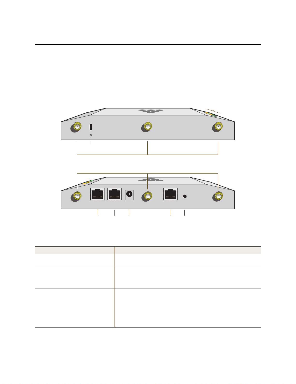
Chapter 4 The HiveAP 340 Platform
Power
Connector
10/100 /1000
Mbps PoE Ports
Reset
Button
Console
Port
Device
Lock Slot
Status LEDs
802.11b/g/n RP-SMA Connectors for Detachable Single-Band Antennas
802.11a/n RP-SMA Connectors for Detachable Single-Band Antennas
HIVEAP 340 PRODUCT OVERVIEW
The HiveAP 340 is a multi-channel wireless access point. It is compatible with IEEE 802.11b/g/n (2.4 GHz) and IEEE
802.11a/n (5 GHz) standards and supports a variety of Wi-Fi (wireless fidelity) security protocols, including WPA
(Wi-Fi Protected Access) and WPA2.
You can see the hardware components on the HiveAP in Figure 1. Each component is described in Table 1.
Figure 1 HiveAP 340 Hardware Components
5 GHz (B)5 GHz (C)
2.4 GHz (A) 2.4 GHz (B) 2.4 GHz (C)
ETH0
ETH1
48V DC
(.625A)
CONSOLE
RESET
5 GHz (A)
Table 1 HiveAP 340 Component Descriptions
Component Description
Status LEDs The status LEDs convey operational states for system power, firmware,
Ethernet interfaces, and radios. For details, see "Status LEDs" on page 54.
Device Lock Slot You can physically secure the HiveAP by attaching a lock and cable (such
as a Kensington® notebook lock) to the device lock slot or by using the
lock adapter that is included in the mounting kit and a padlock. For more
information, see "Locking the HiveAP 340" on page 59.
802.11a/b/g/n RP-SMA Connectors You can connect up to six detachable single-band antennas to the male
802.11a/b/g/n RP-SMA (reverse polarity-subminiature version A)
connectors. Connect the longer antennas, which support 2.4 GHz
frequencies (for IEEE 802.11b/g/n), to the connectors on the side panel
with the Ethernet ports. Connect the shorter antennas, which support 5
GHz frequencies (for IEEE 802.11a/n), to the connectors on the side pane l
with the device lock slot. For details, see "Antennas" on page 54.
48 Aerohive
Page 29

HIVEAP 340 PRODUCT OVERVIEW
Component Description
10/100/1000 Mbps PoE Ports The two 10/100/1000-Mbps Ethernet ports—ETH0 and ETH1—support IEEE
802.3af and 802.3at PoE (Power over Ethernet) and receive RJ-45
connectors. The HiveAP can receive power through one or both Ethernet
connections from PSE (power sourcing equipment) that is compatible with
the 802.3af standard and the forthcoming 802.at standard, such as one of
the PoE injectors available as an optional accessory from Aerohive. (If you
connect the HiveAP to a power source through the power connector and
PoE ports simultaneously, the device draws power through the power
connector and automatically disables PoE.)
You can configure ETH0 and ETH1 as two individual Ethernet interfaces,
combine them into an aggregate interface to increase throughput, or
combine them into a redundant interface to increase reliability. You can
connect the HiveAP 340 to a wired network or to a wired device (such as
a security camera) through these ports using bridging. They are
compatible with 10/100/1000Base-T/TX and automatically negotiate
half- and full-duplex conn ections with the connecting device. They are
autosensing and adjust to straight-through and cross-over Ethernet cables
automatically. For details, see "Ethernet and Console Ports" on page 50.
Power Connector The 48-volt DC power connector (0.625 amps) is one of two methods
through which you can power the HiveAP 340. To connect it to a 100 –
240-volt AC power source, use the AC/DC power adaptor tha t is available
as an extra option. Because the HiveAP does not have an on/off switch,
connecting it to a power source automatically powers on the device.
Console Port You can access the CLI by making a serial connection to the RJ-45 console
port. The management station from which you make a serial connection
to the HiveAP must have a VT100 emulation program, such as Tera Term
©
(a free terminal emulator) or Hilgraeve Hyperterminal® (provided
Pro
with Windows® operating systems). The following are the serial
connection settings: bits per second: 9600, data bits: 8, parity: none,
stop bits: 1, flow control: none. For details, see "Ethernet and Console
Ports" on page 50.
Reset Button The reset button allows you to reboot the device or reset the HiveAP to
its factory default settings. Insert a paper clip , o r som et hing sim ilar, into
the Reset pinhole and press the reset button. To reboot the device, hold
the button down between 1 and 5 seconds. To return the configuration to
the factory default settings, hold it down for at least 5 seconds. After
releasing the button, the Power LED goes dark as the system reboots.
Then it pulses green while the firmware loads and the system performs a
self-test. After the software finishes loading, the Power LED glows steady
green.
To disable the reset button from resetting the configuration, enter this
command: no reset-button reset-config-enable Pressing the
button between 1 and 5 seconds will still reboot the Hive AP, but pressing
it for more than 5 seconds will not reset its configuration.
Note: The rear surface of the HiveAP 340 is used for heat dissipation to reduce the internal temperature.
Consequently, it can become hot, so use caution when handling it.
Deployment Guide 49
Page 30

Chapter 4 The HiveAP 340 Platform
ETH0
Pin T568A Wire Color
1 White/Green
2 Green
3 White/Orange
4Blue
5 White/Blue
6 Orange
7 White/Brown
8Brown
(View of the ETH0 PoE
Port on the HiveAP 340)
8 1
Pin Numbers
Pin T568B Wire Color
1 White/Orange
2 Orange
3 White/Green
4Blue
5 White/Blue
6 Green
7 White/Brown
8Brown
T568A-T erminated Ethernet Cable
with an RJ-45 Connector
802.3af Alternative A
(Data and Power on
the Same Wires)
802.3af Alternative B
(Data and Power on
Separate Wires)
802.3at Wiring Options
Pin Data Signal MDI MDI-X MDI or MDI-X 1 2 3 4
1 Transmit + DC+ DC– – – – DC1+ DC1– DC1+ DC1–
2 Transmit - DC+ DC– – – – DC1+ DC1– DC1+ DC1–
3 Receive + DC– DC+ – – – DC1– DC1+ DC1– DC1+
4 (unused) – – – – – – DC+ DC2+ DC2+ DC2– DC2–
5 (unused) – – – – – – DC+ DC2+ DC2+ DC2– DC2–
6 Receive - DC– DC+ – – – DC1– DC1+ DC1– DC1+
7 (unused) – – – – – – DC– DC2– DC2– DC2+ DC2+
8 (unused) – – – – – – DC– DC2– DC2– DC2+ DC2+
MDI = Medium dependent interface for straight-through connections
MDI-X = Medium dependent interface for cross-over (X) connections
The PoE ports are auto-sensing and can automatically adjust to transmit and receive data over straight-through or cross-over Etherne
connections. L kewise, they can automatically adjust to 802.3af Alternative A and B power delivery methods. Furthermore, when the
Alternative A method is used, the ports automatically allow for polarity reversals depending on their role as either MDI or MDI-X. In
802.3at, the 1/2 and 3/6 wire pairs connect to DC source 1 and 4/5 and 7/8 pairs to DC source 2 in PSE. Although the exact polarity
depends on the PSE design, the HiveAP 340 Ethernet ports can support all possible options.
T568B -terminated Ethernet Cable
with an RJ-45 Connector
T568A and T568B are two standard
wiring termination schemes. Note that
the only difference between them is
that the white/green + solid green pair
of wires and the white/orange + solid
orange pair are reversed.
For straight-through Ethernet
cables—using either the T568A or
T568B standard—the eight wires
terminate at the same pins on each
end.
For cross-over Ethernet cables, the
wires terminate at one end according
to the T568A standard and at the
other according to T568B.
Ethernet and Console Ports
There are three ports on the HiveAP 340: two RJ-45 10/100/1000Base-T/TX Ethernet ports and an RJ-45 console port.
The pin assignments in the PoE (Power over Ethernet) Ethernet ports follow the TIA/EIA-568-B standard (see
Figure 2). The ports accept standard types of Ethernet cable—cat3, cat5, cat5e, or cat6—and can receive power
over this cable from power sourcing equipment (PSE) that is 802.3af-compatible. If you use cat5, cat5e, or cat6
cables, the HiveAP 340 can also support 802.3at-compliant PSE. Such equipment can be embedded in a switch or
router, or it can come from purpose-built devices that inject power into the Ethernet line en route to the HiveAP.
Because the PoE ports have autosensing capabilities, the wiring termination in the Ethernet cable can be either
straight-through or cross-over.
Figure 2 PoE Wire Usage and Pin Assignments
50 Aerohive
Page 31

HIVEAP 340 PRODUCT OVERVIEW
Smart PoE
The HiveAP 340 applies the Aerohive concept of smart PoE to adjust power consumption as necessitated by varying
levels of available power. No adjustments are needed when the power level is 17.5 W (watts) or higher. If the
available power drops to a range between 16 and 17.5 W, the HiveAP disables the ETH1 interface. If the level drops
to the 14.4 – 16 W range, it then switches from 3x3 MIMO (Multiple In, Multiple Out) to 2x3 (see "MIMO" on page 55).
In rare cases when the power drops betwee n 12 and 14.4 W and further power conservation is ne cessary, the HiveAP
reduces the speed on ETH0 from 10/100/1000 Mbps to 10/100 Mbps. Finally, in the event that there is a problem
with the PoE switch or Ethernet cable and the power falls between 0 and 12 W, the HiveAP disables its wireless
interfaces and returns its ETH0 and ETH1 interfaces to 10/1 00 /1 00 0 Mbps sp eed s. Throu gh the appl icatio n of sma rt
PoE, the HiveAP 340 can make power usage adjustments so that it can continue functioning even when the available
power level drops.
Aggregate and Redundant Interfaces
By default ETH0 and ETH1 act as two individual Ethernet interfaces. When both interfaces are connected to the
network and are in backhaul mode, the HiveAP transmits broadcast traffic only through ETH0. The HiveAP transmits
broadcast traffic through ETH1 only when ETH0 does not have network connectivity. When both Ethernet interfaces
are connected to the network and are in access mode, then the HiveAP transmits broadcast traffic through all the
access interfaces: ETH0, ETH1, and all wireless subinterfaces in access mode.
In addition to using ETH0 and ETH1 as individual interfaces, you can combine them into an aggregate interface
(agg0) to increase throughput, or combine them into a redundant interface (red0) to increase reliability. The logical
red0 and agg0 interfaces support all the settings that you can configure for Ethernet interfaces except those
pertaining to physical link characteristics such as link speed. See the sections below for configuration information.
Aggregate Interface
You can increase throughput onto the wired network by combining ETH0 and ETH1 into a single logically aggregated
interface called "agg0". The aggregate interface effectively doubles the bandwidth that each p hysi cal in terface has
when used individually. In this configuration, both Ethernet ports actively forward traffic, the HiveAP applying an
internal scheduling mechanism based on the source MA C address of each packet to send traffic through the
aggregate member interfaces. To configure an aggregate interface, enter the following commands:
interface eth0 bind agg0
interface eth1 bind agg0
In addition to configuring the HiveAP, you must also configure the connecting switch to support EtherChannel. For
example, the following commands bind two physical Ethernet ports—0/1 and 0/2—to the logical interface
port-channel group 1 on a Cisco Catalyst 2900 switch running Cisco IOS 12.2:
Switch#conf t
Switch(config)#interface port-channel 1
Switch(config-if)#switchport mode access
Switch(config-if)#spanning-tree portfast
Switch(config-if)#exit
Switch(config)#interface fastEthernet 0/1
Switch(config-if)#switchport mode access
Switch(config-if)#channel-group 1 mode on
Switch(config-if)#spanning-tree portfast
Switch(config-if)#exit
Deployment Guide 51
Page 32

Chapter 4 The HiveAP 340 Platform
Switch(config)#int fastEthernet 0/2
Switch(config-if)#switchport mode access
Switch(config-if)#channel-group 1 mode on
Switch(config-if)#spanning-tree portfast
Switch(config-if)#exit
Switch(config)#exit
Switch#wr mem
Finally, you must cable the Cisco switch and the HiveAP together: Cisco 0/1 to HiveAP eth0, and Cisco 0/2 t o HiveAP
eth1.
Redundant Interface
If a single Ethernet link provides sufficient bandwidth and speed, such as a 1000 Mbps link, but you want to ensure
link redundancy, you can connect the two Ethernet ports to the same switch—or to two different switches—and
configure them to act as a redundant interface called "red0". In this mode, only one Ethernet interface is actively
forwarding traffic at any one time. If eth0 is active and eth1 is passive and eth0 loses its connection, the HiveAP
switches over to eth1. To configure a redundant interface, enter the following commands:
interface eth0 bind red0 primary
interface eth1 bind red0
The interface that you specify as primary is the one that the HiveAP uses when both interfaces have network
connectivity. Because the HiveAP uses eth0 as the primary interface by default, it is unnecessary to specify
"primary" in the first command above. However, it is included to make the role of eth0 as the primary interface
obvious.
Note: No extra configuration is necessa ry on the connecting switch or switches to support a redundant interface.
Interface Selection for the Default Route
In cases where there are multiple active interfaces in backhaul mode, the HiveAP uses the following logic to choose
which interface to use in its default route:
• If there is an Ethernet interface and a wireless interface in backhaul mode, the HiveAP uses the Ethernet
interface in its default route.
• If there are multiple Ethernet interfaces in backhaul mode, the HiveAP chooses which one to use in its default
route in the following order:
• It uses red0 or agg0 if one of them has at least one member interface bound to it and its link state is UP.
• It uses ETH0 if neither red0 nor agg0 has any member interfaces and the link state for ETH0 is UP.
• It uses ETH1 if neither red0 nor agg0 has any member interfaces, the link state for ETH0 is DOWN, and the
link state for ETH1 is UP.
52 Aerohive
Page 33
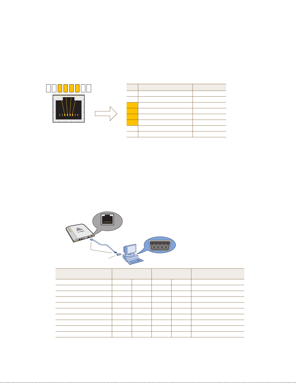
Console Port
Pin Signal Direction
1 RTS (Request to Send) Output, unused
2 DTR (Data Terminal Ready) Output, unused
3 TXD (Transmitted Data) Output
4 Ground Ground
5 Ground Ground
6 RXD (Received Data) Input
7 DSR (Data Set Ready) Input, unused
8 CTS (Clear to Send) Input, unused
RJ-45 Console Port
(View of the console
port on the HiveAP)
Because this is a console port, only pins 3, 4, 5, and 6 are currently in use.
Console Port Pin Assignments
6 13457 28
Rollover Cable with
RJ-45 Connectors
RJ-45-to-Female DB-9 Adapter
Console Port
COM Port
(on Back Panel)
CONSOLE
Management System
HiveAP 340
Console Port
(HiveAP 340)
RJ-45-to-RJ-45
Rollover Cable
RJ-45-to-Female
DB-9 Adapter
Management
System
Signal RJ-45 Pin RJ-45 Pin RJ-45 Pin DB-9 Pin Signal
RTS (Request to Send) 1 8 1 8 CTS (unused)
DTR (Data Terminal Ready) 2 7 2 6 DSR (unused)
TXD (Transmitted Data) 3 6 3 2 RXD
Ground 4 5 4 5 Ground
Ground 5 4 5 5 Ground
RXD (Received Data) 6 3 6 3 TXD
DSR (Data Set Ready) 7 2 7 4 DTR (unused)
CTS (Clear to Send) 8 1 8 7 RTS (unused)
- - - - 9 RI (Ring Indicator, unused)
The pin-to-signal mapping in the RJ-45 console port is shown shown in Figure 3.
Figure 3 Console Port Pin Assignments
CONSOLE
HIVEAP 340 PRODUCT OVERVIEW
To make a serial connection between your management system and the HiveAP, you can use the console cable that
is available as an extra option. Insert the RJ-45 connector into the HiveAP 340 console port, and attach the DB-9
connector to the serial (or COM) port on your management system. The management system must have a VT100
terminal emulation program, such as Tera Term Pro
(provided with Windows
Figure 3.
Figure 4 Wiring Details for Making a Serial Cable with an RJ-45-to-Female DB-9 Adapter
©
®
operating systems). If you want to make your own serial cable and adapter, refer to
(a free terminal emulator) or Hilgraeve Hyperterminal®
Deployment Guide 53
Page 34

Chapter 4 The HiveAP 340 Platform
Status LEDs
The five status LEDs on the top of the HiveAP 340 indicate various states of activity through their color (dark, green,
amber, and red) and illumination patterns (steady glow or pulsing). The meanings of the various color + illumination
patterns for each LED are explained below.
Power
•Dark: No power
• Steady green: Powered on and the firmware is running normally
• Pulsing green: Firmware is booting up
• Steady amber: Firmware is being updated
• Pulsing amber: Alarm indicating a firmware issue has occurred
• Steady red: Alarm indicating a hardware issue has occurred
ETH0 and ETH1
• Dark: Ethernet link is down or disabled
• Steady green: 1000 Mbps Ethernet link is up but inactive
• Pulsing green: 1000 Mbps Ethernet link is up and active
• Steady amber: 10/100 Mbps Ethernet link is up but inactive
• Pulsing amber: 10/100 Mbps Ethernet link is up and active
WIFI0 and WIFI1
• Dark: Wireless interface is disabled
• Steady green: Wireless interface is in access mode but inactive
• Pulsing green: Wireless interface is in access mode and active
• Steady amber: Wireless interface is in backhaul mode but inactive
• Pulsing amber: Wireless interface is in backha ul mode and is connected with other hive members
• Alternating green and amber: Wireless interface is in backhaul mode and is searching for other hive
members
Antennas
Antennas are an integral part of the HiveAP 340. The HiveAP 340 can accept up to six detachable dipole antennas.
The three shorter antennas are designed for the 5 GHz band and have a 2-dBi gain. The three longer antennas are
designed for the 2.4 GHz band and have a 4.9-dBi gain. These antennas are omnidirectional, providing fairly equal
coverage in all directions in a toroidal (donut-shaped) pattern around each antenna (see Figure 4 on page 30). For
greater coverage on a horizontal plane, it is best to orient the antennas vertically. So that you can easily do that
whether the HiveAP chassis is mounted horizontally or vertically, the antennas hinge and swivel (see Figure 5 on
page 55.)
Although hive members automatically adjust their signal strength according to their environments, you can resize
the area of coverage by increasing or decreasing the signal strength manually by entering the interface {
wifi0 | wifi1 } radio power <number> command, where <number> can be from 1 to 20 and represents
a value in dBm.
54 Aerohive
Page 35
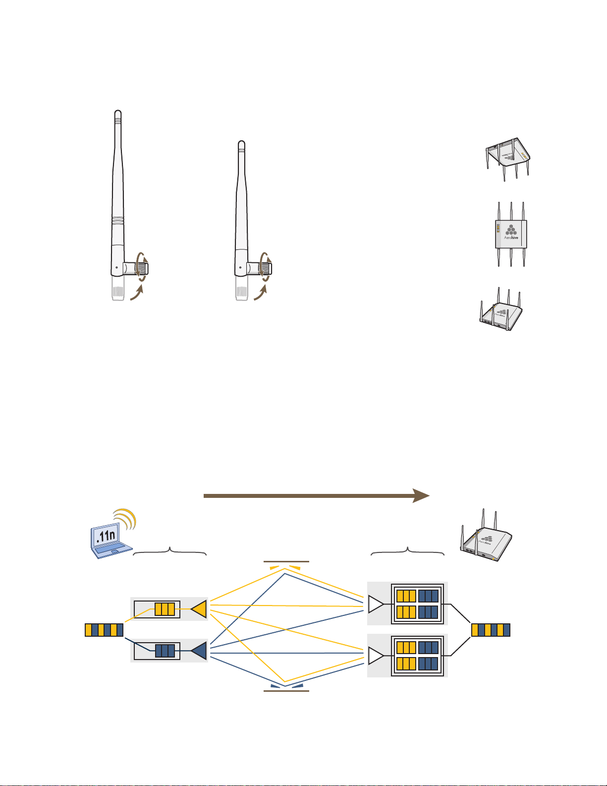
Figure 5 HiveAP 340 Antennas
The base of the antennas hinge up to 90 degrees so that you
can orient the antennas independently of the orientation of
the HiveAP chassis. The antennas also rotate in a full circle.
When mounting the HiveAP
340 on a ceiling, orient its
antennas downward.
When mounting the HiveAP
on a wall or post, fully extend
its antennas upward and
downward.
When mounting the HiveAP
above a ceiling or on a
horizontal beam, orient its
antennas upward.
Generally, orient the antennas vertically for
improved radio coverage, as shown here:
HIVEAP 340 PRODUCT OVERVIEW
2.4 GHz Antenna for
IEEE 802.11b/g/n
Length when fully
extended: 7 7/8” (20 cm)
5 GHz Antenna for IEEE
802.11a/n
Length when fully
extended: 5 15/16” (15 cm)
MIMO
MIMO (Multiple In, Multiple Out) is a major WLAN advancement introduced in the IEEE 802.11n standard in which
multiple RF links are formed on the same channel between the transmitter and receiver simultaneously. To
accomplish this, the transmitter separates a single data stream into multiple spatial s treams, one for ea ch RF ch ain
(an antenna + various digital signal processing modules linked to the antenna). The transmit antennas at the end of
each RF chain then transmit their spatial streams. The recipient’s receive antennas obtain streams from all the
transmit antennas. In fact, due to multipath, they receive multiple streams from each transmit antenna. The
receive antennas pass the spatial streams to the digital signal processors in their RF chains, which take the best data
from all the spatial streams and reassemble them into a single data stream once again (see Figure 6).
Figure 6 2x2 MIMO (2 Transmit Antennas x 2 Receive Antennas)
802.11n wireless client
with two antennas
HiveAP 340 using
two antennas
RF Chains RF Signals (Multipath)
Digital Signal
Processors
Data
Transmit
Antennas
Deployment Guide 55
RF Chains
Object
Receive
Antennas
Digital Signal
Processors
Reassembled
Data
Page 36
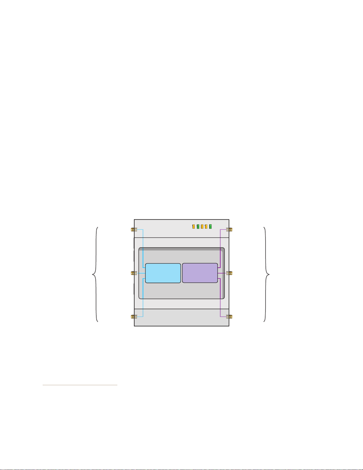
Chapter 4 The HiveAP 340 Platform
PWR
ETH1
ETH0
WIFI1
WIFI0
Radio 1
RF 802.11b/g/n
2.4 GHz
Radio 2
RF 802.11a/n
5 GHz
2.4 GHz (A)
2.4 GHz (B)
2.4 GHz (C)
5 GHz (A)
5 GHz (B)
5 GHz (C)
RP-SMA
Connectors
RP-SMA
Connectors
Cut-away view of the HiveAP 340 to show the relationship of the antennas and the two internal radios
In previous 802.11 standards, access points and clients each employed a single set of components, or RF chain, for
transmitting or receiving. Although two antennas are often used for diversity, only the one with the best
signal-to-noise ratio is used at any given moment, and that antenna makes use of the single RF chain while the other
antenna remains inactive. A significant improvement that MIMO introduces is to permit each antenna to have its
own RF chain and for all antennas to function simultaneously. For the HiveAP 340, you can connect up to three
antennas per radio and configure the radio to use two or three transmit chains and two or three receive chains.
1
Using two or three transmit and receive chains simultaneously increases the amount of data that can flow across the
WLAN and accelerates the processing of that data at each end of the wireless link.
Another major aspect of MIMO is how it turns multipath signals from a curse to a boon. As a radio signal moves
through space, some objects reflect it, others interfere with it, and still others absorb it. The receiver can end up
receiving multiple copies of the original signal, all kind of muddled together. However, the digital signal processors
in the multiple receive chains are able to combine their pro cessing efforts to sort thro ugh all the received data and
reconstruct the original message. Furthermore, because the transmitter makes use of multiple RF chains, there is
an even richer supply of signals for the receive chains to use in their processing. To set the transmit and receive RF
chains for a radio profile, enter the following commands:
radio profile <name> transmit-chain { 2 | 3 }
radio profile <name> receive-chain { 2 | 3 }
There are two sets of antennas—three antennas per set—that operate concurrently in two different frequency
ranges: 2.4 GHz (IEEE 802.11b/g/n) and 5 GHz (IEEE 802.11a/n). Using two different frequency ranges reduces the
probability of interference that can occur when numerous channels operate within the same range. Conceptually,
the relationship of antennas and radios is shown in Figure 7.
Figure 7 Antennas and Radios
The wifi0 interface links to radio 1 (frequency range = 2.4 GHz for IEEE 802.11b/g), and the wifi1 interface links to
radio
2 (frequency range = 5 GHz for IEEE 802.11a). These interface-to-radio relationships are permanent.
When deciding how many antennas to use, consider the types of wireless clients—802.11n only, 802.11g/n,
802.11b/g/n, or 802.11a/n—the area needing coverage, and the RF environment.
1. The convention for presenting the configuration of transmitting and receiving MIMO RF chains is TxR. For
example, a HiveAP 340 radio functioning in access mode might be configured to use two RF chains for
transmitting and three for receiving. In that case, its configuration can be presented as "2x3". In general, the
number of receive antennas is equal to or greater than the number of transmit antennas.
56 Aerohive
Page 37

HIVEAP 340 PRODUCT OVERVIEW
Using MIMO with Legacy Clients
In addition to supporting up to 300-Mbps throughput per radio for 802.11n clients, MIMO (Multiple In, Multiple Out)
can improve the reliability and speed of legacy 802.11a/b/g client traffic. When an 802.11a/b/g access point does
not receive acknowledgement that a frame it sent was received, it resends that frame, possibly at a somewhat
lower transmission rate. If the access point must continue resending frames, it will continue lowering its
transmission rate. As a result, clients that could get 54-Mbps throughput in an interference-free environment might
have to drop to 48- or 36-Mbps speeds due to multipath interface. However, because MIMO technology makes better
use of multipath, an access point using MIMO can continue transmitting at 54 Mbps, or at least at a better rate than
it would in a pure 802.11a/b/g environment, thus improving the reliability and speed of 802.11a/b/g client traffic.
Although 802.11a/b/g client traffic can benefit somewhat from an 802.11n access point using MIMO, supporting such
legacy clients along with 802.11n clients can have a negative impact on 802.11n client traffic. Legacy clients take
longer to send the same amount of data as 802.11n clients. Consequently, legacy clients consume more airtime than
802.11n clients do, causing greater congestion in the WLAN and reducing 802.11n performance.
By default, the HiveAP 340 supports 802.11a/b/g clients. Yo u can restrict access only to clients using the IEEE
802.11n standard. By only allowing traffic from clients using 802.11n, you can increase the overall bandwidth
capacity of the access point so that there will not be an impact on 802.11n clients during times of network
congestion. To do that, enter the following command:
radio profile <string> 11n-clients-only
You can also deny access just to clients using the IEEE 802.11b standard, which has the slowest data rates of the
three legacy standards, while continuing to support 802.11a and 802.11g clients. To do that, enter the following
command:
no radio profile <string> allow-11b-clients
By blocking access to 802.11b clients, their slower data rates cannot clog the WLAN when the amount of wireless
traffic increases.
Deployment Guide 57
Page 38

Chapter 4 The HiveAP 340 Platform
Mounting Plate
1
2
Press the track clips against the
ceiling track and swivel them until
they snap into place, gripping the
edges of the track.
If necessary, slide one or both of
the clips along the track to position
them at the proper distance (2 1/4”
or 7 cm) to fit through the holes in
the mounting plate.
Insert the mounting track over the
screws attached to the track clips,
and use the Keps nuts to fasten
the plate firmly to the screws on
the clips.
Use a wrench to tighten the nuts
firmly to the bolts and secure the
plate to the track.
3
Through the oblong opening in the
plate, drill a hole in the ceiling tile (not
shown). Then pass one or both
Ethernet cables through the hole, and
if you plan to supply power from an
AC power source rather than through
PoE, pass the power cable through
as well.
Drill a hole in the ceiling tile
and feed cables through here.
Ceiling Track
Track Clip
(worms’s eye view with ceiling
tiles removed for clarity)
2 1/4 “ (7 cm)
MOUNTING THE HIVEAP 340
Using the mounting plate and track clips, you can mount the HiveAP 340 to the tracks of a dropped ceiling grid.
Using just the mounting plate, you can mount the HiveAP to any surface that can support its weight (3.3 lb., 1.5 kg).
Ceiling Mount
To mount the HiveAP 340 to a track in a dropped ceiling, you need the mounting plate, two track clips, and two K eps
nuts, all of which ship as an option with the HiveAP 340. You also need a drill and—most likely—a ladder.
Nudge the ceiling tiles slightly away from the track to clear some space. Attach the track clips to the ceiling track,
and then fasten the mounting plate to the clips, as shown in Figure 8. When you have the mounting plate in the
correct location, cut or drill a hole in the ceiling through which you can then pass the Ethernet and power cables.
Figure 8 Attaching the Track Clips and Mounting Plate to the Ceiling Track
Attach the HiveAP 340 to the mounting plate and connect the cables, as shown in Figure 9 on page 59.
Note: You can tie the cables to the tie points (small arched strips) on the mounting plate to prevent them from
being pulled out of their connections accidentally.
58 Aerohive
Page 39
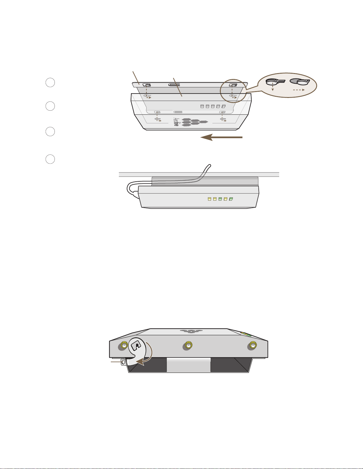
Figure 9 Attaching the HiveAP 340 to the Mounting Plate and Connecting Cables
With the HiveAP 340 upside
down, align its port side with
the bottom end of the plate.
Push the HiveAP 340 upward,
inserting the four tabs on the
plate into the four slots on the
HiveAP 340.
Slide the HiveAP 340 toward the
bottom end of the plate, locking
the tabs inside the slots.
Attach the antennas and connect the
cables to complete the installation.
4
6
7
5
Tab
inside
slot.
Tab
locked in
place.
Mounting Plate
HiveAP 340 (shown as transparent for clairty)
Tab
Slot
(side view)
Mounting Plate
HiveAP 340
Ceiling
Cables pass through the hole in
the mounting plate and ceiling
5 GHz (A)
5 GHz (B)5 GHz (C)
Rotate the
lock adapter
clockwise.
Insert a lock
through the
opening.
HiveAP 340
Mounting Plate
MOUNTING THE HIVEAP 340
When done, adjust the ceiling tiles back into their former position.
Locking the HiveAP 340
To lock the HiveAP 340 to the mounting plate, use either a Kensington lock or the lock adapter that is included with
the mounting kit and a small padlock (not included).
To use a Kensington lock, loop the cable attached to the lock around a secure object, insert th e T-bar component of
the lock into the device lock slot on the HiveAP, and then turn the key to engage the lock mechanism.
To use the lock adapter :
1. Insert the T-shaped extension on the adapter into the device lock slot, and rotate it clockwise so that the
2. Link a padlock through the opening in the adapter and engage the lock t o secure the HiveAP 340 to the
curved section extends through the slot in the mounting plate (see Figure 10).
Figure 10 Locking the HiveAP 340 to the Mounting Plate
mounting plate. The opening is 1/8" (0.3 cm) in diameter at its narrowest.
Deployment Guide 59
Page 40
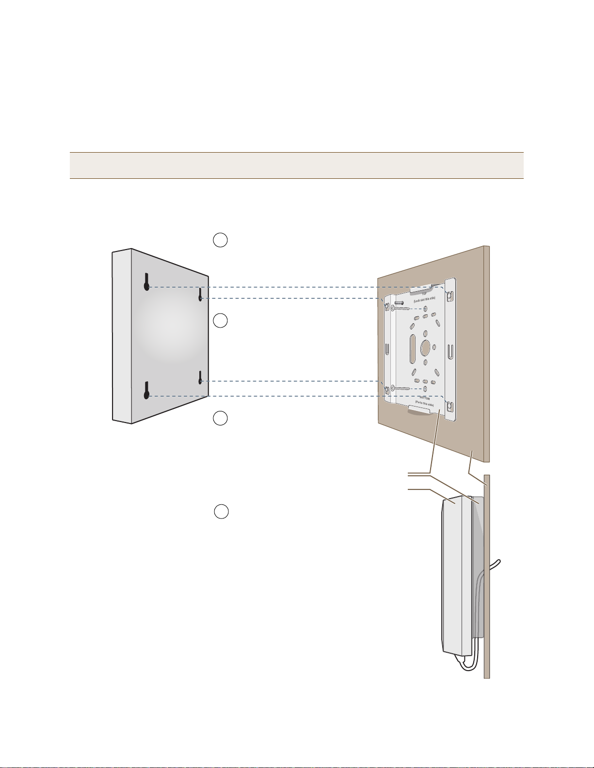
Chapter 4 The HiveAP 340 Platform
Mounting Plate
HiveAP 340
Wall
Insert the tabs on the mounting plate
into the slots on the underside of the
HiveAP 340. Then push the HiveAP
340 downward to lock it in place.
With the two wings at the sides of the plate
extending away from the surface, attach the
mounting plate to a secure object such as a
wall, ceiling, post, or beam.
1
3
Note: There are a variety of holes through which you can
screw or nail the plate in place. Choose the two or three
that best suit the object to which you are attaching it.
HiveAP 340
2
Cut or drill a hole through one of the
openings in the mounting plate to
pass the cables through to the
HiveAP 340.
Connect the cables to the HiveAP 340.
Depending on the deployment, you might
connect one or two Ethernet cables and a
power cable.
4
(side view)
Surface Mount
You can use the mounting plate to attach the HiveAP 340 to any surface that supports its weight, and to which you
can screw or nail the plate. First, mount the plate to the surface. Then, through one of the two large openings in
the plate, make a hole in the wall so that you can pass the cables through to the HiveAP.
Note: You can tie the cables to the tie points on the mounting plate to prevent them from being pulled out of
their connections accidentally.
Finally, attach the device to the plate, and connect the cables, as shown in Figure 11.
Figure 11 Mounting the HiveAP on a Wall
60 Aerohive
Page 41

DEVICE, POWER, AND ENVIRONMENTAL SPECIFICATIONS
DEVICE, POWER, AND ENVIRONMENTAL SPECIFICATIONS
Understanding the range of specifications for the HiveAP 340 is necessary for optimal deployment and device
operation. The following specifications describe the physical features and hardware components, the p ower adapter
and PoE (Power over Ethernet) electrical requirements, and the temperature and humidity ranges in which the
device can operate.
Device Specifications
• Chassis dimensions: 8 1/2" W x 1 1/4" H x 8" D (21.5 cm W x 3.2 cm H x 20.3 cm D)
• Weight: 3 lb. (1.36 kg)
• Antennas: Three omnidirectional 802.11b/g/n antennas, and th ree omnidirectional 802.11a/n antennas
• Serial port: RJ-45 (bits per second: 9600, data bits: 8, parity: none, stop bi ts: 1, flow control: none)
• Ethernet ports: autosensing 10/100/1000 Base-T/TX Mbps; both ports are compliant with the IEEE 802.3af
standard and the forthcoming 802.at standard for P oE (Power over Ethernet)
Power Specifications
• AC/DC power adapter:
• Input:100 – 240 VAC
• Output: 48V/0.38A
• PoE nominal input voltages:
• 802.3af: 48 V/0.35A
• Pre-802.3at: 48 V/0.625A
• RJ-45 power input pins: Wires 4, 5, 7, 8 or 1, 2, 3, 6
Environmental Specifications
• Operating temperature: -4 to 131 degrees F (-20 to 55 degrees C)
• Storage temperature: -40 to 176 degrees F (-40 to 80 degrees C)
• Relative Humidity: Maximum 95%
Deployment Guide 61
Page 42

Chapter 4 The HiveAP 340 Platform
62 Aerohive
Page 43

Chapter 5 The HiveAP 320 Platform
The Aerohive HiveAP 320 is a high-performance and highly reliable 802.11n wireless access point. The HiveAP 320
provides dual concurrent 802.11b/g/n and 802.11a/n radios for 3x3 MIMO (Multiple In, Multiple Out) and dual
10/100/1000 Ethernet ports for link aggregation or link redundancy. Its power management system uses a concept
called smart PoE (Power over Ethernet) to adjust its power consumption automatically in response the available
power in different environments. Smart PoE supports the IEEE 802.3af standard and the 802.3at pre-standard.
This chapter covers the following topics relating to the HiveAP 320:
• "HiveAP 320 Pro duct Overview" on page 64
• "Ethernet and Console Ports" on page 66
• "Status LEDs" on page 66
• "Antennas" on page 67
• "Mounting the HiveAP 320" on page 68
• "Ceiling Mount" on page 68
• "Surface Mount" on page 70
• "Device, Power, and Environmental Specifications" on page 71
Note: The HiveAP 320 supports all same 802.11n features as the HiveAP 340. Of particular interest is its support
of MIMO (Multiple Input, Multiple Output). For more information, see "MIMO" on page 55 and "Using MIMO
with Legacy Clients" on page 57.
Deployment Guide 63
Page 44

Chapter 5 The HiveAP 320 Platform
Device
Lock Slot
Reset
Button
Mounting
Plate
HIVEAP 320 PRODUCT OVERVIEW
The HiveAP 320 is a multi-channel wireless access point. It is compatible with IEEE 802.11b/g/n (2.4 GHz) and IEEE
802.11a/n (5 GHz) standards and supports a variety of Wi-Fi (wireless fidelity) security protocols, including WPA
(Wi-Fi Protected Access) and WPA2.
You can see the hardware components on the HiveAP in Figure 1. Each component is described in Table 1.
Figure 1 HiveAP 320 Hardware Components
ETH0
ETH1 48VDC CONSOLE
Status LEDs
POWER
WLAN0
WLAN1
ETH0
ETH1
Table 1 HiveAP 320 Component Descriptions
Component Description
Status LEDs The status LEDs convey operational states for system power, firmware,
Ethernet interfaces, and radios. For details, see "Status LEDs" on page 66.
ETH0 10/100/1000 Mbps PoE Port
and ETH1 10/100/1000 Mbps Port
The two 10/100/1000-Mbps Ethernet ports—ETH0 and ETH1—receive
RJ-45 connectors. The HiveAP can receive power through an Ethernet
connection to the ETH0 port from PSE (power sourcing equipment) that is
compatible with the 802.3af standard and the forthcoming 802.at
standard. Aerohive provides suitable PoE injectors as an optional
accessory. (If you connect the HiveAP to a power source through the
power connector and the ETH0 P oE port simultaneously, the device draws
power through the power connector and automatically disables PoE.)
64 Aerohive
Page 45

HIVEAP 320 PRODUCT OVERVIEW
Component Description
You can configure ETH0 and ETH1 as two individual Ethernet interfaces,
combine them into an aggregate interface to increase throughput, or
combine them into a redundant interface to increase reliability. You can
connect the HiveAP 320 to a wired network or to a wired device (such as
a security camera) through these ports using bridging. They are
compatible with 10/100/1000Base-T/TX and automatically negotiate
half- and full-duplex conn ections with the connecting device. They are
autosensing and adjust to straight-through and cross-over Ethernet cables
automatically. For details, see "Ethernet and Console Ports" on page 66.
48VDC
Power Connector
The 48-volt DC power connector (0.625 amps) is one of two methods
through which you can power the HiveAP 320. To connect it to a 100 –
240-volt AC power source, use the AC/DC power adaptor tha t is available
as an extra option. Because the HiveAP does not have an on/off switch,
connecting it to a power source automatically powers on the device.
Console Port You can access the CLI by making a serial connection to the RJ-45 console
port. The management station from which you make a serial connection
to the HiveAP must have a VT100 emulation program, such as Tera Term
©
(a free terminal emulator) or Hilgraeve Hyperterminal® (provided
Pro
with Windows® operating systems). The following are the serial
connection settings: bits per second: 9600, data bits: 8, parity: none,
stop bits: 1, flow control: none. For details, see "Ethernet and Console
Ports" on page 66.
Device Lock Slot You can physically secure the HiveAP by attaching it to a mounting plate
that is clipped to a ceiling track and then using a screw with a unique
head design to fasten the HiveAP to the mounting plate through the
device lock slot. The screw and special screw driver that fits the slot on
the screw head are included in the mounting kit. For more information,
see "Locking the HiveAP 320" on page 69.
Reset Button The reset button allows you to reboot the device or reset the HiveAP to
its factory default settings. Insert a paper clip , o r som et hing sim ilar, into
the Reset pinhole and press the reset button. To reboot the device, hold
the button down between 1 and 5 seconds. To return the configuration to
the factory default settings, hold it down for at least 5 seconds. After
releasing the button, the Power LED goes dark as the system reboots.
Then it pulses green while the firmware loads and the system performs a
self-test. After the software finishes loading, the Power LED glows steady
green.
To disable the reset button from resetting the configuration, enter this
command: no reset-button reset-config-enable Pressing the
button between 1 and 5 seconds will still reboot the Hive AP, but pressing
it for more than 5 seconds will not reset its configuration.
Note: The rear surface of the HiveAP 320 is used for heat dissipation to reduce the internal temperature.
Consequently, it can become hot, so use caution when handling it.
Deployment Guide 65
Page 46

Chapter 5 The HiveAP 320 Platform
Ethernet and Console Ports
There are three ports on the HiveAP 320: two RJ-45 10/100/1000Base-T/TX Ethernet ports and an RJ-45 console port.
The pin assignments in the PoE (Power over Ethernet) Ethernet ports follow the TIA/EIA-568-B standard (see
Figure 2 on page 50). The ports accept standard types of Ethernet cable—cat3, cat5, cat5e, or cat6. The ETH0 port
can receive power over the Ethernet cable from power sourcing equipment (PSE) that is 802.3af-compatible. If you
use cat5, cat5e, or cat6 cables, the ETH0 port can also support 802.3at-compliant PSE. Such equipment can be
embedded in a switch or router, or it can come from purpose-built devices that inject power into the Ethernet line
en route to the HiveAP. Because the PoE ports have autosensing capabilities, the wiring te rmin ation in the Ethe rnet
cable can be either straight-through or cross-over.
The HiveAP 320 supports the following features on its Ethernet ports:
• The HiveAP 320 supports smart PoE on its ETH0 port to adapt its power consumption to changes in the
amount of power available to it over Ethernet from PSE (power sourcing equipment). For more information,
see "Smart PoE" on page 51.
• The two Ethernet interfaces can be configured as aggregate interfaces for increased throughput and
redundant interfaces for increased reliability. For more information, see "Aggregate and Redundant
Interfaces" on page 51.
Through the RJ-45 console port, you can make a serial connection between your management system and the
HiveAP. The pin-to-signal mapping of the RJ-45 console port is the same as that for the HiveAP 340, which is shown
shown in Figure 3 on page 53. Similarly, cabling and connection details for the HiveAP 320 are same as those for the
HiveAP 340 (see Figure 4 on page 53).
Status LEDs
The five status LEDs on the top of the HiveAP 320 indicate various states of activity through their color (dark, green,
amber, and red) and illumination patterns (steady glow or pulsing). The meanings of the various color + illumination
patterns for each LED are explained below.
Power
•Dark: No power
• Steady green: Powered on and the firmware is running normally
• Pulsing green: Firmware is booting up
• Steady amber: Firmware is being updated
• Pulsing amber: Alarm indicating a firmware issue has occurred
• Steady red: Alarm indicating a hardware issue has occurred
ETH0 and ETH1
• Dark: Ethernet link is down or disabled
• Steady green: 1000 Mbps Ethernet link is up but inactive
• Pulsing green: 1000 Mbps Ethernet link is up and active
• Steady amber: 10/100 Mbps Ethernet link is up but inactive
• Pulsing amber: 10/100 Mbps Ethernet link is up and active
WIFI0 and WIFI1
• Dark: Wireless interface is disabled
• Steady green: Wireless interface is in access mode but inactive
• Pulsing green: Wireless interface is in access mode and active
• Steady amber: Wireless interface is in backhaul mode but inactive
• Pulsing amber: Wireless interface is in backha ul mode and is connected with other hive members
• Alternating green and amber: Wireless interface is in backhaul mode and is searching for other hive
members
66 Aerohive
Page 47

HIVEAP 320 PRODUCT OVERVIEW
R
RF 8
o
5 GH
.4 GHz
Cut-away view of the HiveAP 320 to show the relationship of the antennas and the two internal radios
Antennas
Antennas are an integral part of the HiveAP 320. The HiveAP 320 has six internal s ingle-band antenna s. Three of the
antennas operate in the 2.4-GHz band (IEEE 802.11b/g/n) and have a 2-dBi gain. The other three antennas operate
in the 5-GHz band (IEEE 802.11a/n) and have a 3-dBi gain. All antennas are omnidirectional, providing fairly equal
coverage in all directions in a toroidal (donut-shaped) pattern around each antenna (see Figure 4 on page 30).
The three three 2.4-GHz antennas link to radio 1, and the three 5-GHz antennas link to radio 2. Conceptually, the
relationship of antennas and radios is shown in Figure 2.
Figure 2 Antennas and Radios
2.4 GHz
Antennas
Radio 1
RF 802.11b/g/n
1
2.4 GHz
Radio 2
RF 802.11a/n
5 GHz
5 GHz
Antennas
The wifi0 interface links to radio 1 (frequency range = 2.4 GHz for IEEE 802.11b/g), and the wifi1 interface links to
radio
2 (frequency range = 5 GHz for IEEE 802.11a). These interface-to-radio relationships are permanent.
Although hive members automatically adjust their signal strength according to their environments, you can resize
the area of coverage by increasing or decreasing the signal strength manually by entering the interface {
wifi0 | wifi1 } radio power <number> command, where <number> can be from 1 to 20 and represents
a value in dBm.
Deployment Guide 67
Page 48
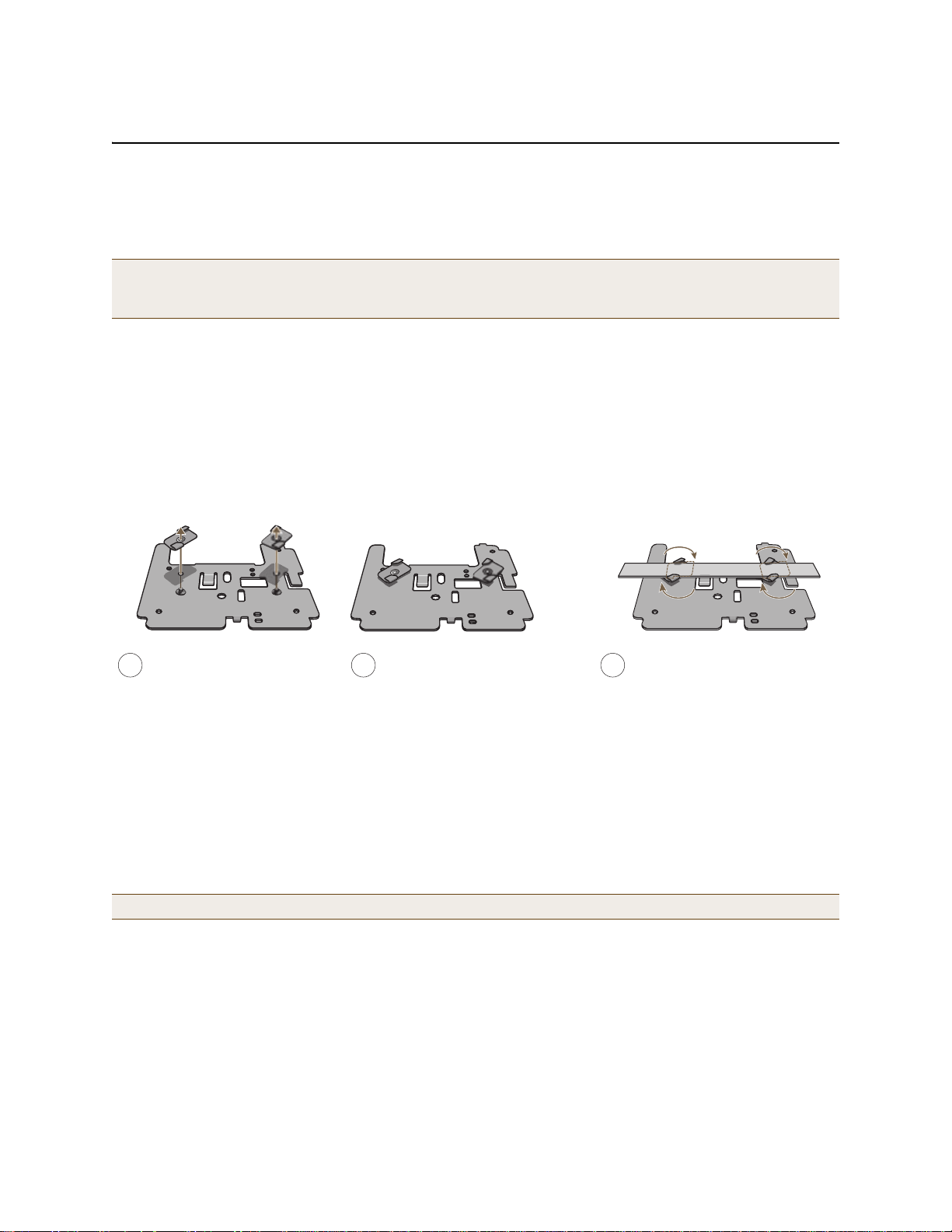
Chapter 5 The HiveAP 320 Platform
Ceiling Track
Track Clips
Mounting Plate
3
1
Press the clips against the ceiling
track and swivel them until they
snap into place, gripping the edges
of the track.
If necessary, slide the clips and
mounting plate along the track until
they are in the spot you want.
Insert the screws through the
mounting plate and thread them
into the track clips, fastening
the clips firmly to the plate.
2
Adjust the track clips so that
their tabs can pass on either
side of a ceiling track.
MOUNTING THE HIVEAP 320
Using the mounting plate and track clips, you can mount the HiveAP 320 to the tracks of a dropped ceiling grid.
Using just the mounting plate, you can mount the HiveAP to any surface that can support its weight (2 lb., 0.68 kg).
Note: In addition to these methods, you can also mount the HiveAP 320 on a table using the set of four rubber
feet that ship with the product. Simply peel the rubber feet off the adhesive sheet and press them against
the underside of the HiveAP in its four corners.
Ceiling Mount
To mount the HiveAP 320 to a track in a dropped ceiling, you need the mounting plate, two track clips, and two K eps
nuts. all of which ship as an option with the HiveAP 320. You also need a drill and—most likely—a ladder.
Nudge the ceiling tiles slightly away from the track to clear some space. Fasten the track clips to the mounting
plate, and then attach them to the ceiling track, as shown in Figure 3.
Figure 3 Attaching the Track Clips and Mounting Plate to the Ceiling Track
When you have the mounting plate in the correct location, cut or drill a hole in the ceiling through which you can
then pass the Ethernet and power cables. Pa ss the cables through the hole and attach them to the HiveAP 320,
leaving some slack so that you can easily maneuver the HiveAP into place, attaching it to the mounting plate as
shown in Figure 4 on page 69.
Note: For clarity, the power and Ethernet cables are not shown in the illustrations.
68 Aerohive
Page 49
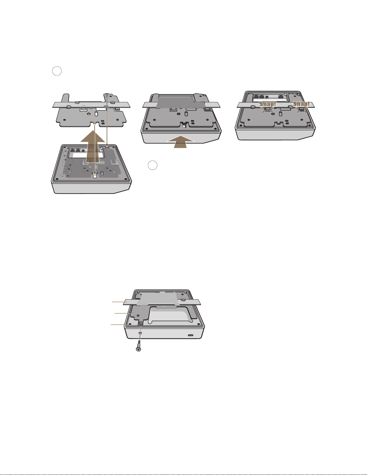
Figure 4 Attaching the HiveAP 320 to the Mounting Plate
HiveAP 320
Mounting Plate
Ceiling Track Note: The ceiling tiles are removed for clarity.
With the HiveAP 320 upside down, align the round tab and security screw
4
hole extnesion on the mounting plate with the keyhole opening and security
screw cavity on the HiveAP 320, and press the HiveAP upward.
Push HiveAP
Pushing from the LED end of the HiveAP, slide it toward the bottom
5
end of the plate until the two rippled tabs on the mounting plate
snap over the nubs on the undersdie of the HiveAP.
MOUNTING THE HIVEAP 320
When done, adjust the ceiling tiles back into their former position.
Locking the HiveAP 320
To lock the HiveAP 320 to the mounting plate, use the security screw and bit that are included with the mounting
kit. You will also need a screw driver or an electric drill that will accept the bit.
1. Insert the security screw through the hole in the HiveAP 320 and begin to threa d it into the ho le in the mou nting
plate (see Figure 5).
Figure 5 Locking the HiveAP 320 to the Mounting Plate
Security Screw
2. With the security screw bit in a screw driver or electric drill, tighte n the screw into place, securing the HiveAP
to the mounting plate.
Deployment Guide 69
Page 50
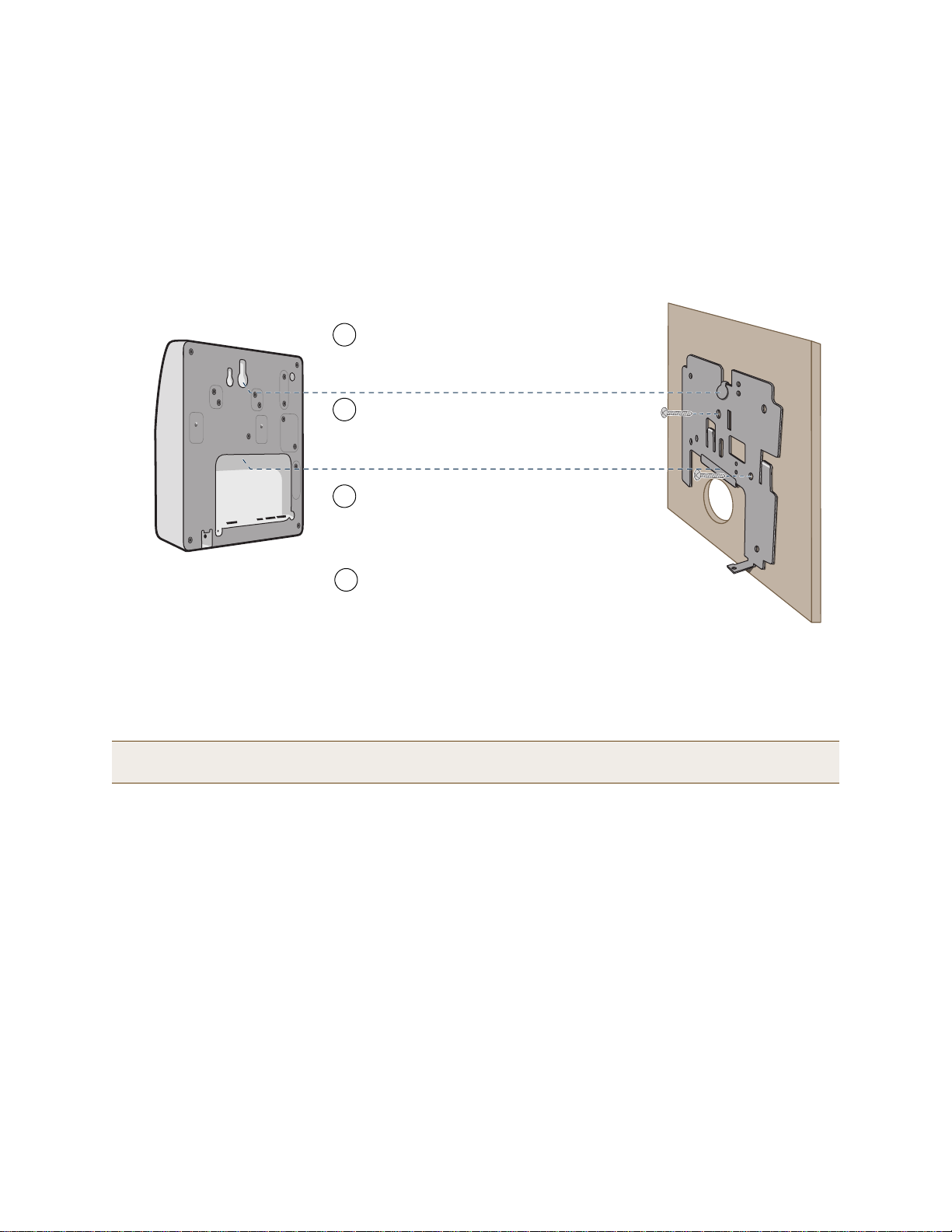
Chapter 5 The HiveAP 320 Platform
Insert the tabs on the mounting plate into the
slots on the underside of the HiveAP 320.
Then push the HiveAP 320 downward to
lock it in place.
Orient the mounting plate as shown and attach
it to a secure object such as a wall, ceiling,
post, or beam.
1
3
Note: There are a variety of holes through which you can screw or nail the plate in
place. Choose the two or three that best suit the object to which you are attaching it.
HiveAP 320
2
Cut or drill a hole through the large space
near the bottom of the mounting plate to
pass the cables through to the HiveAP 320.
Connect the cables to the HiveAP 320.
Depending on the deployment, you might connect
one or two Ethernet cables and a power cable.
4
(side view)
wall
Mounting
Plate
Surface Mount
You can use the mounting plate to attach the HiveAP 320 to any surface that supports its weight, and to which you
can screw or nail the plate. First, mount the plate to the surface. Then, through the large opening in the lower p art
of the plate, make a hole in the wall so that you can pass the cables through to the HiveAP.
Finally, attach the device to the plate, and connect the cables, as shown in Figure 6.
Figure 6 Mounting the HiveAP 320 on a Wall
Note: You can use the locking screw to secure the HiveAP 320 to the mounting plate. For information, see
"Locking the HiveAP 320" on page 69.
70 Aerohive
Page 51

DEVICE, POWER, AND ENVIRONMENTAL SPECIFICATIONS
DEVICE, POWER, AND ENVIRONMENTAL SPECIFICATIONS
Understanding the range of specifications for the HiveAP 320 is necessary for optimal deployment and device
operation. The following specifications describe the physical features and hardware components, the p ower adapter
and PoE (Power over Ethernet) electrical requirements, and the temperature and humidity ranges in which the
device can operate.
Device Specifications
• Chassis dimensions: 7 7/8" W x 1 1/2" H x 7 7/8" D (20 cm W x 3.8 cm H x 20 cm D)
• Weight: 2 lb. (0.68 kg)
• Antennas: Three omnidirectional 802.11b/g/n antennas, and th ree omnidirectional 802.11a/n antennas
• Serial port: RJ-45 (bits per second: 9600, data bits: 8, parity: none, stop bi ts: 1, flow control: none)
• Ethernet ports: two autosensing 10/100/1000 Base-T/TX Mbps ports; the ETH0 port is compliant with the IEEE
802.3af standard and the forthcoming 802.at standard for PoE (Power over Ethernet)
Power Specifications
• AC/DC power adapter:
• Input:100 – 240 VAC
• Output: 48V/0.38A
• PoE nominal input voltages:
• 802.3af: 48 V/0.35A
• Pre-802.3at: 48 V/0.625A
• RJ-45 power input pins: Wires 4, 5, 7, 8 or 1, 2, 3, 6
Environmental Specifications
• Operating temperature: 32 to 104 degrees F (0 to 40 degrees C)
• Storage temperature: -4 to 158 degrees F (-20 to 70 degrees C)
• Relative Humidity: Maximum 95%
Deployment Guide 71
Page 52

Chapter 5 The HiveAP 320 Platform
72 Aerohive
Page 53

Chapter 10 HiveOS
Hive Members
Wired or Wireless Hive Communications (Backhaul)
Wireless Network Access Connections
Wired Ethernet Network Connections
Not shown: Switches for wired backhaul
connections and the portal link to the wired network.
Wireless Clients
Wireless Clients
Wireless Clients
Hive
You can deploy a single HiveAP and it will provide wireless access as an autonomous AP (access point). However, if
you deploy two or more HiveAPs in a hive, you can provide superior wireless access with many benefits. A hive is a
set of HiveAPs that exchange information with each other to form a collaborative whole (see Figure 1). Through
coordinated actions based on shared information, hive members can provide the following services that autonomous
APs cannot:
• Consistent QoS (quality of service) policy enforcement across all hive members
• Coordinated and predictive wireless access control that provides fast roaming to clients moving from one hive
member to another
• Best-path routing for optimized data forwarding
• Automatic radio frequency and power selection
Figure 1 HiveAPs in a Hive
Deployment Guide 153
Page 54

Chapter 10 HiveOS
COMMON DEFAULT SETTINGS AND COMMANDS
Many major components of HiveOS are automated and typically require no further configuration. For example, radio
power and frequency selection occurs automatically, as does route learning. Also, after defining a hive and its
security protocol suite, all HiveAPs belonging to that hive automatically initiate and maintain communications with
each other.
Additionally, there are many default settings that simplify the setup of a HiveAP because these are the typical
settings for many of the most common deployments. The following are some important default settings and the
commands necessary to change them if you need to do so:
Default Settings Commands
mgt0 interface DHCP client = enabled To disable the DHCP client:
no interface mgt0 dhcp client
To set an IP address:
interface mgt0 ip ip_addr netmask
VLAN ID = 1 To set a different VLAN ID:
interface mgt0 vlan number
wifi0 and wifi1
interfaces
Default QoS policy def-user-qos policy:
User profile default-profile:
wifi0 mode = access
wifi1 mode = backhaul
wifi0 radio profile = radio_g0
wifi1 radio profile = radio_a0
antenna = internal To have the wifi0 interface use an external antenna:
channel = automatic selection To set a specific radio channel:
power = automatic selection To set a specific transmission power level (in dBms):
user profile rate = 54,000 Kbps
user profile weight = 10
user rate limit = 54,000 Kbps
mode = weighted round robin for
Aerohive classes 0 - 5; strict
forwarding for classes 6 - 7
classes 0 - 4 rate limit = 54,000 Kbps
class 5 rate limit = 10,000 Kbps
classes 6 - 7 rate limit = 512 Kbps
group ID = 0
policy name = def-user-qos
VLAN ID = 1
To change the mode of the wifi0 or wifi1 interface:
interface { wifi0 | wifi1 } mode { access
| backhaul }
To change the radio profile of the wifi0 or wifi1
interface to a different, previously defined profile:
interface { wifi0 | wifi1 } radio profile
string
interface { wifi0 | wifi1 } radio antenna
external
interface { wifi0 | wifi1 } radio channel
number
interface { wifi0 | wifi1 } radio power
number
To change the default QoS policy:
qos policy def-user-qos qos ah_class
{ strict rate_li
rate_limit weight }
qos policy def-user-policy user-profile
rate_limit weight
qos policy def-user-policy user
rate_limit
You cannot change the group ID or QoS policy name
for the default user profile. To change its VLAN ID:
user-profile default-profile vlan-id
number
mit 0 | wrr
154 Aerohive
Page 55

CONFIGURATION OVERVIEW
CONFIGURATION OVERVIEW
The amount of configuration depends on the complexity of your deployment. As you can see in "Deployment
Examples (CLI)" on page 161, you can enter a minimum of three commands to deploy a single HiveAP, and just a few
more to deploy a hive.
However, for cases when you need to fine tune access control for more complex environments, HiveOS offers a rich
set of CLI commands. The configuration of HiveAPs falls into two main areas: "Device-Level Configurations" and
"Policy-Level Configurations" on page 156. Consider your deployment plans and then refer to the following sections
for guidance on the commands you need to configure them.
Note: To find all commands using a particular character or string of characters, you can do a search using the
following command: show cmds | { include | exclude } string
Device-Level Configurations
Device-level configurations refer to the management of a HiveAP and its connectivity to wireless clients, the wired
network, and other hive members. The following list contains some key areas of device-level configurations and
relevant commands.
• Management
• Administrators, admin authentication method, login parameters, and admin privileges
admin { auth | manager-ip | min-password-length | read-only | read-write |
root-admin } …
• Logging settings
log { buffered | console | debug | facility | flash | server | trap } …
• Connectivity settings
•Interfaces
interface { eth0 | wifi0 | wifi1 } …
• Layer 2 and layer 3 forwarding routes
route mac_addr …
ip route { default | host | net } ip_addr …
• VLAN assignments
For users:
user-profile string qos-policy string vlan-id number attribute number
For hive communications:
hive string native-vlan number
For the mgt0 interface:
interface mgt0 vlan number
• Radio settings
radio profile string …
Deployment Guide 155
Page 56
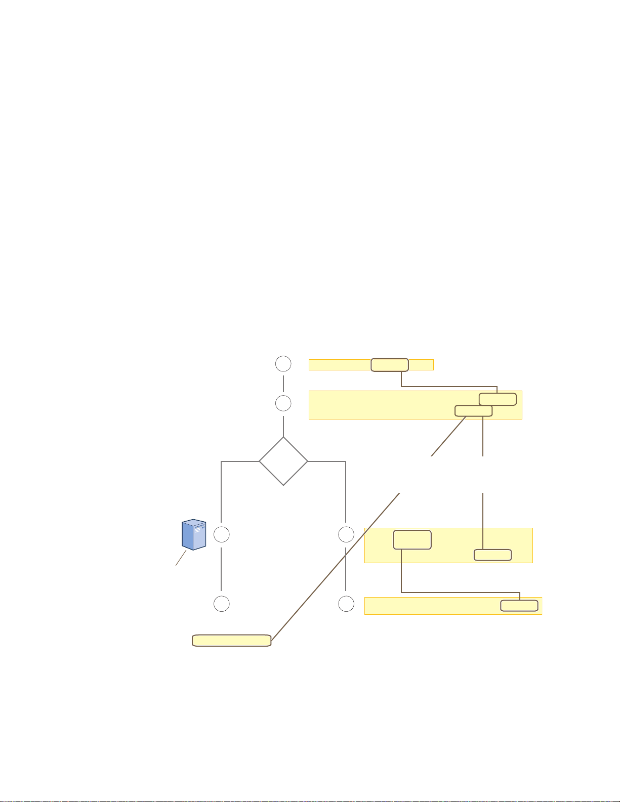
Chapter 10 HiveOS
user-profile string qos-policy string
vlan-id number attribute number
2
3
1
44
User accounts are stored
on the RADIUS Server.
Returned Attributes
• Tunnel Type = GRE (value = 10)
• Tunnel Medium Type = IPv4 (value = 1)
• Tunnel Private Group ID = user_profile_number
First, configure a QoS policy that you want to apply
to wireless traffic from a group of users.
The HiveAP applies the QoS policy to all
wireless clients that associate with the SSID.
ssid string
ssid string default-
user-profile-attr number
3
The attributes indicate which user profile to apply to the user,
and the profile in turn indicates which QoS policy to apply.
If you use a RADIUS server, configure
it to return attributes for the realm to
which the wireless users belong. After
authenticating a user, the server
returns these attributes with the
Access-Accept message. The
attributes indicate which
user profile to apply to the
user, and the profile in turn
indicates the QoS policy to
apply.
qos policy string ...
interface interface ssid string
Second, configure a user profile that references the
QoS policy you just configured.
Assign the SSID to an interface.
RADIUS
Server?
NoYes
The next step depends on whether you use
a RADIUS server to authenticate users.
If you do not use a RADIUS server, create
an SSID that specifies the user profile
attr bute as its default user profile.
Policy-Level Configurations
Policies control how wireless clients access the network. The following list contains some key areas of policy-level
configurations and relevant commands.
•QoS settings
qos { classifier-map | classifier-profile | marker-map | marker-profile |
policy } …
•User profiles
user-profile string …
• SSIDs
ssid string …
• AAA (authentication, authorization, and accounting) settings for IEEE 802.1X authentication
aaa radius-server …
While the configuration of most HiveOS features involves one or more related commands, to define and apply a QoS
policy to a group of users, you must configure several different but related features: a QoS policy, a user profile,
and—if you do not authenticate users with a RADIUS server—an SSID that references the user profile, and a
subinterface to which you assign the SSID. The configuration steps are shown in Figure 2.
Figure 2 Steps for Configuring and Applying QoS
156 Aerohive
Page 57

HIVEOS CONFIGURATION FILE TYPES
(Note: The commands in o bold have not yet been saved,
which is why they do not appear in the current config.)
Current Config
(in flash memory)
Running Config
(in DRAM)
The running config comprises the current config
plus any commands that have not yet been
saved. The running config runs in DRAM.
The current config comprises saved
commands plus default settings. The
current config is stored in flash memory.
Running Config New Current Config
Previous Current Config
(overwritten)
When you enter the a e co fig save config command,
the HiveAP
saves the running config from
DRAM to flash memory
, where it becomes
the new current config, replacing the one
previously there.
save config
(Note: After entering the a e save
onfigconfig command, the current and
running configs become identical.)
HIVEOS CONFIGURATION FILE TYPES
HiveOS supports several types of configuration files: running, current, backup, bootstrap, default, and failed.
The running configuration (config) is the configuration that is actively running in DRAM. During the bootup process,
a HiveAP loads the running config from one of up to four config files stored in flash memory:
• current: a flash file containing a combination of default and admin-defined settings. During the bootup process,
this is the first config that the HiveAP attempts to load as the running config. This is also the file to which you
typically save commands from the running config (you can also save them to the bootstrap config). See Figure 3.
• backup: a flash file that the HiveAP attempts to load during the reboot process if there is a newly uploaded
current config file or if it cannot load the current config file. See Figure 4 on page 158 and Figure 5 on
page 158.
• bootstrap: a flash file containing a second config composed of a combination of default and admin-defined
settings. The HiveAP fails over to this config when you enter the reset config command or if both the
current and backup config files fail to load. See Figure 6 on page 160.
• default: a flash file containing only default settings. If there is no bootstrap config, the HiveAP reverts to this
config when you enter the reset config command or if both the current and backup config files fail to load.
See Figure 6 on page 160.
Note: There is also a failed config file, which holds any backup config that fails to load. See Figure 5 on
page 158.
When using the CLI, the two most frequently accessed config types are the running config and current config. When
you enter a command in the running config, the HiveAP performs it immedia tely. However, because the running
config is stored in volatile memory (DRAM), the commands are not yet permanent and will be lost when the HiveAP
next reboots. For your configuration settings to persist after rebooting, enter the save config command. This
command saves the running config to the current config, which is a file stored in nonvolatile (flash) memory. See
Figure 3.
Figure 3 Relationship between Running and Current Config Files
Deployment Guide 157
Page 58
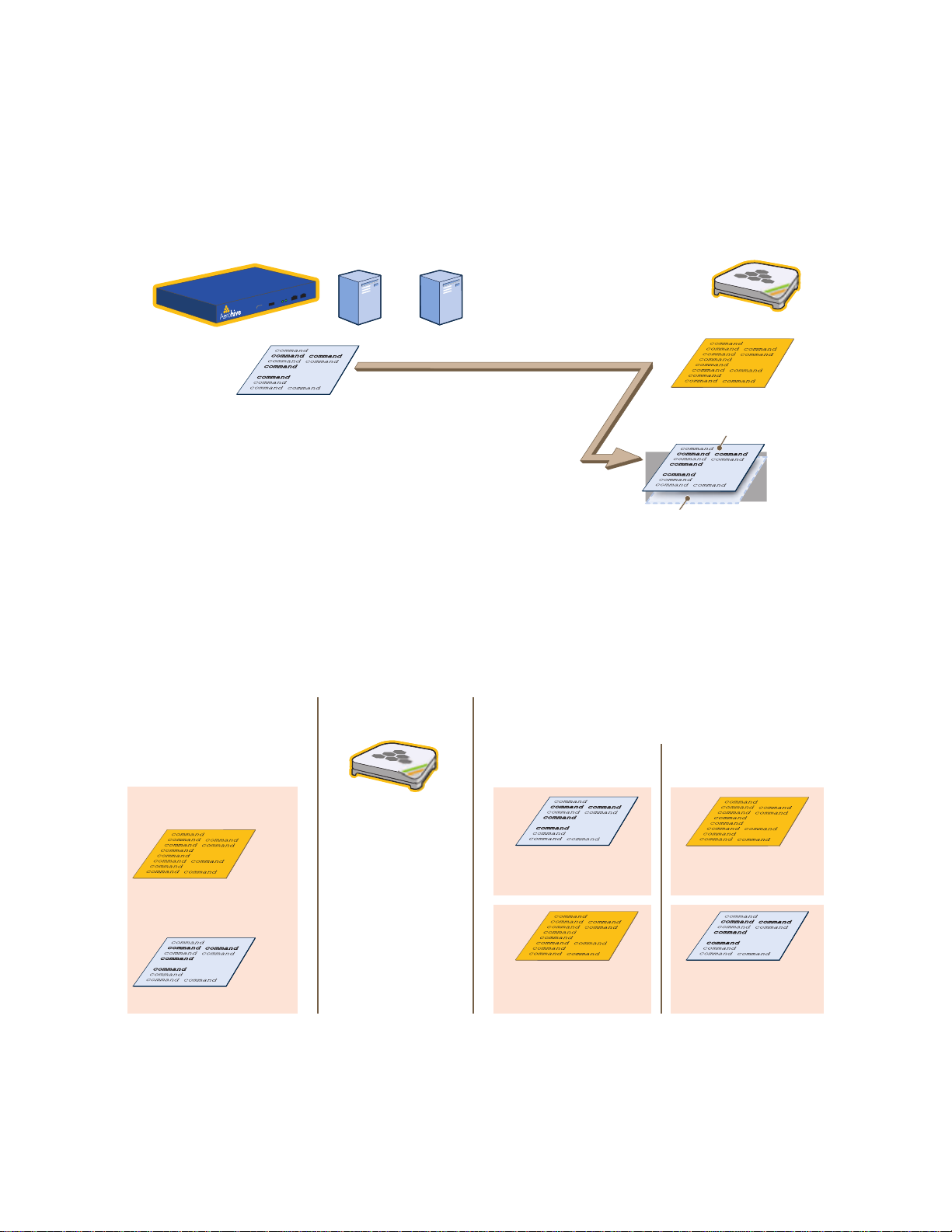
Chapter 10 HiveOS
Current Config
(existing config)
Backup Config
(newly uploaded config file)
After uploading a new config
file, the following two config
files are stored in flash
memory on the HiveAP:
When you reboot the HiveAP, it tries to load the backup
config. Either of the following two results can occur:
If the newly loaded config
file loads successfully, . . .
. . . it becomes the new
current config, and . . .
. . . the previous current
config becomes the new
backup config.
. . . the backup config is
saved as a failed config
(for diagnostic analysis).
. . . the HiveAP reboots
again, loads the previous
current config, and . . .
If the newly loaded config
file fails to load, . . .
Reboot the HiveAP
When you upload a configuration file from HiveManager or from a TFTP or SCP server, the HiveAP stores the
uploaded file in the backup config partition in flash memory , where it remains until the Hive AP reboots. If there is a
backup config file already stored in flash, the newly uploaded file overwrites it. See Figure 4.
Figure 4 Relationship between Current and Backup Config Files during a File Upload
HiveManager or or HiveAP
Config File
When you upload a config file from HiveManager or a TFTP or
SCP server, the HiveAP saves the uploaded file as a backup
config. This file replaces any previous backup config file that
might have been there.
TFTP
Server
SCP
Server
Current Config
New Backup Config
(in flash memory)
Previous Backup Config
(overwritten)
When the HiveAP reboots, it attempts to load the the newly uploaded config file. If the file loads successfully, the
HiveAP makes that file the new current config and makes the previous current config the new backup config. If the
file does not load successfully, the HiveAP reboots again and loads the previous current config file. The HiveAP saves
the file it was unable to load as a failed config for diagnostics. See Figure 5.
Figure 5 Relationship between Current and Backup Config Files while Rebooting a HiveAP
158 Aerohive
Page 59

HIVEOS CONFIGURATION FILE TYPES
Note: To upload and activate a config file from HiveManager , see "Uploading HiveAP Configurations" on
page 150. To upload and activate a config file from a TFTP or SCP server using the CLI, use the following
commands:
save config tftp://ip_addr:filename current { hh:mm:ss | now | offset hh:mm:ss }
save config scp://username@ip_addr:filename current { hh:mm:ss | now | offset
hh:mm:ss }
When a HiveAP ships from the factory, it is loaded with a default config file, which acts initially as the running and
current configs. If you enter and save any commands, the HiveAP then stores a separate config file as the current
config, combining the default settings with the commands you entered and saved. If you want to return to the
default settings, you can press the reset button (see "Reset Button" on page 27) or enter the reset config
command. A HiveAP might also return to the default config if both the current and backup configs fail to load,
which might happen if you update the HiveOS firmware to an image that cannot work with either config.
Note: You can disable the ability of the reset button to reset the configuration by entering this command: no
reset-button reset-config-enable
Reverting to the default config can be very useful, especially in the early stages when you are still learning about
HiveOS and are likely to be experimenting with different settings. However, retaining the ability of a HiveAP to
revert to its default settings after its deployment can present a problem if it is a mesh point in a hive. If the HiveAP
reverts to the default config, it will not be able to rejoin its hive. Consequently, it will not be able to get an IP
address through DHCP nor be able to communicate with HiveManager (assuming that you are managing it through
HiveManager). In this case, you would have to make a serial connection to the console port on the HiveAP and
reconfigure its hive settings through the CLI.
To avoid the above situation, you can use a bootstrap config. A bootstrap config is typically a small config file that
comes last in the boot or der (current – backup – bootstrap) and that replaces the default config as the one a HiveAP
loads when you reset the configuration. See Figure 6 on page 160.
Note: Be careful to remember the login name and password defined in the bootstrap config file. If they become
lost or forgotten, you must obtain a one-time login key from Aerohive technical support. To get the key,
you must already have had a support contract in place. The first one-time login key is free. After that,
there is a small handling fee for each additional key.
Deployment Guide 159
Page 60

Chapter 10 HiveOS
When you enter the reset fig reset config command or press the
reset button on the front panel of the HiveAP device, the
HiveAP deletes the previous current config, reboots, and
loads the bootstrap config— if present—or the default config.
reset config
Current Config
Bootstrap Config
Default Config
. . . or if there is no bootstrap config . . .
Resetting the Configuration
Current Config
Backup Config Bootstrap Config
Default Config
. . . or if there is no bootstrap config . . .
If the HiveAP cannot load either the current or backup
config files, it deletes them, reboots, and loads the
bootstrap config— if present—or the default config.
Configuration Failover Behavior
Failover Failover
Figure 6 Relationship of Current, Backup, Bootstrap, and Default Config Files
To create and load a bootstrap config, make a text file containing a set of commands that you want the HiveAP to
load as its bootstrap configuration (for an example, see "Loading a Bootstrap Configuration" on page 179). Save the
file locally and then load it with one of the following commands:
save config tftp://ip_addr:filename bootstrap
save config scp://username@ip_addr:filename bootstrap
Note: Similar to the way that a current config consists of the commands you added on top of the default config,
a bootstrap config consists of default definitions and settin gs plus whatever other settings you configure.
After it is loaded, you can enter the following command to view the bootstrap file: show config bootstrap
If you want to run the bootstrap config, enter the following commands:
load config bootstrap
reboot
When the bootstrap config loads, enter the login parameters you defined for that configuration. To return to your
previous current config file, enter the following commands:
load config backup
reboot
160 Aerohive
Page 61

Chapter 11 Deployment Examples (CLI)
This chapter presents several deployment examples to introduce the primary tasks involved in configuring HiveAPs
through the HiveOS CLI.
In "Deploying a Single HiveAP" on page 162, you deploy one HiveAP as an autonomous access point. This is the
simplest configuration: you only need to enter and save three commands.
In "Deploying a Hive" on page 165, you add two more HiveAPs to the one deployed in the first example to form a hive
with three members. The user authentication method in this and the previous example is very simple: a preshared
key is defined and stored locally on each HiveAP and on each wireless client.
In "Using IEEE 802.1X Authentication" on page 170, you change the user authentication method. Taking advantage of
existing Microsoft AD (Active Directory) user accounts, the HiveAPs use IEEE 802.1X EAP (Extensible Authentication
Protocol) to forward authentication requests to a RADIUS server whose database is linked to that of the AD server.
In "Applying QoS" on page 173, you apply QoS (Quality of Service) filters to user traffic so that delay-sensitive voice
traffic receives higher pr iority than other more delay-resistant traffic.
Note: To focus attention on the key concepts of an SSID (first example), hive (second example), and IEEE 802.1X
authentication (third example), QoS was intentionally omitted from these examples. However, the QoS
settings you define in the last example can apply equally well to the configurations in the others.
In "Loading a Bootstrap Configuration" on page 179, you load a bootstrap config file on the HiveAPs. When a
bootstrap config is present, it loads instead of the default config whenever HiveOS is reset or if the current and
backup configs do not load. This example shows how using a bootstrap config can help minimize theft and increase
convenience.
Because each example builds on the previous one, it is recommended to read them sequentially. Doing so will help
build an understanding of the fundamentals involved in configuring HiveAPs.
If you want to view just the CLI commands used in the examples, see "CLI Commands for Examples" on page 182.
Having the commands in blocks by themselves makes it easy to copy-and-paste them at the command prompt.
The following are the equipment and network requirements for these examples:
•Equipment
• Management system (computer) capable of creating a serial connection to the HiveAP
• VT100 emulator on the management system
• Serial cable (also called a "null modem cable") that ships as an option with the HiveAP product. You use this
to connect your management system to the HiveAP.
Note: You can also access the CLI by using Telnet or SSH (Secure Shell). After connecting a HiveAP to the
network, make either a Telnet or SSH connection to the IP address that the DHCP server assigns the
mgt0 interface.
•Network
• Layer 2 switch through which you connect the HiveAP to the wired network
• Ethernet cable—either straight-through or cross-over
• Network access to a DHCP server
• For the third and fourth examples, network access to an AD (Active Directory) server and RADIUS server
Deployment Guide 161
Page 62
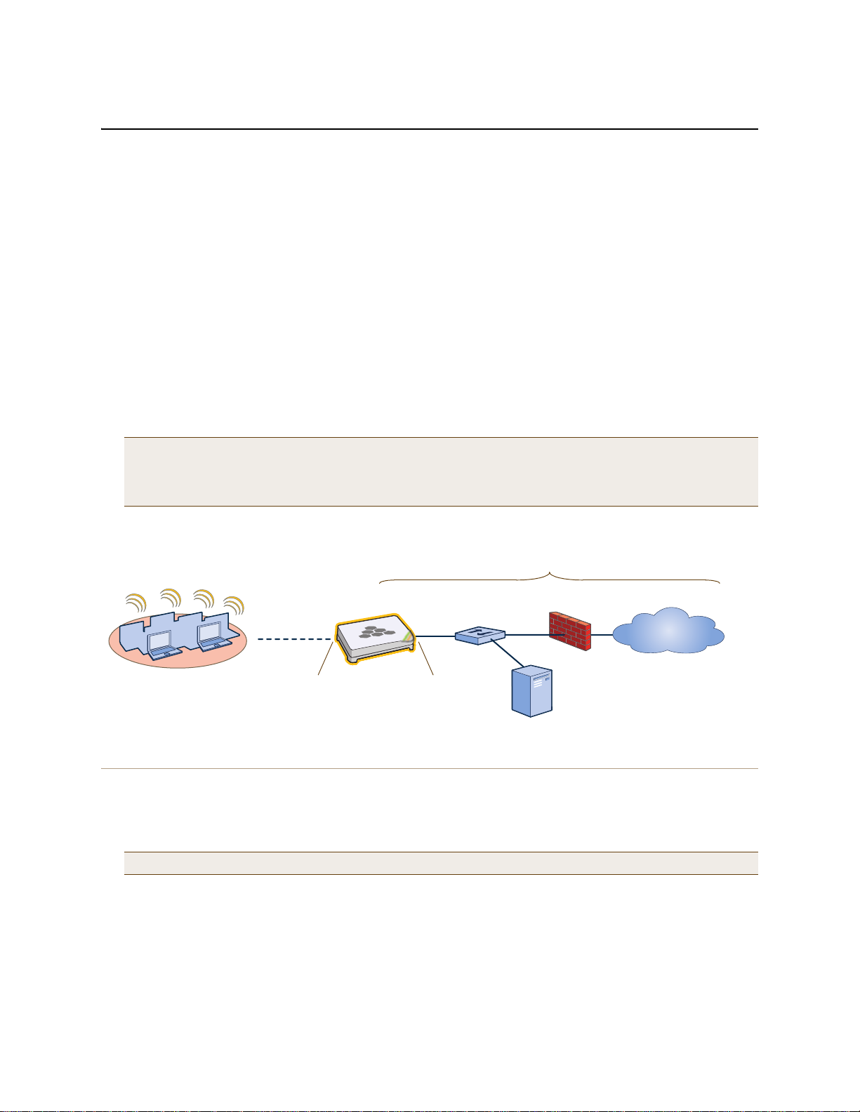
Chapter 11 Deployment Examples (CLI)
Wireless Network-1
HiveAP-1 Switch Firewall
Internet
DHCP Server
Wireless clients associate
with HiveAP-1 using SSID
"employee" with the security
suite WPA-auto-psk
(PSK = N38bu7Adr0n3).
The wireless clients and the mgt0
interface on HiveAP-1 receive their
IP addresses and associated TCP/IP
settings from the DHCP server.
Wired Network
wifi0 interface
SSID "employee"
Access mode
IEEE 802.11b/g/n
Physical interface: eth0
Logical interface: mgt0
Backhaul mode
Network portal
EXAMPLE 1: DEPLOYING A SINGLE HIVEAP
In this example, you deploy one HiveAP (HiveAP-1) to provide network access to a small offi ce w ith 15 – 2 0 wi re less
clients. You only need to define the following SSID (service set identifier) parameters on the HiveAP and clients:
• SSID name: employee
• Security protocol suite: WPA-auto-psk
• WPA – Uses Wi-Fi Protected Access, which provides dynamic key encryption and mutual authentication of
the client and HiveAP
• Auto – Automatically negotiates WPA or WPA2 and the encryption protocol: AES (Advanced Encryption
Standard) or TKIP (Temporal Key Integrity Protocol)
• PSK – Derives encryption keys from a preshared key that the client and HiveAP both already have
• Preshared key: N38bu7Adr0n3
After defining SSID "employee" on HiveAP-1, you then bind it to the wifi0 interface, which is in access mode by
default. The wifi0 interface operates at 2.4 GHz (in accordance with the IEEE 802.11b, g, and n standards). This
example assumes that the clients also support 802.11b, g, or n.
Note: By default, the wifi1 interface is in backhaul mode and operates at 5 GHz to support IEEE 802.11a. To
put wifi1 in access mode so that both interfaces provide access—the wifi0 interface at 2.4 GHz and the
wifi1 interface at 5 GHz—enter this command: interface wifi1 mode access. Then, in addition
to binding SSID "employee" to wifi0 (as explained in step 2), also bind it to wifi1.
Figure 1 Single HiveAP for a Small Wireless Network
Step 1 Log in through the console port
1. Connect the power cable from the DC power connector on the HiveAP to the AC/DC power adaptor that ships
with the device as an option, and connect that to a 100 – 240-volt power source.
The Power LED glows steady amber during the bootup process. After the bootup process completes, it then
glows steady green to indicate that the firmware is loaded and running.
2. Connect one end of an RS-232 serial (or "null modem") cable to the serial port (or Com port) on your
management system.
3. Connect the other end of the cable to the male DB-9 or RJ-45 console port on the HiveAP.
Note: If the switch supports PoE (Power over Ethernet), the HiveAP can receive its power that way instead.
162 Aerohive
Page 63

EXAMPLE 1: DEPLOYING A SINGLE HIVEAP
4. On your management system, run a VT100 terminal emulation program, such as Tera Term Pro© (a free terminal
emulator) or Hilgraeve Hyperterminal® (provided with Windows® operating systems). Use the following settings:
• Bits per second (baud rate): 9600
• Data bits: 8
• Parity: none
•Stop bits: 1
• Flow control: none
For HiveAPs set with "FCC" as the region code, the Initial CLI Configuration W izard appears. For HiveAPs set with
"world" as the region code, a prompt appears to set the country code for the location where you intend to
deploy the HiveAP. To set the country code, enter the boot-param country-code number command, in
which number is the appropriate country code number. For a list of country codes, see "Appendix A Country
Codes" on page 189.
5. Because you do not need to configure all the settings presented in the wizard, press N to cancel it.
The login prompt appears.
6. Log in using the default user name admin and password aerohive.
Step 2 Configure the HiveAP
1. Create an SSID and assign it to an interface.
ssid employee
ssid employee security protocol-suite wpa-auto-psk ascii-key N38bu7Adr0n3
You first create an SSID named "employee" and then define its protocol suite and preshared key
(N38bu7Adr0n3) in standard ASCII (American Standard Code for Information Interchange) text.
interface wifi0 ssid employee
You assign the SSID to the wifi0 interface, which is in access mode by default. When you make this
assignment, the HiveAP automatically creates subinterface wifi0.1 and uses that for the SSID. (The
HiveAP 20 series supports up to seven subinterfaces pe r W i-Fi int erface for a po ssible m aximum total o f
14 SSIDs when both wifi0 and wifi1 are in access mode. The HiveAP 300 series supports up to eight per
interface for a possible maximum total of 16.) A HiveAP can use one or two Wi-Fi interfaces in access
mode to communicate with wireless clients accessing the network, and a Wi-Fi interface in backhaul
mode to communicate wirelessly with other HiveAPs when in a hive (see subsequent examples).
2. (Optional) Change the name and password of the root admin.
admin root-admin mwebster password 3fF8ha
As a safety precaution, you change the default root admin name and password to mwebster and 3fF8ha.
The next time you log in, use these instead of the default definitions.
Note: By default, the minimum password length is 5 characters. You can change the minimum length by
entering the following command: admin min-password-length <number> (The minimum
password length can be between 5 and 16 characters.)
3. (Optional) Change the host name of the HiveAP.
hostname HiveAP-1
4. Save your changes to the currently running configuration, and then log out of the serial session.
save config
exit
The HiveAP configuration is complete.
Deployment Guide 163
Page 64

Chapter 11 Deployment Examples (CLI)
Check that the MAC address
in the table matches that of
the wireless client .
Check that the authentication and
encryption modes match those in
the SSID security protocol suite.
show ssid employee station
Chan=channel number; Pow=Power in dbm;
A-Mode=Authentication mode; Cipher=Encryption mode;
A-Time=Associated time; Auth=Authenticated;
UPID=User profile Identifier; Phymode=Physical mode;
Mac Addr IP Addr Chan Rate Pow A-Mode Cipher A-Time VLAN Auth UPID Phymode
-------------- --------- ---- ---- ---- -------- ------- -------- ---- ---- ---- -------
0016:cf8c:57bc 10.1.1.35 11 54M -38 wpa2-psk aes ccm 00:00:56 1 Yes 0 11g
Step 3 Configure the wireless clients
Define the "employee" SSID on all the wireless clients. Specify WPA-PSK for network authentica tion, AES or TKIP
for data encryption, and the preshared key N38bu7Adr0n3.
Step 4 Position and power on the HiveAP
1. Place the HiveAP within range of the wireless clients and, optionally, mount it as explained in the mounting
section in the chapter about the HiveAP model that you are using.
2. Connect an Ethernet cable from the PoE In port to the network switch.
3. If you have powered off the HiveAP, power it back on by reconnecting it to a power source.
When you power on the HiveAP, the mgt0 interface, which connects to the wired network through the eth0 port,
automatically receives its IP address through DHCP (Dynamic Host Configuration Protocol).
Step 5 Check that clients can form associations and access the network
1. To check that a client can associate with the HiveAP and access the network, open a wireless client application
and connect to the "employee" SSID. Then contact a network resource, such as a web serve r.
2. Log in to the HiveAP CLI, and check that you can see the MAC address of the associated client and an indi cation
that the correct SSID is in use by entering the following command:
Note: You can also enter the following commands to check the association status of a wireless client:
show auth, show roaming cache, and show roaming cache mac <mac_addr>.
The setup of a single HiveAP is complete. Wireless clients can now associate with the HiveAP using SSID "employ ee"
and access the network.
164 Aerohive
Page 65

EXAMPLE 2: DEPLOYING A HIVE
Wireless Network-1
Switch
Firewall
Internet
DHCP
Server
Wireless Network-2 Wireless Network-3
Wired Hive Backhaul Communications
HiveAP-1
(Portal)
HiveAP-2
(Portal)
HiveAP-3
(Mesh Point)
Wireless Hive Backhaul Communications
Wireless Network Access Connections
HiveAP-1 and HiveAP-2 are portals and use both wired and
wireless backhaul methods to communicate with each other.
HiveAP-3 is a mesh point, using only a wireless connection for
backhaul communications with the other two hive members.
Wired Ethernet Network Connections
Hive1
EXAMPLE 2: DEPLOYING A HIVE
Building on "Deploying a Single HiveAP" on page 162, the office network has expanded and requires more HiveAPs to
provide greater coverage. In addition to the basic configuration covered in the previous example, you configure all
three HiveAPs to form a hive within the same layer 2 switched network. The following are the configuration details
for the hive:
• Hive name: hive1
• Preshared key for hive1 communications: s1r70ckH07m3s
Note: The security protocol suite for hive communications is WPA-AES-psk.
HiveAP-1 and -2 are cabled to a switch and use the native ("untagged") VLAN for wired backhaul communications.
They communicate with each other over both wired and wireless backhaul links, the wired link taking precedence.
However, HiveAP-3 only communicates with HiveAP-1 and -2 over a wireless link (see Figure 2). Because HiveAP-1
and -2 connect to the wired network, they act as portals. In contrast, HiveAP-3 is a mesh point.
Figure 2 Three HiveAPs in a Hive
Note: If all hive members can communicate over wired backhaul links, you can then use both radios for access.
The wifi0 interface is already in access mode by default. T o put wifi1 in access mode, enter this command:
interface wifi1 mode access. In this example, however, a wireless backhaul link is required.
Deployment Guide 165
Page 66

Chapter 11 Deployment Examples (CLI)
The wifi1 interface and the wifi1.1 subinterface are in backhaul mode and
are using channel 149. Both wifi1 and wifi1.1 use the default radio profile
radio_na0. (Depending on the HiveAP model, the default profile might be
radio_a0.) This is a profile for radio2, which operates in the 5 GHz
frequency range as specified in the IEEE 802.11a and n standards.
show interface
State=Operational state; Chan=Channel;
Radio=Radio profile; U=up; D=down;
Name MAC addr Mode State Chan VLAN Radio Hive SSID
------- -------------- -------- ----- ---- ---- -------- ----- --------
Mgt0 0019:7700:0020 - U - 1 - hive1 -
Eth0 0019:7700:0020 backhaul U - 1 - hive1 -
Wifi0 0019:7700:0024 access U 11 - radio_ng0 - -
Wifi0.1 0019:7700:0024 access U 11 - radio_ng0 hive1 employee
Wifi1 0019:7700:0028 backhaul U 149 - radio_na0 - -
Wifi1.1 0019:7700:0028 backhaul U 149 1 radio_na0 hive1 -
Step 1 Configure HiveAP-1
1. Using the connection settings described in the first example, log in to HiveAP-1.
2. Configure HiveAP-1 as a member of "hive1" and set the security protocol suite.
hive hive1
You create a hive, which is a set of HiveAPs that collectively distribute data and coordinate activities
among themselves, such as client association data for fast roaming, route data for making optimal
data-path forwarding decisions, and policy enforcement for QoS (Quality of Service) and security.
hive hive1 password s1r70ckH07m3s
You define the password that hive members use to derive the preshared key for securing backhaul
communications with each other. The password must be the same on all hive members.
interface mgt0 hive hive1
By setting "hive1" on the mgt0 interface, you join HiveAP-1 to the hive.
save config
3. Before closing the console session, check the radio channel that HiveAP-1 uses on its backhaul interface, which
by default is wifi1:
exit
166 Aerohive
HiveAP-1 is set to use wireless interface wifi1 and its subinterface wifi1.1 for backhaul communications.
Write down the radio channel for future reference (in this example, it is 149). When configuring
HiveAP-2 and -3, make sure that they also use this channel for backhaul communications.
Page 67

EXAMPLE 2: DEPLOYING A HIVE
Step 2 Configure HiveAP-2 and HiveAP-3
1. Power on HiveAP-2 and log in through its console port.
2. Configure HiveAP-2 with the same commands that you used for HiveAP-1:
ssid employee
ssid employee security protocol-suite wpa-auto-psk ascii-key N38bu7Adr0n3
interface wifi0 ssid employee
hive hive1
hive hive1 password s1r70ckH07m3s
interface mgt0 hive hive1
3. (Optional) Change the name and password of the superuser.
admin superuser mwebster password 3fF8ha
4. Check that the channel ID for wifi1 and wifi1.1 is now 149.
show interface
If the channel ID for wifi1 and wifi1.1 is not 149, set it to 149 so that HiveAP-2 uses the same channel as
HiveAP-1 for backhaul communications.
interface wifi1 radio channel 149
Setting the channel for the parent interface (wifi1) sets it for all its subinterfaces. An interface in
backhaul mode only needs one subinterface, which by default is wifi1.1.
save config
exit
5. Repeat the above steps for HiveAP-3.
Step 3 Connect HiveAP-2 and HiveAP-3 to the network
1. Place HiveAP-2 within range of its clients and within range of HiveAP-1. This allows HiveAP-1 and -2 to send
backhaul communications to each other wirelessly as a backup path in case either member loses its wired
connection to the network.
2. Connect an Ethernet cable from the PoE In port on HiveAP-2 to the network switch.
3. Power on HiveAP-2 by connecting it to a power source.
After HiveAP-2 finishes booting up (indicated when the Power LED changes from steady amber to steady green),
it automatically discovers another member of hive1 (HiveAP-1). The two members use a preshared key based on
their shared secret (s1r70ckH07m3s) to authenticate each other and AES to encrypt wired backhaul
communications and AES-CCMP to encrypt wireless backhaul communications between themselves. You can tell
when they have formed a hive because the Mesh LED changes its blinking pattern from a fast to slow.
4. Place HiveAP-3 within range of its wireless clients and one or both of the other hive members.
5. Power on HiveAP-3 by connecting it to a power source.
Deployment Guide 167
Page 68

Chapter 11 Deployment Examples (CLI)
HiveAP-2
0019:7700:0438
wifi1.1 MAC Address
HiveAP-1
0019:7700:0028
wifi1.1 MAC Address
show hive hive1 neighbor
Chan=channel number; Pow=Power in dBm;
A-Mode=Authentication mode; Cipher=Encryption mode;
Conn-Time=Connected time; Hstate=Hive State;
Mac Addr Chan Tx Rate Rx Rate Pow A-Mode Cipher Conn-Time Hstate Phymode Hive
-------------- ---- ------- ------- --- ------ ------- --------- ------ ------- ----
0019:7700:0028 149 54M 54M -16 psk aes ccm 00:04:15 Auth 11a hive1
0019:7700:0438 149 54M 54M -16 psk aes ccm 00:04:16 Auth 11a hive1
Log in to HiveAP-3 and enter this command to see its neighbors in hive1:
HiveAP-3
In the output of the show hive hive1 neighbor
command, you can see hive-level and member-level
information. (On HiveAPs supporting 802.11n, the
channel width for hive communications—20 or 40
MHz—is also shown.)
When you see the MAC addresses of the other hive
members, you know that HiveAP-3 learned them over
a wireless backhaul link.
Neighbors
The following are the various hive states that can appear:
Disv (Discover) - Another HiveAP has been discovered, but there is a
mismatch with its hive ID.
Neibor (Neighbor) - Another HiveAP has been discovered whose hive
ID matches, but it has not yet been authenticated.
CandPr (Candidate Peer) - The hive ID on a discovered HiveAP
matches, and it can accept more neighbors.
AssocPd (Association Pending) - A HiveAP is on the same backhaul
channel, and an assocation process in progress.
Assocd (Associated) - A HiveAP has associated with the local HiveAP
and can now start the authentication process.
Auth (Authenticated) - The HiveAP has been authenticated and can
now exchange data traffic.
After HiveAP-3 boots up, it discovers the two other members of hive1 over a wireless backhaul link. The
members authenticate themselves and establish a security association for encrypting backhaul communications
among themselves. HiveAP-3 then lea rns its defa ult route to th e wired networ k from the othe r hive memb ers. If
the other members send routes with equal costs—which i s what happens in this examp le—HiveAP-3 uses the first
route it receives. When it learns this route, it ca n communicate with the DHC P server to get an IP a ddress for its
mgt0 interface.
6. Check that HiveAP-3 has associated with the other members at the wireless level.
168 Aerohive
Page 69

7. To check that the hive members have full data connectivity with each other, associate a client in wireless
This MAC address is for the
wireless adapter of the client
(or “supplicant”) associated
with the SSID “employee”.
This MAC address is for the wifi0.1
subinterface of HiveAP-1, the HiveAP
with which the wireless client associated.
This is the same MAC address
for the client (station) that you
saw listed on HiveAP-1.
After associating a wireless client with HiveAP-1, log in to
HiveAP-1 and enter this command:
When you see the MAC address of the wireless client that is associated with HiveAP-1 in the roaming
cache of HiveAP-2, you know that HiveAP-1 and -2 are successfully sending data over the backhaul link.
Repeat this to confirm that HiveAP-3 also has a backhaul connection with the other members.
Then log in to HiveAP-2 and enter this command:
HiveAP-1
HiveAP-2
show roaming cache
Roaming Cache Table:
UID=User profile group ID; PMK=Pairwise Master Key;
TLC=PMK Time Left in Cache; Life=PMK Life; A=authenticated; L= CWP Logged In
Roaming for this HiveAP: enabled
Maximum Caching Time: 3600 seconds
Caching update interval: 60 seconds
Caching update times: 60
Roaming hops: 1
SSID employee:
Maximum Caching Time: 3600 seconds
Caching update interval: 60 seconds
Caching update times: 60
No. Supplicant Authenticator UID PMK PMKID Life Age TLC Hop AL
--- -------------- -------------- --- ----- ----- ---- ----- --- --- -0 0016:cf8c:57bc 0019:7700:0024 0 1349* 1615* -1 46 195 1 YN
show ss
id employee station
Chan=channel number; Pow=Power in dBm;
A-Mode=Authentication mode; Cipher=Encryption mode;
A-Time=Associated time; Auth=Authenticated;
UPID=User profile Identifier; Phymode=Physical mode;
Mac Addr IP Addr Chan Tx Rate Rx Rate Pow A-Mode Cipher A-Time VLAN Auth UPID Phymode
-------------- ---------- ---- ------- ------- --- -------- ------- -------- ---- ---- ---- ------0016:cf8c:57bc 10.1.1.73 1 54M 54M -40 wpa2-psk aes ccm 00:01:46 1 Yes 0 11b/g
Total station
count: 1
Note: On HiveAPs supporting IEEE 802.11n, there are
two additional columns for SM-PS (spatial multiplexing
power save) and channel width (20 or 40 MHz). The
SM-PS states can be “static” (use one data stream for
11a/b/g clients), “dynamic” (use multiple spatial streams
for 11n clients when the HiveAP sends an RTS frame),
or “disabled” (always use spatial streams for 11n clients).
network-1 with HiveAP-1 (the SSID "employee" is already defined on clients in wireless network-1; see
"Deploying a Single HiveAP"). Then check i f HiveAP-1 forwards the client’s MAC address to the others to store in
their roaming caches.
EXAMPLE 2: DEPLOYING A HIVE
Deployment Guide 169
Page 70
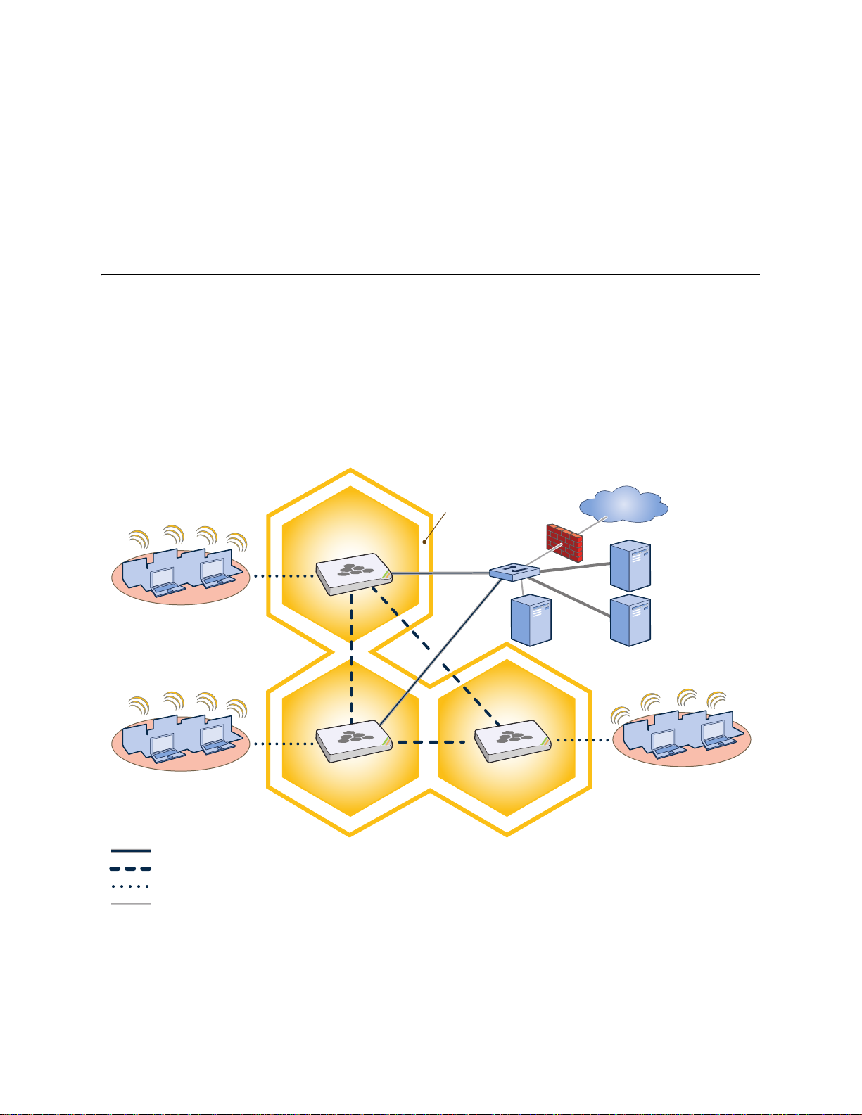
Chapter 11 Deployment Examples (CLI)
Wireless Network-1
Switch
Firewall
Internet
DHCP
Server
Wireless Network-2
Wireless Network-3
Wired Hive Backhaul Communications
HiveAP-1
HiveAP-2 HiveAP-3
Wireless Hive Backhaul Communications
Wireless Network Access Connections
The HiveAPs receive PEAP (Protected EAP) authentication requests
from clients and forward them inside RADIUS authentication packets
to the RADIUS server at 10.1.1.10. The RADIUS server is in turn
linked to the database of the Active Directory server on which all the
user accounts have previously been created and stored.
RADIUS Server
10.1.1.10
Active Directory
Server
Wired Ethernet Network Connections
Hive1
Step 4 Configure wireless clients
Define the "employee" SSID on all the wireless clients in wire less network-2 and -3. Spe cify WPA-PSK for network
authentication, AES or TKIP for data encryption, and the preshared key N38bu7Adr0n3.
The setup of hive1 is complete. Wireless clients can now associate with the HiveAPs using SSID "employee" and
access the network. The HiveAPs communicate with each other to share client associations (to support fast roaming)
and routing data (to select optimal data paths).
EXAMPLE 3: USING IEEE 802.1X AUTHENTICATION
In this example, you use a Microsoft AD (Active Directory) server and a RADIUS server to authenticate wireless
network users. To accomplish this, you make the following modifications to the hive s e t up in "Deploying a Hive":
• Configure settings for the RADIUS server on the HiveAPs
• Change the SSID parameters on the HiveAPs and wireless clients to use IEEE 802.1X
The basic network design is shown in Figure 3.
Figure 3 Hive and 802.1X Authentication
170 Aerohive
Page 71

EXAMPLE 3: USING IEEE 802.1X AUTHENTICATION
Note: This e xample a ssum es that th e RADIUS an d AD s erver s wer e prev iously co nfigured a nd po pulat ed with user
accounts that have been in use on a wired network (not shown). The only additional configuration on these
servers is to enable the RADIUS server to accept authentication requests from the HiveAPs.
Step 1 Define the RADIUS server on the HiveAP-1
Configure the settings for the RADIUS server (IP address and shared secret) on HiveAP-1.
aaa radius-server first 10.1.1.10 shared-secret s3cr3741n4bl0X
The IP address of the RADIUS server is 10.1.1.10, and the shared secret that HiveAP-1 and the RADIUS
server use to authenticate each other is "s3cr3741n4b10X". You must also enter the same shared secret
on the RADIUS server when you define the HiveAPs as access devices (see step 5).
Step 2 Change the SSID on HiveAP-1
1. Change the authentication method in the SSID.
ssid employee security protocol-suite wpa-auto-8021x
save config
The protocol suite requires WPA (Wi-Fi Pr otected Access) or WPA2 security protocol for authentication
and key management, AES or TKIP encryption, and user authentication through IEEE 802.1X.
2. Enter the show interface mgt0 command and note the dynamically assigned IP address of the mgt0
interface. You need to know this address to define HiveAP-1 as an access device on the RADIUS server in step 5.
exit
Step 3 Configure HiveAP-2 and HiveAP-3
1. Log in to HiveAP-2 through its console port.
2. Configure HiveAP-2 with the same commands that you used for HiveAP-1:
aaa radius-server first 10.1.1.10 shared-secret s3cr3741n4bl0X
ssid employee security protocol-suite wpa-auto-8021x
save config
Note: Although all HiveAPs in this example use the same shared secret, they can also use different secrets.
3. Enter the show interface mgt0 command to learn its IP address. You need this address for step 5.
exit
4. Log in to HiveAP-3 and enter the same commands.
Step 4 Modify the SSID on the wireless clients
Modify the "employee" SSID on all the wireless clients in wireless network-2 and -3. Specify WPA or WPA2 for network
authentication, AES or TKIP for data encryption, and PEAP (Protected EAP) for user authentication.
Deployment Guide 171
Page 72
Chapter 11 Deployment Examples (CLI)
Check that the MAC and IP
addresses in the table match
those of the wireless client .
Check that the authentication and
encryption modes match those in
the SSID security protocol suite.
show ss
id employee station
Chan=channel number; Pow=Power in dBm;
A-Mode=Authentication mode; Cipher=Encryption mode;
A-Time=Associated time; Auth=Authenticated;
UPID=User profile Identifier; Phymode=Physical mode;
Mac Addr IP Addr Chan Tx Rate Rx Rate Pow A-Mode Cipher A-Time VLAN Auth UPID Phymode
-------------- ---------- ---- ------- ------- --- -------- ------- -------- ---- ---- ---- ------0016:cf8c:57bc 10.1.1.73 1 54M 54M -40 8021x aes ccm 00:02:34 1 Yes 0 11b/g
Total station
count: 1
Step 5 Configure the RADIUS Server to accept authentication requests from the HiveAPs
Log in to the RADIUS server and define the three HiveAPs as access devices. Enter their mgt0 IP addresses (or
fully-qualified domain names) and shared secret.
Step 6 Check that clients can form associations and access the network
1. To check that a client can associate with a HiveAP and access the network, open a wireless client application
and connect to the "employee" SSID. Then contact a network resource, such as a web serve r.
2. Log in to the HiveAP CLI, and check that you can see the MAC address or the associated client and an indication
that the correct SSID is in use by entering the following command:
Note: You can also enter the following commands to check the association status of a wireless client:
show auth, show roaming cache, and show roaming cache mac <mac_addr>.
The setup for using IEEE 802.1X is complete. Wireless clients can now associate with the HiveAP using SSID
"employee", authenticate themselves through IEEE 802.1X to a RADIUS server, and access the network.
172 Aerohive
Page 73

EXAMPLE 4: APPLYING QOS
EXAMPLE 4: APPLYING QOS
In this example, you want the hive members to prioritize voice, streaming media, and e-mail traffic. First, you map
distinguishing elements of these traffic types to three Aerohive QoS (Quality of Service) classes:
Class 6: voice traffic from VoIP phones with MAC OUI 00:12:3b (the OUI for all phones in the network)
Voice traffic is very sensitive to delay and cannot tolerate packet loss without loss of voice quality. When
other traffic is competing with voice traffi c for bandwidth , it becomes e ssential to prevent that traffic from
interfering with voice traffic. Because voice tra ffic for a single call requires very little bandwidth—typically
from 8 to 64 Kbps depending on the voice codec used—a good approach for setting its rate is to calculate
the bandwidth necessary for a voice call plus related telephony traffic from a single user’s computer,
softphone, or handset and then multiply that by the potential number of concurrent VoIP users.
Class 5: streaming media using the MMS (Microsoft Media Server) protocol on TCP port 1755
Although streaming media is also time sensitive, streaming media software for both clients and servers
offers limited buffering to prevent choppy sounds and pixelated video when network congestion occurs.
Because congestion for more than a few seconds can adversely effect streaming media, it is important to
assign this type of traffic a higher priority than other types, but its priority should be lower than that for
voice, which is even more sensitive to delay.
Class 3: data traffic for e-mail using the following protocols:
SMTP (Simple Mail Transfer Protocol) on TCP port 25
POP3 (Post Office Protocol version 3) on TCP port 110
Then you create classifier profiles that reference these traffic-to-class mappings. You bind the profiles to the
wifi0.1 and eth0 interfaces so that hive members map the traffic matching these profiles that arrives at these
interfaces to the proper Aerohive classes.
You next define a QoS policy that defines how the hive members prioritize and process the traffic mapped to
Aerohive classes 6, 5, and 3. The QoS policy (named "voice") is shown in Fi gure 4 on page 174 and has these settings:
Class 6 (voice)
Forwarding: strict (Hive members forward traffic mapped to this class immediately without queuing it.)
Maximum rate for all class 6 traffic: 512 Kbps, which supports an 8- to 64-Kbps VoIP call (depending on the
compression that the codec provides) plus other telephony traffic such as DHCP, DNS, HTTP, and TFTP.
Class 5 (streaming media)
Forwarding: WRR (weighted round robin) with a weight of 90
By assigning class 5 a higher weight (90) than class 3 and 2 weights (class 3 = 60, class 2 = 30), you give
streaming media roughly a 3:2 priority over class 3 traffic and a 3:1 priority over class 2 traffic.
Maximum traffic rate for all class 5 traffic: 20,000 Kbps
You change the bandwidth available for streaming media when there is no competition for it (the
default rate for class 5 is 10,000 Kbps on HiveAPs that do not support the IEEE 802.11n standard and
50,000 Kbps on HiveAPs that do. However , you do not set the maximum rate (54,000 or 1,000,000 Kbps,
depending on the HiveAP model that you are configuring) to ensure that streaming media does not
consume all available bandwidth even if it is available.
Class 3 (e-mail)
Forwarding: WRR with a weight of 60
To help ensure that e-mail traffic remains flowing even when other types of data traffic compete with it
for available bandwidth, you elevate its priority by mapping SMTP and POP3 traffic to class 3 and giving
that class a higher weight (60) than the weight for class 2 traffic (30).
Maximum traffic rate for all class 3 traffic: 54,000 or 1,000,000 Kbps (the default, de pending on the Hive AP)
Deployment Guide 173
Page 74

Chapter 11 Deployment Examples (CLI)
qos policy voice qos 6 strict 512 0
The policy assigns the highest priority to voice traffic (class 6). For each voice session up to
512 Kbps, hive members provide “strict” forwarding; that is, they forward traffic immediately
without queuing it.
Voice
qos policy voice qos 5 wrr 20000 90
Because streaming media (class 5) needs more bandwidth than voice does, the policy
defines a higher forwarding rate for it: 20,000 Kbps. It sorts streaming media into forwarding
queues using the WRR (weighted round robin) mechanism. It also prioritizes streaming media
by assigning a higher weight (90) than it assigns data traffic (class 3 = 60, class 2 = 30).
Streaming
Media
qos policy voice qos 3 wrr { 54000 | 1000000 } 60
qos policy voice qos 2 wrr { 54000 | 1000000 } 30
*
The policy sorts class 3 and 2 traffic into forwarding queues using WRR and defines the
highest forwarding rate: 54,000 Kbps or 1,000,000 Kbps, depending on the HiveAP model
that you are configuring. It gives class 3 (for e-mail protocols SMTP and POP3) a higher WRR
weight (60) so that the HiveAP queues more e-mail traffic in proportion to other types of traffic
in class 2, which has a weight of 30 by default. As a result, e-mail traffic has a better chance
of being forwarded than other types of traffic when bandwidth is scarce.
Class 2 is for all types of traffic not mapped to an Aerohive class—such as HTTP for example.
Data
QoS Policy: “voice”
* You do not need to enter this command because it just sets the default
values for class 2. It is shown to provide contrast with the previous command.
Note: The HiveAP assigns all traffic that you do not specifically map to an Aerohive class to class 2, which by
default uses WRR with a weight of 30 and a rate of 54,000 or 1,000,000 Kbps, depending on the HiveAP.
Figure 4 QoS Policy "voice" for Voice, Streaming Media, and Data
Note: This e xample a ssum es that th e RADIUS an d AD s erver s wer e prev iously co nfigured a nd po pulat ed with user
Finally, you create a user profile "employee-net" and apply the QoS policy "voice" to the user profile on each hive
member. You also configure the RADIUS server to return attributes in its authentication responses to indicate the
user group to which the hive members then assign users.
174 Aerohive
accounts and have been serving a wired network (not shown). The only additional configuration is to
enable the RADIUS server to accept authentication requests from the HiveAPs.
Page 75

EXAMPLE 4: APPLYING QOS
Step 1 Map traffic types to Aerohive QoS classes on HiveAP-1
1. Map the MAC OUI (organizational unit identifier) of network users’ VoIP phones to Aerohive class 6.
qos classifier-map oui 00:12:3b qos 6
In this example, all network users use VoIP phones from the same vendor whose OUI (that is, the MAC
address prefix ) is 00:12:3b. When HiveAP-1 receives traffic from a client whose source MAC address
contains this OUI, it assigns it to Aerohive class 6.
2. Define the custom services that you need.
service mms tcp 1755
service smtp tcp 25
service pop3 tcp 110
The MMS (Microsoft Media Server) protocol can use several transports (UDP, TCP, and HTTP). However,
for a HiveAP to be able to map a service to an Aerohive QoS class, it must be able to identify that
service by a unique characteristic such as a static destination port number or a nonstandard protocol
number. Unlike MMS/UDP and MMS/HTTP, both of which use a range of destination ports, MMS/TCP uses
the static destination port 1755, which a HiveAP can use to map the service to an Aerohive class.
Therefore, you define a custom service for MMS using TCP port 1755. Y ou also d efine custom services for
SMTP and POP3 so that you can map them to Aerohive class 3. By doing so, you can prioritize e-mail
traffic above other types of traffic that the HiveAP assigns to class 2 by default.
3. Map services to Aerohive classes.
qos classifier-map service mms qos 5
qos classifier-map service smtp qos 3
qos classifier-map service pop3 qos 3
Unless you map a specific service to an Aerohive QoS class, a HiveAP maps all traffic to class 2. In this
example, you prioritize voice, media, and e-mail traffic by assigning them to higher QoS classes than
class 2, and then by defining the forwarding and weighting mechanisms for each class (see step 3).
Step 2 Create profiles to check traffic arriving at interfaces on HiveAP-1
1. Define two classifier profiles for the traffic types "mac" and "service".
qos classifier-profile employee-voice mac
qos classifier-profile employee-voice service
qos classifier-profile eth0-voice mac
qos classifier-profile eth0-voice service
Classifier profiles define which components of incoming traffic HiveAP-1 checks. Because you specify
"mac" and "service", it checks the MAC address in the Ethernet frame header and the service type (by
protocol number in the IP packet header and port number in the transport packet header). If it detects
traffic matching a classifier-map, it maps it to the appropriate Aerohive class. However, before this can
happen, you must first associate the profiles with the interfaces that will be receiving the traffic that
you want checked. This you do with the next two commands.
Deployment Guide 175
Page 76

Chapter 11 Deployment Examples (CLI)
2. Associate the classifier profiles with the employee SSID and the eth0 interface so that HiveAP-1 can classify
incoming traffic arriving at these two interfaces.
ssid employee qos-classifier employee-voice
interface eth0 qos-classifier eth0-voice
By creating two QoS classifiers and associating them with the employee SSID and eth0 interface,
HiveAP-1 can classify traffic flowing in both directions for subsequent QoS processing; that is, it can
classify traffic flowing from the wireless LAN to the wired LAN, and from the wired LAN to the wireless
LAN.
Note: If the surrounding network employs the IEEE 802.11p QoS classification system (for wired network
traffic) or 802.11e (for wireless network traffic), you can ensure that HiveAP-1 checks for them by
entering these commands:
qos classifier-profile eth0-voice 8021p
qos classifier-profile employee-voice 80211e
Step 3 Apply QoS on HiveAP-1
1. Create a QoS policy.
For HiveAPs supporting IEEE 802.11a/b/g:
qos policy voice qos 5 wrr 20000 90
qos policy voice qos 3 wrr 54000 60
For HiveAPs supporting IEEE 802.11a/b/g/n:
qos policy voice qos 6 strict 512 0
qos policy voice qos 5 wrr 20000 90
qos policy voice qos 3 wrr 1000000 60
By default, a newly created QoS policy attempts to forward traffic mapped to classes 6 and 7
immediately upon receipt. This immediate forwarding of received traffic is called "strict" forwarding. To
assign strict forwarding to VoIP traffic from phones whose MAC OUI is mapped to class 6, you simply
retain the default settings for class 6 traffic on HiveAPs supporting 802.11a/b/g data rates. For HiveAPs
supporting 802.11n data rates, the default user profile rate is 20,000 Kbps for class 6 traffic, so you
change it to 512 Kbps.
For classes 5 and 3, you limit the rate of traffic and set WRR (weighted round robin) weights so that the
HiveAP can control how to put the rate-limited traffic into forwarding queues. You use the default
settings for class 2 traffic.
When you enter any one of the above commands, the HiveAP automatically sets the maximum
bandwidth for all members of the user group to which you later apply this policy and the bandwidth for
any individual group member. You leave the maximum traffic rate at the default 54,000 Kbps or
1,000,000 Kbps—depending on the HiveAP model that you are configuring—for the user group. You also
leave the maximum bandwidth for a single user at 54,000 or 1,000,000 Kbps, so that if a single user
needs all the bandwidth and there is no competition for it, that user can use it all.
Also by default, the traffic rate for this policy has a weight of 10. At this point, because this is the only
QoS policy, the weight is inconsequential. If there were other QoS policies, then their weights would
help determine how the HiveAP would allocate the available bandwidth.
176 Aerohive
Page 77

EXAMPLE 4: APPLYING QOS
The QoS policy that you define is shown in Figure 5. Although you did not configure settings for Aerohive QoS
classes 0, 1, 2, 4, and 7, the policy applies default settings to them. The HiveAP assigns all traffic that you do
not specifically map to an Aerohive class to class 2, which uses WRR with a weight of 30 and a default rate of
54,000 or 1,000,000 Kbps. Because nothing is mapped to classes 0, 1, 4, and 7, their settings are irrelevant.
Figure 5 QoS Policy "voice"
The user profile rate defines the total amount of bandwidth for all users to
which this policy applies. The user rate defines the maximum amount for any
single user. The user rate can be equal to but not greater than the user profile
rate. (Note: The maximums shown here are for HiveAPs that support 802.11n
data rates. For other HiveAPs, the maximum rates are 54,000 Kbps.)
show qos policy voice
Policy name=voice; user rate limit=1000000kbps;
User profile rate=1000000kbps; user profile weight=10;
Class=0; mode=wrr; weight=10; limit=1000000kbps;
Class=1; mode=wrr; weight=20; limit=1000000kbps;
Class=2; mode=wrr; weight=30; limit=1000000kbps;
Class=3; mode=wrr; weight=60; limit=1000000kbps;
Class=4; mode=wrr; weight=50; limit=1000000kbps;
Class=5; mode=wrr; weight=90; limit=20000kbps;
Class=6; mode=strict; weight=0; limit=512kbps;
Class=7; mode=strict; weight=0; limit=20000kbps;
The forwarding mode for class 6 (voice)
is strict. The HiveAP forwards packets
belonging to this class immediately
without queuing them.
The forwarding mode for class 5 (streaming media) and 2 - 3
(data) is WRR (weighted round robin). The HiveAP forwards
traffic belonging to these classes by putting them into
forwarding queues. The weights determine how many bits per
second go into each queue. For every 30 bits that the HiveAP
queues for class 2, it queues approximately 60 bits for class 3,
and 90 bits for class 5. These amounts are approximations
because the HiveAP also has an internal set weights for traffic
in different classes that skews forwarding in favor of traffic
belonging to higher classes.
2. Create a user profile and apply the QoS policy to it.
user-profile employee-net qos-policy voice attribute 2
You apply the QoS policy "voice" to all users belonging to the user-profile "employee-net" with attribute
2. On the RADIUS server , you must configure attribute 2 as one of the RADIUS attributes that the RADIUS
server returns when authenticating users (see step 5 on page 179).
Note: When HiveAP-1 does not use RADIUS for user authentication, you must assign the user profile to an
SSID. To do that, use the following command: ssid employee default-user-profile-attr 2
save config
exit
Deployment Guide 177
Page 78

Chapter 11 Deployment Examples (CLI)
Step 4 Configure HiveAP-2 and HiveAP-3
1. Log in to HiveAP-2 through its console port.
2. Configure HiveAP-2 with the same commands that you used for HiveAP-1:
qos classifier-map oui 00:12:3b qos 6
service mms tcp 1755
service smtp tcp 25
service pop3 tcp 110
qos classifier-map service mms qos 5
qos classifier-map service smtp qos 3
qos classifier-map service pop3 qos 3
qos classifier-profile employee-voice mac
qos classifier-profile employee-voice service
qos classifier-profile eth0-voice mac
qos classifier-profile eth0-voice service
ssid employee qos-classifier employee-voice
interface eth0 qos-classifier eth0-voice
For HiveAPs supporting IEEE 802.11a/b/g:
qos policy voice qos 5 wrr 20000 90
qos policy voice qos 3 wrr 54000 60
For HiveAPs supporting IEEE 802.11a/b/g/n:
qos policy voice qos 6 strict 512 0
qos policy voice qos 5 wrr 20000 90
qos policy voice qos 3 wrr 1000000 60
user-profile employee-net qos-policy voice attribute 2
save config
exit
3. Log in to HiveAP-3 and enter the same commands.
178 Aerohive
Page 79

EXAMPLE 5: LOADING A BOOTSTRAP CONFIGURATION
Step 5 Configure RADIUS server attributes
1. Log in to the RADIUS server and define the three HiveAPs as RADIUS clients.
2. Configure the following attributes for the realm to which the wireless user accounts in network-1, -2, and -3
belong:
• Tunnel Type = GRE (value = 10)
• Tunnel Medium Type = IP (value = 1)
• Tunnel Private Group ID = 2
The RADIUS server returns the above attributes for all wireless users it authenticates from network-1, -2, and -3.
The HiveAP uses the combination of returned RADIUS attributes to assign users to the user group 2 ("employee-net").
It does not use them to create a GRE tunnel, which the tunnel type attribute might lead you to think.
When there is more traffic than available bandwidth, the HiveAP applies the "voice" policy. It performs strict
forwarding for voice and uses a WRR (weighted round robin) scheduling discipline for directing streaming media and
data traffic to queues to await forwarding. The QoS configuration is complete.
EXAMPLE 5: LOADING A BOOTSTRAP CONFIGURATION
As explained in "HiveOS Configuration File Types" on page 157, a bootstrap config file is typically a small set of
commands to which a HiveAP can revert when the configuration is reset or if the HiveAP cannot load its curren t and
backup configs. If you do not define and load a bootstrap config, the HiveAP reverts to the default config in these
situations, which can lead to two potential problems:
• If both the current and backup configs fail to load on a HiveAP acting as a mesh point in a hard-to-reach
location—such as a ceiling crawlspace—the HiveAP would revert to the default config. Because a mesh point
needs to join a hive before it can access the network and the default config does not contain the hive settings
that the mesh point needs to join the hive, an administrator would need to crawl to the device to make a
console connection to reconfigure the HiveAP.
• If the location of a HiveA P is public ly accessible, someone could press the reset button on the front panel of the
device to return the configuration to its default settings, log in using the default login name and password
(admin, aerohive), and thereby gain complete admin access. (Note that you can disable the a bility of the re set
button to reset the configuration by entering this command: no reset-button reset-config-enable)
A bootstrap configuration can help in both of these situations. For the first case, a bootstrap config with the
necessary hive membership settings can allow the HiveAP to connect to the network and the reby become accessible
over the network for further configuring. For the second case, a bootstrap config with a number of obstacles such as
a hard-to-guess login name and password and a disabled access subinterface can make the firmware inaccessible
and the device unusable.
HiveAP-1 and -2 are in locations that are not completely secure. HiveAP-3 is a mesh p oint in a fairly inaccessible
location. To counter theft of the first two HiveAPs and to avoid the nuisance of physically accessing the third HiveAP,
you define a bootstrap config file that addresses both concerns and load it on the HiveAPs.
Deployment Guide 179
Page 80

Chapter 11 Deployment Examples (CLI)
Step 1 Define the bootstrap config on HiveAP-1
1. Make a serial connection to the console port on HiveAP-1, log in, and load the default config.
load config default
reboot
Y o u do not want the bootstrap config to contain any of your previously defined settings from the current
config. Therefore, you load the default config, which has only default settings. When you begin with
the default config and enter the commands that define the bootstrap config, the bootstrap config will
have just those commands and the default config settings.
2. Confirm the reboot command, and then, when you are asked if you want to use the Aerohive Initial
Configuration Wizard, enter no.
3. Log in using the default user name admin and password aerohive.
4. Define admin login parameters for the bootstrap config that are difficult to guess.
admin root-admin Cwb12o11siNIm8vhD2hs password 8wDamKC1Lo53Ku71
You use the maximum number of alphanumeric characters for the login name (20 characters) and
password (16 characters). By mixing uppercase and lowercase letters with numbers in strings that do
not spell words or phrases, you make the login much harder to guess.
Note: Be careful to remember the login name and password defined in a bootstrap config file. If they become
lost or forgotten, you must obtain a one-time login key from Aerohive technical support. To get the
key, you must already have had a support contract in place. The first one-time login key is free. After
that, there is a small handling fee for each additional key.
5. Leave the various interfaces in their default up or down states.
By default, the wifi0 and wifi0.1 interfaces are down, but the mgt0, eth0, wifi1, and wifi1.1
subinterfaces are up. The hive members need to use wifi1.1, whi ch is in backhaul mode, so that
HiveAP-3 can rejoin hive1 and, through hive1, access DHCP and DNS servers to regain network
connectivity. (By default, mgt0 is a DHCP client.) You leave the eth0 interface up so that Hive-1 and
Hive-2 can retain an open path to the wired network. However, with the two interfaces in access
mode—wifi0 and wifi0.1— in the down state, none of the HiveAPs will be able provide netw ork access to
any wireless clients. Wireless clients cannot form associations through wifi1.1 nor can a computer
attach through the eth0 interface—because it is also in backhaul mode—and obtain network access
through the mesh.
6. Define the hive settings so that any of the three HiveAPs using the bootstrap config can rejoin the grid.
hive hive1
hive hive1 password s1r70ckH07m3s
interface mgt0 hive hive1
When a HiveAP boots up using the bootstrap config, it can rejoin hive1 because the configuration
includes the hive name and password and binds the mgt0 interface to the hive. This is particularly
useful for HiveAP-3 because it is a mesh point and can only access the wired network after it has joined
the hive. It can then reach the wired network through either of the portals, HiveAP-1 or HiveAP-2.
7. Save the configuration as a bootstrap config.
save config running bootstrap
If anyone resets the current configuration, the HiveAP will load this bootstrap config and thwart any
thief from accessing the configuration and any wireless client from accessing the network.
180 Aerohive
Page 81

EXAMPLE 5: LOADING A BOOTSTRAP CONFIGURATION
Step 2 Save the bootstrap config to a TFTP server
1. Check the configurations to make sure the settings are accurate.
show config bootstrap
Check that the settings are those you entered in the previous step for the bootstrap config.
show config backup
Note that the backup config is the previous current config. This is the configuration that has all your
previously defined settings.
2. Return to the previous current config.
load config backup
reboot
3. When HiveAP-1 finishes rebooting, log back in using the login parameters you set in "Example 1: Deploying a
Single HiveAP" on page 162 (mwebster, 3fF8ha).
4. Check that the current config is the same as your previous current config.
show config current
5. Save the file as bootstrap-hive1.txt to the root directory of your TFTP server running on your management
system at 10.1.1.31, an address received by the same DHCP server and in the same subnet as the HiveAP
addresses.
save config bootstrap tftp://10.1.1.31:bootstrap-hive1.txt
Step 3 Load the bootstrap config file on HiveAP-2 and HiveAP-3
1. Make a serial connection to the console port on HiveAP-2 and log in.
2. Upload the bootstrap-hive1.txt config file from the TFTP server to HiveAP-2 as a bootstrap config.
save config tftp://10.1.1.31:bootstrap-hive1.txt bootstrap
3. Check that the uploaded config file is now the bootstrap config.
show config bootstrap
4. Repeat the procedure to load the bootstrap config on HiveAP-3.
The bootstrap configs are now in place on all three HiveAPs.
Deployment Guide 181
Page 82

Chapter 11 Deployment Examples (CLI)
CLI COMMANDS FOR EXAMPLES
This section includes all the CLI commands for configuring the HiveAPs in the previous exampl es. The CLI
configurations are presented in their entirety (without explanations) as a convenient reference, and—if you are
reading this guide as a PDF—as an easy way to copy and paste the commands. Simply copy the blocks of text for
configuring the HiveAPs in each example and paste them at the command prompt.
Note: The following sections omit optional commands, such a s changing the login name and password, and
commands used to check a configuration.
Commands for Example 1
Enter the following commands to configure the SSID "employee" on the single HiveAP in "Deploying a Single HiveAP"
on page 162:
ssid employee
ssid employee security protocol-suite wpa-auto-psk ascii-key N38bu7Adr0n3
interface wifi0.1 ssid employee
save config
Commands for Example 2
Enter the following commands to configure three HiveAPs as members of "hive1" in "Deploying a Hive" on page 165:
HiveAP-1
hive hive1
hive hive1 password s1r70ckH07m3s
interface mgt0 hive hive1
save config
HiveAP-2
ssid employee
ssid employee security protocol-suite wpa-auto-psk ascii-key N38bu7Adr0n3
interface wifi0.1 ssid employee
hive hive1
hive hive1 password s1r70ckH07m3s
interface mgt0 hive hive1
save config
182 Aerohive
Page 83

EXAMPLE 5: CLI COMMANDS FOR EXAMPLES
HiveAP-3
ssid employee
ssid employee security protocol-suite wpa-auto-psk ascii-key N38bu7Adr0n3
interface wifi0.1 ssid employee
hive hive1
hive hive1 password s1r70ckH07m3s
interface mgt0 hive hive1
save config
Commands for Example 3
Enter the following commands to configure the hive members to support IEEE 802.1X authentication in "Using IEEE
802.1X Authentication" on page 170:
HiveAP-1
aaa radius-server first 10.1.1.10 shared-secret s3cr3741n4bl0X
ssid employee security protocol-suite wpa-auto-8021x
save config
HiveAP-2
aaa radius-server first 10.1.1.10 shared-secret s3cr3741n4bl0X
ssid employee security protocol-suite wpa-auto-8021x
save config
HiveAP-3
aaa radius-server 10.1.1.10 shared-secret s3cr3741n4bl0X
ssid employee security protocol-suite wpa-auto-8021x
save config
Deployment Guide 183
Page 84

Chapter 11 Deployment Examples (CLI)
Commands for Example 4
Enter the following commands to configure the hive members to apply QoS (Quality of Service) to voice, streaming
media, and data traffic in "Applying QoS" on page 173:
HiveAP-1
qos classifier-map oui 00:12:3b qos 6
service mms tcp 1755
service smtp tcp 25
service pop3 tcp 110
qos classifier-map service mms qos 5
qos classifier-map service smtp qos 3
qos classifier-map service pop3 qos 3
qos classifier-profile employee-voice mac
qos classifier-profile employee-voice service
qos classifier-profile eth0-voice mac
qos classifier-profile eth0-voice service
ssid employee qos-classifier employee-voice
interface eth0 qos-classifier eth0-voice
For HiveAPs supporting IEEE 802.11a/b/g
qos policy voice qos 5 wrr 20000 90
qos policy voice qos 3 wrr 54000 60
For HiveAPs supporting IEEE 802.11a/b/g/n
qos policy voice qos 6 strict 512 0
qos policy voice qos 5 wrr 20000 90
qos policy voice qos 3 wrr 1000000 60
user-profile employee-net qos-policy voice attribute 2
save config
HiveAP-2
qos classifier-map oui 00:12:3b qos 6
service mms tcp 1755
service smtp tcp 25
service pop3 tcp 110
qos classifier-map service mms qos 5
qos classifier-map service smtp qos 3
qos classifier-map service pop3 qos 3
qos classifier-profile employee-voice mac
184 Aerohive
Page 85

qos classifier-profile employee-voice service
qos classifier-profile eth0-voice mac
qos classifier-profile eth0-voice service
ssid employee qos-classifier employee-voice
interface eth0 qos-classifier eth0-voice
For HiveAPs supporting IEEE 802.11a/b/g
qos policy voice qos 5 wrr 20000 90
qos policy voice qos 3 wrr 54000 60
For HiveAPs supporting IEEE 802.11a/b/g/n
qos policy voice qos 6 strict 512 0
qos policy voice qos 5 wrr 20000 90
qos policy voice qos 3 wrr 1000000 60
user-profile employee-net qos-policy voice attribute 2
save config
HiveAP-3
EXAMPLE 5: CLI COMMANDS FOR EXAMPLES
qos classifier-map oui 00:12:3b qos 6
service mms tcp 1755
service smtp tcp 25
service pop3 tcp 110
qos classifier-map service mms qos 5
qos classifier-map service smtp qos 3
qos classifier-map service pop3 qos 3
qos classifier-profile employee-voice mac
qos classifier-profile employee-voice service
qos classifier-profile eth0-voice mac
qos classifier-profile eth0-voice service
ssid employee qos-classifier employee-voice
interface eth0 qos-classifier eth0-voice
For HiveAPs supporting IEEE 802.11a/b/g
qos policy voice qos 5 wrr 20000 90
qos policy voice qos 3 wrr 54000 60
For HiveAPs supporting IEEE 802.11a/b/g/n
qos policy voice qos 6 strict 512 0
qos policy voice qos 5 wrr 20000 90
qos policy voice qos 3 wrr 1000000 60
user-profile employee-net qos-policy voice attribute 2
save config
Deployment Guide 185
Page 86

Chapter 11 Deployment Examples (CLI)
Commands for Example 5
Enter the following commands to create bootstrap config files and load them on the hive members in "Loading a
Bootstrap Configuration" on page 179:
bootstrap-security.txt
admin root-admin Cwb12o11siNIm8vhD2hs password 8wDamKC1Lo53Ku71
hive hive1
hive hive1 password s1r70ckH07m3s
interface mgt0 hive hive1
HiveAP-1
save config tftp://10.1.1.31:bootstrap-security.txt bootstrap
show config bootstrap
HiveAP-2
save config tftp://10.1.1.31:bootstrap-security.txt bootstrap
show config bootstrap
HiveAP-3
save config tftp://10.1.1.31:bootstrap-meshpoint.txt bootstrap
show config bootstrap
186 Aerohive
Page 87

Chapter 12 Traffic Types
This is a list of all the types of traffic that might be involved with a HiveAP and HiveManager deployment. If a
firewall lies between any of the sources and destinations listed below, make sure that it allows these traffic types.
Traffic Supporting Network Access for Wireless Clients
SRC
Service Source Destination Protocol
DHCP unregistered
wireless client
DNS unregistered
wireless client
GRE HiveAP mgt0
interface
HTTP unregistered
wireless client
HTTPS unregistered
wireless client
RADIUS
accounting
RADIUS
authentication
* DNX = dynamic network extensions
† This is the default destination port number. You can change it to a different port number from 1 to 65535.
HiveAP mgt0
interface
HiveAP mgt0
interface
HiveAP wifi
subinterface in
access mode
HiveAP wifi
subinterface in
access mode
HiveAP mgt0
interface
HiveAP wifi
subinterface in
access mode
HiveAP wifi
subinterface in
access mode
RADIUS server 17 UDP 1024 -
RADIUS server 17 UDP 1024 -
17 UDP6867Required for captive web portal
17 UDP 53, or
47 GRE N.A. N.A. Required to support DNX
6 TCP 1024 -
6 TCP 1024 -
Port
1024 65535
65535
65535
65535
65535
DST
Port
53 Required for captive web portal
80 Required for captive web portal
443 Required for captive web portal
1813†Required to support RADIUS
1812
Notes
functionality
functionality
3 roaming between members of
different hives
functionality
functionality using a server key
accounting
†
Required for 802.1X authentication
of users
*
and layer
Traffic Supporting Management of HiveAPs
SRC
Service Source Destination Protocol
CAPWAP
NTP HiveAP mgt0
* Control and Provisioning of Wireless Access Points
Deployment Guide 187
*
HiveAP mgt0
interface
interface
HiveManager
MGT or LAN
port
HiveManager
MGT or LAN
port
17 UDP 12222 12222 Required for HiveAPs to discover
17 UDP 1024 -
Port
65535
DST
Port
123 Required for HiveAP time
Notes
the HiveManager and send it
alarms, events, and reports
synchronization with the
HiveManager
Page 88

Chapter 12 Traffic T yp es
Service Source Destination Protocol
SNMP HiveAP mgt0
SNMP manager 17 UDP 1024 -
interface
SNMP traps HiveAP mgt0
SNMP manager 17 UDP 1024 -
interface
SSHv2 HiveManager
MGT port
HiveAP mgt0
interface
6 TCP 1024 -
Traffic Supporting Device Operations
Service Source Destination Protocol
Aerohive
Cooperative
Control Messages
Aerohive
Cooperative
Control Messages
AeroScout
Reports
DHCP HiveAP mgt0
HTTPS management
NTP HiveAP mgt0
SMTP HiveManager
SSHv2 management
syslog HiveAP mgt0
Telnet management
TFTP TFTP server or
HiveAP mgt0
interface
HiveAP wifi1.1
or eth0
interface
AeroScout
engine
interface
system
interface, or
HiveManager
MGT port
MGT port
system
interface
system
mgt0
HiveAP mgt0
17 UDP 3000
interface
HiveAP wifi1.1
N.A. N.A. N.A. Required for hive communications
or eth0
interface
HiveAP mgt0
17 UDP 1024 interface
DHCP server 17 UDP 68 67 By default, a HiveAP gets its IP
HiveManager
6 TCP 1024 MGT port
NTP server 6 TCP 1024 -
SMTP server 6 TCP 1024 -
HiveAP mgt0
6 TCP 1024 interface or
HiveManager
MGT port
syslog server 17 UDP 1024 -
HiveAP mgt0
interface
HiveAP mgt0
6 TCP,
17 UDP
17 UDP 1024 or TFTP server
SRC
Port
65535
65535
65535
SRC
Port
65535
65535
65535
65535
65535
65535
1024 -
65535
65535
DST
Port
Notes
161 Required for reporting alarms and
events to an SNMP manager and to
HiveManager if not using CAPWAP
162 Required for sending SNMP traps to
an SNMP manager and to
HiveManager if not using CAPWAP
22 Required for the HiveManager to
manage and upload files to HiveAPs
DST
Port
*
3000*Required for hive commun ications
Notes
and operates at layer 3
and operates at the LLC (Logical
Link Control) sublayer of layer 2
1144 Required to report tracked devices
to an AeroScout engine
address through DHCP.
443 Required for administration
through the HiveManager GUI
123 Required for time synchronization
with an NTP server
25 Required for the HiveManager to
send e-mail alerts to admins
22 Used for secure network access to
the HiveAP or HiveManager CLI, and
(SCP) for uploading files to and
downloading files from HiveAPs and
for uploading images to HiveAPs
and HiveManager
514 Required for remote logging to a
syslog server
23 Used for unsecured network access
to the HiveAP CLI
69 Used for uploading files to and
downloading files from HiveAPs
* This is the default destination port number. You can change it to a different port number from 1024 to 65535.
188 Aerohive
Page 89

Appendix A Country Codes
When the region code on a HiveAP is preset as "world", you must set a country code for the location where you
intend to deploy the HiveAP. This code determines the radio channels and po wer settings that the HiveAP can use
when deployed in that country. For HiveAPs intended for use in the United States, the region code is preset as
"FCC"—for "Federal Communicat ions Co mmis sio n"—an d t he country code is pres et for the United States. You can see
the region code in the output of the show boot-param command.
To set a country code when the region is "world", enter the following command, in which number is the
appropriate country code number: boot-param country-code number
Note: Be sure to enter the correct country code. An incorrect entry might result in illegal radio operation and
cause harmful interference to other systems.
To apply radio settings for the updated country code, reboot the HiveAP by entering the reboot command.
To see a list of the available channels available for the country code that you have set on the HiveAP, enter the
following command: show interface { wifi0 | wifi1 } channel. For example, the output for the show
interface wifi0 channel command on a HiveAP whose region code is FCC and country code is 840 (United
States) shows that channels 1 through 11 are available. If a channel does not appear in this list, you cannot
configure the radio to use it.
The following list of country codes is provided for your convenience.
Countries and Country Codes
Albania 8
Algeria 12
Argentina 32
Armenia 51
Australia 36
Austria 40
Azerbaijan 31
Bahrain 48
Belarus 112
Belgium 56
Belize 84
Bolivia 68
Bosnia and Herzegovina 70
Brazil 76
Deployment Guide 189
Brunei Darussalam 96
Bulgaria 100
Canada 124
Chile 152
China (People’s Republic of China) 156
Colombia 170
Costa Rica 188
Croatia 191
Cyprus 196
Czech Republic 203
Denmark 208
Dominican Republic 214
Ecuador 218
Egypt 818
Page 90

Appenidix A Country Codes
El Salvador 222
Estonia 233
Faeroe Islands 234
Finland 246
France 250
France2 255
Georgia 268
Germany 276
Greece 300
Guatemala 320
Honduras 340
Hong Kong (S.A.R., P.R.C) 344
Hungary 348
Iceland 352
India 356
Indonesia 360
Iran 364
Iraq 368
Ireland 372
Israel 376
Italy 380
Jamaica 388
Japan 392
Japan1 (JP1) 393
Japan2 (JP0) 394
Japan3 (JP1-1) 395
Japan4 (JE1) 396
Japan5 (JE2) 397
Japan6 (JP6) 399
Japan7 (J7) 4007
Japan8 (J8) 4008
Japan9 (J9) 4009
IJapan10 (J10) 4010
Japan11 (J11) 4011
Japan12 (J12) 4012
Japan14 (J14) 4014
Japan15 (J15) 4015
Japan16 (J16) 4016
Japan17 (J17) 4017
Japan18 (J18) 4018
Japan19 (J19) 4019
Japan20 (J20) 4020
Japan21 (J21) 4021
Japan22 (J22) 4022
Japan23 (J23) 4023
Japan24 (J24) 4024
Jordan 400
Kazakhstan 398
Kenya 404
Korea (North Korea) 408
Korea (South Korea, ROC) 410
Korea (South Korea, ROC2) 411
Korea (South Korea, ROC3) 412
Kuwa it 4 14
Latvia 428
Lebanon 422
Libya 434
Liechtenstein 438
Lithuania 440
Luxembourg 442
Macau 446
Macedonia (The Former Yugoslav Republic of
Macedonia) 807
Malaysia 458
Malta 470
Mexico 484
Monaco (Principality of Monaco) 492
Morocco 504
Netherlands 528
New Zealand 554
Japan13 (J13) 4013
190 Aerohive
Nicaragua 558
Page 91

Appenidix A Country Codes
Norway 578
Oman 512
Pakistan (Islamic Republic of Pakistan) 586
Panama 591
Paraguay 600
Peru 604
Philippines (Republic of the Philippines) 608
Poland 616
Portugal 620
Puerto Rico 630
Qatar 634
Romania 642
Russia 643
Saudi Arabia 682
Singapore 702
Slovakia (Slovak Republic) 703
Slovenia 705
South Africa 710
Spain 724
Sweden 752
Switzerland 756
Syria 760
Taiwan 1 58
Thailand 764
Trinidad y Tobago 780
Tunisia 788
Turkey 792
U.A.E. 784
Ukraine 804
United Kingdom 826
United States 840
United States (Public Safety; FCC49) 842
Uruguay 858
Uzbekistan 860
Venezuela 862
Vietnam 704
Yemen 887
Sri Lanka 144
Zimbabwe 716
Deployment Guide 191
Page 92

Appenidix A Country Codes
192 Aerohive
 Loading...