

Page 1
Aerohive QuickStart
HiveAP 330 HiveAP 350
for the HiveAP 330 and 350
This guide explains how to set up a HiveAP 330 or 350 so it can make a network connection to
HiveManager, and how to mount it on a ceiling or wall. (The HiveAP 350 with articulated antennas
is shown in the illustrations, but the instructions apply equally to the HiveAP 330 and to the HiveAP
350 with non-articulated antennas.) To register, get product documentation, and download software
updates, visit www.aerohive.com/support.
Attach the 5 GHz antennas with gray rings
to the 5 GHz connectors with gray circles...
and the 2.4 GHz antennas with white
rings to the 2.4 GHz connectors.
1
Eth0
DHCP
Connect a standard
Ethernet cable with
RJ-45 connectors
from ETH0 on the
HiveAP to a switch.
2
Ethernet
Cable
If the switch provides
Switch
Server
Some other network devices (They
might all be incorporated in the same
device, such as a router or rewall.)
PoE (Power-overEthernet), cabling the
HiveAP to the switch
will cause the HiveAP
to power on in a few
seconds.
3
After you cable the HiveAP to an Ethernet network and power it on, it automatically
attempts to get its network settings through DHCP and contact HiveManager. The process
typically takes about ve minutes to complete. If you see the HiveAP listed on the Monitor >
Access Points > HiveAPs page in the HiveManager GUI, the initial setup is complete and you
can now begin managing the HiveAP through HiveManager.
If the HiveAP does not appear in the HiveManager GUI after about ten minutes, read the
rest of this guide to understand how the HiveAP attempts to contact HiveManager and what
you can do to help establish a connection between the two devices.
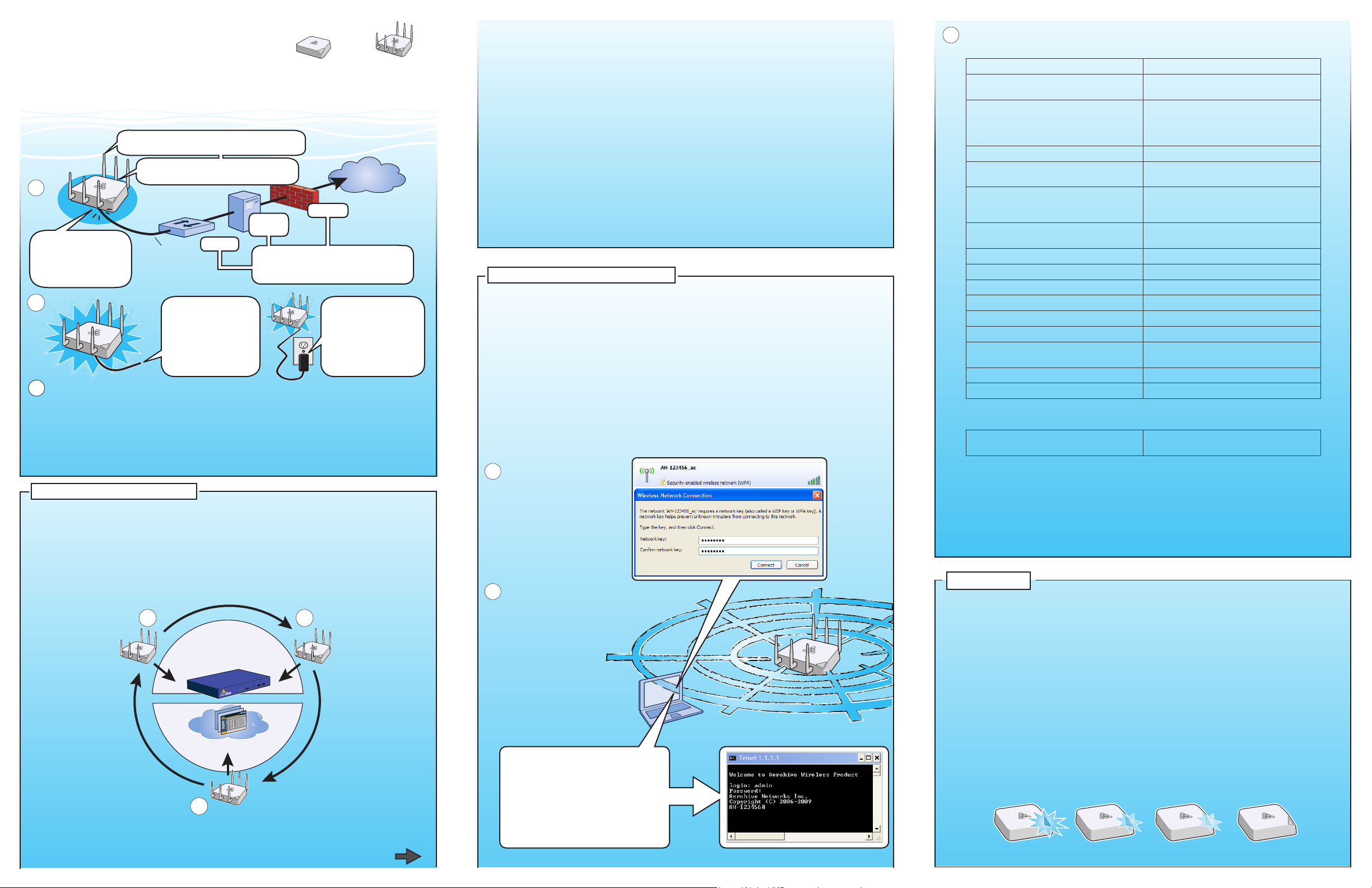
Connecting to HiveManager
By default, a HiveAP acts as a DHCP client and gets its network settings automatically from a
DHCP server. (You can also congure it with static network settings through the CLI. See the
next section, "Using the Virtual Access Console".) After a HiveAP has its network settings, it then
acts as a CAPWAP client and sends CAPWAP Discovery messages until HiveManager, acting as
the CAPWAP server, responds. CAPWAP (Control and Provisioning of Wireless Access Points) is a
protocol that access points use to contact a management device and communicate with it.
When a HiveAP goes online for the rst time without any specic CAPWAP server conguration
entered manually or received as a DHCP option, it progresses through these cycle of CAPWAP
connection attempts:
(a) The HiveAP tries to
connect to HiveManager
using the default domain
name "hivemanager.
<local_domain>:
12222", where
<local_domain> is the
domain name that a
DHCP server supplied
to the HiveAP and
12222 is the UDP port
number. If a DNS server
has been congured
to resolve that domain
name to an IP address, the
HiveAP and HiveManager
then form a secure CAPWAP
connection on port 12222.
If the HiveAP cannot make a
CAPWAP connection to HiveManager
on port 12222, it tries to reach it by
using TCP port 80: hivemanager.<local_
domain>:80.
P/N 330050-02 Rev. A
a
HiveManager
or
HiveManager Virtual
Appliance
HiveManager Online
c
HiveManager Online on UDP port 12222, it tries to reach it on
TCP port 80. If that proves unsuccessful, the HiveAP returns to
its initial search through a DNS lookup and repeats the cycle.
in its ACL (access control list), it responds
and they form a secure CAPWAP connection.
If the HiveAP cannot make a CAPWAP connection to
Firewall
b
Online at redirector.aerohive.
redirection server has a serial
number or MAC address for that HiveAP
Internet
If the switch does not
provide PoE, use the
AC/DC power adaptor
(available as an
accessory) to connect
the HiveAP to a 100240 AC power source.
(b) If the DNS server cannot
resolve the domain name
to an IP address, the
HiveAP broadcasts
CAPWAP Discovery
messages on its local
subnet. If HiveManager
is on the local network
and responds, they
form a secure CAPWAP
HiveManager produce no
results, the HiveAP tries
to contact HiveManager
com:12222. If the Aerohive
connection.
(c) If the rst two
searches for a local
A HiveAP connected directly to the network is called a portal. You can also place a HiveAP
within radio range of a portal so that it forms a wireless link through the portal to the wired
network. This kind of HiveAP is called a mesh point. A mesh point initially forms a hive with
its portal using a default hive called hive0. Through this link, the mesh point can reach the
network and get its network settings from the DHCP server. Then it can form a CAPWAP
connection with HiveManager. (To add mesh points after changing the hive name, rst
connect them to the wired network. Next, push the conguration with the new hive name and
password to them from HiveManager. Finally, deploy them as mesh points.)
If the HiveAP forms a CAPWAP connection with the Aerohive redirection server and its serial
number has been entered in an ACL, the redirection server automatically redirects the
CAPWAP connection to the corresponding HiveManager Online VHM (virtual HiveManager).
The redirection server does this by sending the HiveAP the HiveManager domain name or IP
address as its new CAPWAP server and the name of the appropriate VHM. If the HiveAP is
currently using HTTP, the redirection server includes the conguration needed for the HiveAP
to continue using it. Similarly, if the HiveAP is congured to access the public network through
an HTTP proxy server, the redirection server saves the relevant settings on the HiveAP so it
will continue using the HTTP proxy server when connecting to HiveManager.
If the Aerohive redirection server does not have the HiveAP serial number, the ACL ignores the
CAPWAP connection attempts, and the HiveAP repeats the connection cycle shown previously.
Using the Virtual Access Console
As explained in the previous section, after connecting a HiveAP to the network and powering
it on, it acts as a DHCP client and tries to get its network settings automatically from a DHCP
server in VLAN 1. However, if there is no DHCP server in that VLAN, if the native VLAN for the
network segment is not 1, or if you just want to assign it a static IP address, then you need to
access the CLI and dene the network settings yourself.
One approach is to use a console cable, which is available from Aerohive as an accessory.
Another is to use the virtual access console. This is a way of accessing the CLI on a HiveAP
wirelessly through a special SSID that the HiveAP, by default, automatically activates for
administrative access when it has no conguration and cannot reach its default gateway.
The default virtual access console SSID name is “<hiveap-hostname>_ac”. The default host
name of a HiveAP consists of "AH-" plus the last six digits of its MAC address; for example,
AH-123456. In this case, the name of the default virtual access console SSID would be "AH123456_ac". By default, this SSID uses aerohive as the PSK (preshared key) for authenticating
user access. To access the virtual access console, do the following:
Using your wireless client,
4
scan for wireless networks.
If you are within range, an
SSID such as "AH-123456_ac"
appears.
Select it, and when
prompted to enter a
network key, type aerohive
and then click Connect.
Check the IP address of the
5
default gateway that the
DHCP server on the HiveAP
assigned your client. Then
make an SSH or Telnet
connection to the HiveAP
at that IP address.
(Note that the Telnet
connection is protected by
WPA2 security mechanisms.)
When prompted to enter your
credentials, enter the default
Aerohive login name (admin)
and password (aerohive).
C:\>ipcong
Windows IP Conguration
Ethernet adapter Wireless
Network Connection:
Connection-specic DNS Sufx . :
IP Address. . . . . . : 1.1.1.2
Subnet Mask . . . . . : 255.255.255.0
Default Gateway . . . : 1.1.1.1
C:\>telnet 1.1.1.1
Beacons
Wireless
Client
Beacons
6
After logging in to the virtual access console, you can view the status of various
functions and make conguration changes. Here are some commonly used commands:
Use these commands: To do the following:
show interface
Check the status of both wired and
wireless interfaces
show interface mgt0
See the network settings (IP address,
netmask, default gateway) and VLAN
ID of the mgt0 interface, which is the
management interface of the HiveAP
no interface mgt0 dhcp client
interface mgt0 ip <ip_addr>
<netmask>
interface mgt0 native-vlan <id>
Disable the DHCP client
Set the IP address and netmask of the
mgt0 interface
Set the native (untagged) VLAN that the
switch infrastructure in the surrounding
wired and wireless network uses
interface mgt0 vlan <id>
Set the VLAN for management and
control trafc
show capwap client
show hive
show hive <string> neighbor
hive <string> ...
show ssid
ssid <string> ...
interface { wi0 | wi1 } ssid
<string>
save cong
reboot
See CAPWAP client settings and status
See the hive name
Check for any neighboring hive members
Create a hive and set its parameters
See a list of all SSID names
Congure an SSID
Bind an SSID to a wireless interface in
access mode
Save the conguration to ash
Reboot the HiveAP
Only set the following command when managing HiveAPs through HiveManager or
HiveManager Virtual Appliance. Do not use it with HiveManager Online.
capwap client server name
<string>
Set the IP address or domain name of the
CAPWAP server (HiveManager)
To see a list of commands, and their accompanying CLI Help, type a question mark ( ? ).
For example, to see all the show commands, enter show ?
If you want to nd a command that uses a particular character or string of characters,
you can do a search using the following command: show cmds | include
<string>, where <string> is the word or string of characters you want to nd.
Device- and platform-specic CLI reference guides are available online. (To learn how to
access them, see "Where to go for more information" elsewhere in this document.)
Status LED
The status LED in the corner of the HiveAP 330 and 350 indicates various states of activity
through its color and illumination patterns (solid or ashing). The meanings of the colors
are explained below.
• Dark: There is no power or the status indicator is disabled.
• Blue: (solid) The device is booting up or there is no backhaul link; (ashing) the
device is shutting down
• Green: The default route is through the backhaul Ethernet interface, but not all
conditions for normal operations (white) have been met.
• Yellow: The default route is through a backhaul wi interface, but not all conditions
for normal operations (white) have been met.
• White: The device is powered on and the rmware is operating normally; that is, a
wireless interface in access mode is up, a wired or wireless backhaul link is up, and
the HiveAP has a CAPWAP connection to HiveManager.
• Purple: A new image is being loaded from HiveManager or a management AP.
• Orange: An alarm indicating a rmware or hardware issue has occurred.
You can adjust its brightness level from bright (the default) to soft to dim, or turn it off
completely. In HiveManager, the setting is on the Conguration > Management Services >
Management Options page. CLI: [ no ] system led brightness { soft | dim | off }.
Bright Soft Dim Off
Page 2

Mounting the HiveAP 330 and 350
Surface Mount
Deployment and Conguration Tips
Using the rail mount, you can mount the HiveAP 330 or 350 to the tracks of a dropped ceiling grid.
Using the mounting plate, you can mount it to any at surface that can support its weight (HiveAP
330: 1.5 lb or 0.68 kg; HiveAP 350: 2.375 lb or 1.08 kg). Both mounting options are explained
below. (The HiveAP 330 is shown in these illustrations, but the instructions apply to both models.)
Note: In addition to these methods, you can also mount the HiveAP on a table using the set
of four rubber feet that ship with the product. Simply peel the rubber feet off the
adhesive sheet and press them against the underside of the HiveAP in its four corners.
Ceiling Mount
To mount the HiveAP 330 or 350 to a standard 15/16"-wide track (2.38 cm) in a dropped ceiling,
use one of the two rail mounts that ship with the HiveAP, depending on whether the track is ush
with the ceiling tiles or recessed. You also need a drill and—most likely—a ladder.
Nudge the ceiling tiles slightly away from the track to clear some space, and then attach the
appropriate rail mount to the ceiling track. When you have the rail mount in the correct location,
cut or drill a hole in the ceiling through which you can then pass the Ethernet and power cables.
Press the the rail mount upward against the ceiling track so that the track contacts the
1
two pressure tabs and pushes them ush with the rail mount.
Rail Mount
(bird's eye view with
Ceiling Track
2
Rotate the rail mount until the
two pressure tabs click into place,
gripping the ceiling track.
In the open space in the L-shaped rail
3
mount, drill a hole in the ceiling tile
(not shown). Then pass one or both
Ethernet cables through the hole, and
if you plan to supply power from an AC
power source rather than through PoE,
pass the power cable through as well.
Connect the cables and then attach the HiveAP to the rail mount to complete the installation.
For the HiveAP 350, attach the articulted antennas and swivel them into a vertical position
pointing downward to provide optimal coverage.
With the HiveAP upside down, connect the cables (not shown). Align the two V-shaped
4
tabs and the security screw hole extension on the rail mount with the tab slots and
security screw cavity on the HiveAP, and press the HiveAP upward until it snaps into place.
(side view)
V-shaped Tab V-shaped Tab
Tab Slot Tab Slot
When done, adjust the ceiling tiles back into their former position.
CLICK!
ceiling tiles removed and
the ceiling track shown as
transparentfor clarity)
CLICK!
Security Screw
Hole Extension
Security Screw
Cavity
You can use the mounting plate to attach the HiveAP to any surface that supports its weight, and
to which you can screw or nail the plate. First, mount the plate to the surface. Then, in the open
space in the L-shaped mounting plate, make a hole in the wall so that you can pass the cables
through to the HiveAP. Finally, attach the device to the plate, connect the cables, and for the
HiveAP 350, attach the antennas.
Mount the HiveAP on a wall as explained below.
With the two exible V-shaped tabs at
1
the sides of the plate extending away
from the surface, attach the mounting
plate to a secure object such as a wall,
ceiling, post, or beam.
(bird's eye view)
V-shaped Tab V-shaped Tab
Tab Slot
Cut or drill a hole in the wall in the
2 3
open space in the L-shaped mounting
plate, pass the cables through to the
HiveAP, and connect them. (You can
also run the cables along the wall to
the HiveAP instead of through a hole.)
Depending on how the device is
powered and how it connects to the
network, connect a power cable
and one or two Ethernet cables.
(The cables are not shown in the
illustration.)
Note: There are various holes through
which you can screw or nail the
plate in place. Choose the two or
three that best suit the object to
which you are attaching it.
Security Tab
Extension
Tab Slot
Security Screw
Cavity
Align the tabs and security tab
extension on the mounting plate with
the tab slots and security screw cavity
on the HiveAP.
Push the the HiveAP against the mounting
4
plate until the tabs click inside the tab
slots.
For the HiveAP 350, attach either the
articulated or non-articulated antennas.
When using the articulated antennas,
orient them vertically for best coverage.
Locking the HiveAP
To lock the HiveAP to the rail mount or mounting plate, use either a Kensington lock or the
security screw that is included with the mounting kit. To use a Kensington lock, loop the cable
attached to the lock around a secure object, insert the T-bar component of the lock into the
device lock slot on the HiveAP, and then turn the key to engage the lock mechanism.
To lock the HiveAP to the rail mount or mounting plate or to lock the USB port cover, use the
security screw, which is included in the mounting kit. You also need a drilled spanner insert
bit for size #6 security screws and a screw driver that will accept the bit. The correct bits are
available from Aerohive in sets of three (AH-ACC-SEC-BIT-330-350-3PK).
To use the security screw, follow the steps below:
If you want to hide the USB
1
port, attach the USB port
cover by pushing the tab on
the cover into the port.
Insert the security screw
2
through the hole in the cover
and the hole in the chassis.
Using a screwdriver with a
drilled spanner bit, fasten the
screw to the security tab extension
on the rail mount. (If you want
to expose the USB port, use the
security screw without the cover.)
USB Port
USB Port Cover
Security Screw
Screwdriver
Rail Mount
or
Mounting
Plate
Security Tab
Extension
Lock Slot
The following are some tips and suggestions to help you troubleshoot a few common problems that
might arise when setting up the HiveAP 330 and 350:
• For the HiveAP 350, make sure that you connect the 2.4 GHz antennas to the 2.4 GHz
connectors, and the 5 GHz antennas to the 5 GHz connectors.
• If you manage the HiveAP through HiveManager Online and it does not show up on the Monitor
> Access Points > HiveAPs page, do the following:
– Check if the HiveAP serial number is listed in the ACL (access control list) on the Aerohive
redirection server. Log in to myhive.aerohive.com, and then click Redirector > Monitor
> HiveAP Access Control List). If not, click Enter, type its serial number in the HiveAP
Serial Number eld, and then click Save. When done, reboot the HiveAP.
– Check connectivity to Aerohive redirection server:
ping redirector.aerohive.com (Check connectivity from the HiveAP network)
capwap ping redirector.aerohive.com (Check connectivity through CAPWAP)
– Ensure that any intervening rewalls allow one of the following sets of services from the
HiveAP to HiveManager Online:
CAPWAP (UDP 12222), SSH (TCP 22), and HTTPS (TCP 443)
or
HTTP (TCP 80) and HTTPS (TCP 443)
• If a wireless client cannot form an association with an SSID, check that the client is within
range and that it is congured to use the same authentication method as the SSID. For
example, if the client is congured to use Open or WEP authentication but the SSID is
set for WPA or WPA2, the client will not be able to associate with the HiveAP. To see the
security settings for an SSID, log in to HiveManager, click Conguration>SSIDs>ssid_name
> Advanced Access Security Settings, and look at the SSID access security type, the key
management method, and the encryption method.
• If the client associates and authenticates itself, but the HiveAP cannot forward trafc,
check that the HiveAP is assigning the correct user prole and, if so, that it is also assigning
the correct VLAN. To see the user prole and VLAN that a HiveAP assigns a client, log in to
HiveManager, click Monitor > Clients > Active Clients > client_mac_address. Check the user
prole attribute and VLAN. If those are correct, then check that the client has received its
network settings through DHCP. To check connectivity to a DHCP server, click Tools > VLAN
Probe, choose the HiveAP with which the client is associated from the HIveAP drop-down list,
enter IDs for the VLAN range that you want to check. Click Start to send a DHCP DISCOVER
message, and see if it elicits a response. Also check that the VLAN conguration for the port
on the connecting switch is correct.
To remove all settings and return the conguration to its factory default settings, enter the
reset cong command or use a pin to press the Reset button, which is located near the ETH0
port on the underside of the chassis, and hold it down for at least 10 seconds.
Where to go for more information
Technical Documentation
Aerohive provides various technical documents for its products. For information about CLI
commands, see the CLI reference guides available in HTML format. For information about
HiveManager and HiveAP hardware and software topics, see the Aerohive Deployment Guide
(PDF). The deployment guide contains information about HiveAPs and HiveManager appliances,
WLAN deployment considerations, and detailed conguration instructions for commonly used
features. To access Aerohive product documentation, visit www.aerohive.com/techdocs.
HiveManager Help System
The HiveManager Help system contains a wealth of information about all the features you can
congure through HiveManager. To access it, click the Help icon in the upper right corner of
the GUI. A Help topic that pertains to the currently active GUI page appears. To see other Help
topics, use the table of contents to browse the system or the search tool to nd information
about a specic subject.
Support Site
Access technical support services, documentation, and software at www.aerohive.com/support/
login.html. After registering for an account, you will receive a user name and password to enter
when logging in. You can contact Support for assistance through the web site or by phone (+1
408.510.6100 or 866.365.9918).
Training
Aerohive offers courses covering the Aerohive cooperative control concepts, the installation and
conguration of Aerohive products, and how to troubleshoot issues and optimize performance.
For more information, visit www.aerohive.com/support/training.html.
Aerohive also offers CBT (computer-based training) modules. CBTs are online ash tutorials that
explain Aerohive concepts and walk you through conguration procedures step by step. You
can use the CBTs to familiarize yourself with the HiveManager GUI and learn how to congure
HiveAPs. Aerohive CBTs are available for free online at www.aerohive.com/techdocs.
©
2011 Aerohive Networks, Inc.
Aerohive® and HiveAP® are U.S. registered
trademarks of Aerohive Networks, Inc.
P/N 330050-02 Rev. A
Page 3

Aerohive HiveAP Compliance Information
Federal Communication Commission Interference
Statement
Aerohive products that show an FCC identifier on the product label
(FCC ID: WBV-<model_name>) comply with part 15 of the FCC Rules
when operating under the following restrictions: (1) they do not cause
harmful interference, and (2) they must accept any RF interference
received, including interference that might cause an unwanted impact
on their operation.
This equipment has been tested and found to comply with the limits for
a Class B digital device, pursuant to Part 15 of the FCC Rules. These
limits are designed to provide reasonable protection against harmful
interference in a residential installation. This equipment generates,
uses and can radiate radio frequency energy and, if not installed and
used in accordance with the instructions, may cause harmful
interference to radio communications. However, there is no guarantee
that interference will not occur in a particular installation. If this
equipment does cause harmful interference to radio or television
reception, which can be determined by turning the equipment off and
on, the user is encouraged to try to correct the interference by one of
the following measures:
• Reorient or relocate the receiving antenna
• Increase the separation between the equipment and receiver
• Connect the equipment into an outlet on a circuit different from
that to which the receiver is connected
• Consult the dealer or an experienced radio/TV technician for help
FCC Caution: Any changes or modifications not expressly approved by
the party responsible for compliance could void the user's authority to
operate this equipment. This device complies with Part 15 of the FCC
Rules. Operation is subject to the following two conditions: (1) This
device may not cause harmful interference, and (2) this device must
accept any interference received, including interference that may
cause undesired operation.
In compliance with FCC Part 15 regulations, the HiveAP automatically
discontinues transmission if there is no valid information to transmit or
if there is an operational failure.
Important: FCC Regulatory Warnings Notice
This equipment is restricted to indoor use due to its operation in 5 GHz
frequencies, which are shared by mobile satellite systems and
government radar systems. The FCC requires that this product only be
used indoors to reduce the potential for harmful interference with cochannel radar that might be operating in the 5.25-5.35 or 5.47-5.725
GHz frequency ranges in the same area. The conflicting activity of
radar stations and this device can cause interference or damage to each
other. In addition, this device has a radar detection function that might
interrupt normal operations when it detects a radar signal.
To reduce the risk of interference even further, installing this device
away from windows is recommended.
DFS certification for Aerohive products is underway but is not complete
at the time of this writing (1/2011). Contact Aerohive Technical Support
for further information. After DFS certification is complete, these
statements will hold true: This equipment complies with the FCC DFS
(Dynamic Frequency Selection) rules documented in FCC 06-96 and KDB
443999. The 5 GHz radio uses channels 36 to 48 (5.180 to 5.240 GHz)
and channels 149 to 165 (5.725 to 5.825 GHz), as well as channels
within the DFS operating frequency ranges: 52 to 64 (5.25 to 5.35 GHz),
100 to 116 (5.47 to 5.59 GHz), and 132 to 140 (5.66 to 5.725 GHz). The
frequency range 5.6 - 5.65 GHz is excluded from use. The maximum
transmit power for channels from 36 to 48 is 15 dBm in the FCC region.
Because this maximum is enforced by HiveOS, the HiveAP automatically
limits the power to 15 dBm even if the setting is greater than that.
The FCC region code is set in the device during the manufacturing
process, the option to set it to any region other than FCC is disabled,
and the country code selection function has been completely removed
from all U.S. models. It is impossible for the end user to change the
region to anything other than FCC.
Only attach antennas that are certified for use with this device.
Replacing antennas with unauthorized, high-gain antennas greatly
increases the risk of interference and invalidates the FCC certification.
The use of any devices not approved by the FCC is illegal.
Industry Canada
Note: The term "IC" before the radio certification number signifies that
Industry Canada technical specifications were met.
Products that show an Industry Canada identifier on the product label
(IC: 7774A-<model_name>) can be operated in Canada under the
following restrictions:
• The device must not cause interference and must accept any
interference, including that which might cause an unwanted
impact on the operation of the device.
• To reduce potential radio interference to other users, the antenna
type and its gain must be chosen so that the EIRP (equivalent
isotropically radiated power) is not more than that permitted for
successful communication.
• The use of the Unlicensed National Informational Infrastructure
(UNII) band UNII-1 (5.15-5.25 GHz; channels 36-48) must be
limited to indoor deployments to reduce the potential for harmful
interference with co-channel mobile satellite systems.
• To meet Industry Canada requirements, the UNII-2 band (5.25-5.35
GHz; channels 52-64) and UNII-2 Extended band (5.47-5.725 GHz;
channels 100-116, 132-140) are disabled.
• The maximum permitted antenna gain for operation in the UNII-3
band (5.725-5.825 GHz; channels 149-165) must comply with EIRP
limits specified for point-to-point and non point-to-point
operation as stated in the Industry Canada Radio Standards
Specification RSS-210, section A9.2(3).
Class B
This digital apparatus does not exceed the Class B limits for radio
noise emissions from digital apparatus as set out in the
interference-causing equipment standard entitled "Digital
Apparatus," ICES-003 of Industry Canada.
Cet appareil numérique respecte les limites de bruits
radioélectriques applicables aux appareils numériques de Classe B
prescrites dans la norme sur le matériel brouilleur: "Appareils
Numériques," NMB-003 édictée par l'Industrie.
Important: Radiation Exposure Statement
This equipment complies with radiation exposure limits set forth for an
uncontrolled environment. This equipment should be installed and
operated with a minimum distance of 20 centimeters (8 inches)
between the radiator and your body. This transmitter must not be colocated or operating in conjunction with any other antenna or
transmitter. For more information about RF exposure limits, visit
(Canada) www.ic.gc.ca
and (US) www.fcc.gov
Wi-Fi Certification
The Wi-Fi CERTIFIED™ Logo is a certification mark of the Wi-Fi
®
. The HiveAP 20, 100, 300 series have been certified for WPA™,
Alliance
WPA2™, WMM
IEEE 802.11h, and the following types of EAP (Extensible Authentication
Protocol):
•EAP-TLS •EAP-SIM
•EAP-TTLS/MSCHAPv2 •EAP-AKA
• PEAPv0/EAP-MSCHAPv2 • EAP-FAST
• PEAPv1/EAP-GTC
The HiveAP 100 and 300 series have also been certified for short guard
interval and 40-MHz operation in the 5-GHz band.
®
(Wi-Fi Multimedia™), WMM Power Save, IEEE 802.11d,
© 2011 Aerohive Networks, Inc. All rights reserved. 330033-06 Rev. A
Page 4

Aerohive HiveAP Compliance Information
EC Conformance Declaration
Marking by the above symbol indicates compliance with the Essential
Requirements of the R&TTE Directive of the European Union (1999/5/
EC). This equipment meets the following conformance standards:
• EN 60950-1 (IEC 60950-1) - Product Safety
• EN 301 893 - Technical requirements for 5 GHz radio equipment
• EN 300 328 - Technical requirements for 2.4 GHz radio equipment
• EN 301 489-1 / EN 301 489-17 - EMC requirements for radio
equipment
Declarations of conformity, compliance statements, and other
regulatory documentation are available at www.aerohive.com/support
WEEE and RoHS Compliance
Aerohive Networks products have been reviewed, analyzed and found
to be in compliance with the European Union (EU) directive for Waste
Electrical and Electronic Equipment (WEEE) and with the EU directive
for the Restriction of Hazardous Substances (RoHS).
WEEE Collection Programs in the U.S. and EU
At end of life, customers are requested to contact Aerohive to make
arrangements for WEEE collection of their products. The Aerohive
collection center in the U.S. is at the following address:
Aerohive Inc.
650 Kaiser Drive
Fremont, CA 94555
Telephone: 510-608-7790
Contact: Technical Support, weee@aerohive.com
Aerohive, in association with M-Cubed LLC, also has a collection center
at the following address in Germany, a member state of the European
Union:
EXTRABYTE - M Cubed LLC
Klopstock Strasse #8
33613 BIELEFELD
Telephone: 49-521-882245
Contact: Mr. Andreas Budde
– In Norway, the 2.4 GHz band cannot be used outdoors within a
20-km radius of the center of Ny-Ålesund.
– In Russia, the 2.4 GHz band is for indoor use only.
• Because radar systems use some bands in the 5 GHz spectrum,
WLAN devices operating in these bands must use DFS (Dynamic
Frequency Selection) to detect radar activity and switch channels
automatically to avoid interfering with radar operations. For the
ETSI region, the HiveAP 300 series is certified for the latest ETSI
EN 301 893 v1.5.1 DFS requirements and can use DFS channels 52
to 140 (5.26 GHz to 5.32 GHz, and 5.5 GHz to 5.7 GHz). To comply
with ETSI regulations when deploying a HiveAP 300 series device
.
outdoors, set the 5 GHz radio to operate on the DFS channels and
enable DFS. When deploying a HiveAP 300 series device indoors,
then the 5 GHz radio can also use channels 36 to 48 as well as the
DFS channels. The maximum transmit power for channels from 36
to 48 is 17 dBm in the ETSI region. Because this maximum is
enforced by HiveOS, the HiveAP automatically limits the power to
17 dBm even if the setting is greater than that.
• Because the frequency ranges 5.25 to 5.35 and 5.47 to 5.725 are
affected by DFS (Dynamic Frequency Selection), HiveAP 20 and 28
models block channels 52 to 64 and 100 to 140.
• The availability of some specific channels and/or operational
frequency bands are country dependent and are firmware
programmed at installation to match the intended destination.
The firmware setting is accessible by the end user. Some national
restrictions are noted below:
– In Italy and Luxembourg, you must apply for a license from the
national spectrum authority to operate a HiveAP outside your
own premises and for public use or service in the 5.15 to 5.35
GHz band (channels 36 to 64) and 5.47 to 5.725 GHz band
(channels 100 to 140).
– In Russia, you can only use the 5.15 to 5.35 GHz band at 100
mW (20 dBm) indoors, in closed industrial and warehouse
areas, and on board aircraft for local network and crew
communications during all stages of a flight and for public
WLAN access only at an altitude of 3000 meters or higher. You
can only use the 5.65 to 5.825 GHz band with 100 mW EIRP on
board aircraft at an altitude of 3000 meters or higher.
Countries of Operation and Conditions
of Use in the European Community
HiveAPs are intended to be operated in all countries of the European
Community. Requirements for indoor vs. outdoor operation, license
requirements and allowed channels of operation apply in some
countries as described below.
• Before operating a HiveAP, the admin or installer must properly
enter the current country code as described in Aerohive product
documentation.
Note to U.S. model owners: To comply with U.S. FCC regulations,
the country selection function has been completely removed from
all U.S. models. The above function is for non-U.S. models only.
• HiveAPs automatically limit the allowable channels determined by
the current country of operation. Incorrectly entering the country
of operation might result in illegal operation and cause harmful
interference to other systems. The admin is obligated to ensure
HiveAPs are operating according to the channel limitations,
indoor/outdoor restrictions and license requirements for each
European Community country as described in this section.
• HiveAPs can be operated indoors or outdoors in all countries of the
European Community using the 2.4 GHz band: Channels 1-13,
except where noted below:
– In Italy and Luxembourg, you must apply for a license from the
national spectrum authority to operate a HiveAP outside your
own premises and for public use or service.
– In Belgium outdoor operation is only permitted using the 2.46
to 2.4835 GHz band: Channel 13.
– In France outdoor operation is limited to the 2.454 to 2.4835
GHz band (channels 8 to 13) at a maximum of 10 mW EIRP
(effective isotropic radiated power).
Declaration of Conformity in Languages
of the European Community
English Hereby, Aerohive, declares that this Radio LAN
Finnish Valmistaja Aerohive vakuuttaa täten että Radio LAN
Dutch Hierbij verklaart Aerohive dat het toestel Radio LAN
French Par la présente Aerohive déclare que cet appareil
Swedish Härmed intygar Aerohive att denna Radio LAN
Danish Undertegnede Aerohive erklærer herved, at
device is in compliance with the essential
requirements and other relevant provisions of
Directive 1999/5/EC.
device tyyppinen laite on direktiivin 1999/5/EY
oleellisten vaatimusten ja sitä koskevien direktiivin
muiden ehtojen mukainen.
device in overeenstemming is met de essentiële
eisen en de andere relevante bepalingen van
richtlijn 1999/5/EG.
Bij deze Aerohive dat deze Radio LAN device
voldoet aan de essentiële eisen en aan de overige
relevante bepalingen van Richtlijn 1999/5/EC.
Radio LAN est conforme aux exigences essentielles
et aux autres dispositions relatives à la directive
1999/5/CE.
device står I överensstämmelse med de väsentliga
egenskapskrav och övriga relevanta bestämmelser
som framgår av direktiv 1999/5/EG.
følgende udstyr Radio LAN device overholder de
væsentlige krav og øvrige relevante krav i direktiv
1999/5/EF.
© 2011 Aerohive Networks, Inc. All rights reserved. 330033-06 Rev. A
Page 5

Aerohive HiveAP Compliance Information
German Hiermit erklärt Aerohive, dass sich dieser/diese/
Greek
Italian Con la presente Aerohive dichiara che questo Radio
Spanish Por medio de la presente Aerohive declara que el
Portuguese Aerohive declara que este Radio LAN device está
dieses Radio LAN device in Übereinstimmung mit
den grundlegenden Anforderungen und den anderen
relevanten Vorschriften der Richtlinie 1999/5/EG
befindet". (BMWi)
Hiermit erklärt Aerohive die Übereinstimmung des
Gerätes Radio LAN device mit den grundlegenden
Anforderungen und den anderen relevanten
Festlegungen der Richtlinie 1999/5/EG. (Wien)
LAN device è conforme ai requisiti essenziali ed alle
altre disposizioni pertinenti stabilite dalla direttiva
1999/5/CE.
Radio LAN device cumple con los requisitos
esenciales y cualesquiera otras disposiciones
aplicables o exigibles de la Directiva 1999/5/CE.
conforme com os requisitos essenciais e outras
disposições da Directiva 1999/5/CE.
HiveAP 20 ag Safety Compliance
Power Cord Safety
Please read the following safety information carefully before installing
a HiveAP.
War ni ng : Installation and removal of HiveAPs must be carried out by
qualified personnel only.
• HiveAPs must be connected to an earthed (grounded) outlet to
comply with international safety standards.
• Do not connect HiveAPs to an A.C. outlet (power supply) without
an earth (ground) connection.
• The appliance coupler (the connector to the unit and not the wall
plug) must have a configuration for mating with an EN 60320/IEC
320 appliance inlet.
• The socket outlet must be near the HiveAP and easily accessible.
You can only remove power from a HiveAP by disconnecting the
power cord from the outlet.
• HiveAPs operate under SELV (Safety Extra Low Voltage) conditions
according to IEC 60950. The conditions are only maintained if the
equipment to which they are connected also operates under SELV
conditions.
• A HiveAP receiving power through its PoE (Power over Ethernet)
interface must be in the same building as the equipment from
which it receives power.
France and Peru only:
HiveAPs cannot be powered from IT* supplies. If your supplies are of IT
type, then a HiveAP must be powered by 230 V (2P+T) via an isolation
transformer ratio 1:1, with the secondary connection point labelled
Neutral, connected directly to earth (ground). *Impédance à la terre
Important! Before making connections, make sure you have the correct
cord set. Check it (read the label on the cable) against the description
in this section.
Power Cord Set
U.S.A.
and Canada
Denmark The supply plug must comply with Section 107-2-D1,
Switzerland The supply plug must comply with SEV/ASE 1011.
U.K. The supply plug must comply with BS1363 (3-pin 13 A)
Europe The supply plug must comply with CEE7/7
Veuillez lire attentivement les informations de sécurité relatives à
l'installation d'un point d'accès HiveAP.
Avertissement: L'installation et la dépose de points d'accès HiveAP
doivent être effectuées uniquement par un personnel qualifié.
• Les points d'accès HiveAP doivent être connectés sur le secteur
par une prise électrique munie de terre (masse) afin de respecter
les standards internationaux de sécurité.
• Ne jamais connecter des points d'accès HiveAP à une alimentation
électrique non-pourvue de terre (masse).
• Le boitier d'alimentation (connecté directement au point d'accès)
doit être compatible avec une entrée électrique de type EN
60320/IEC 320.
• La prise secteur doit se trouver à proximité du point d'accès
HiveAP et facilement accessible. Vous ne pouvez mettre hors
tension un point d'accès HiveAP qu'en débranchant son
alimentation électrique au niveau de cette prise.
• Pour des raisons de sécurité, le point d'accès HiveAP fonctionne à
une tension extrêmement basse, conformément à la norme IEC
60950. Les conditions de sécurité sont valables uniquement si
l'équipement auquel le point d'accès HiveAP est raccordé
fonctionne également selon cette norme.
• Un point d'accès HiveAP alimenté par son interface réseau
Ethernet en mode POE (Power over Ethernet) doit être
physiquement dans le même bâtiment que l'équipement réseau
qui lui fournit l'électricité.
France et Pérou uniquement:
Un point d'accès HiveAP ne peut pas être alimenté par un dispositif à
impédance à la terre. Si vos alimentations sont du type impédance à la
terre, alors le point d'accès HiveAP doit être alimenté par une tension
de 230 V (2P+T) via un transformateur d'isolement à rapport 1:1, avec
le neutre connecté directement à la terre (masse).
The cord set must be UL-approved and CSA certified.
Minimum specifications for the flexible cord:
- No. 18 AWG not longer than 2 meters, or 16 AWG
- Type SV or SJ
- 3-conductor
The cord set must have a rated current capacity of at
least 10 A.
The attachment plug must be an earth-grounding
type with NEMA 5-15P (15 A, 125 V) or NEMA 6-15 (15
A, 250 V) configuration.
Standard DK2-1a or DK2-5a.
and be fitted with a 5 A fuse that complies with
BS1362.
The mains cord must be <HAR> or <BASEC> marked and
be of type HO3VVF3GO.75 (minimum).
("SCHUKO").
The mains cord must be <HAR> or <BASEC> marked and
be of type HO3VVF3GO.75 (minimum).
IEC-320 receptacle.
© 2011 Aerohive Networks, Inc. All rights reserved. 330033-06 Rev. A
Page 6

Aerohive HiveAP Compliance Information
Cordon électrique - Il doit être agréé dans le pays d'utilisation
Etats-Unis
et Canada
Danemark La prise mâle d'alimentation doit respecter la section
Suisse La prise mâle d'alimentation doit respecter la norme
Europe La prise secteur doit être conforme aux normes CEE
Bitte unbedingt vor dem Einbauen des HiveAP die folgenden
Sicherheitsanweisungen durchlesen.
War nu ng : Die Installation und der Ausbau des Geräts darf nur durch
Fachpersonal erfolgen.
• Das Gerät sollte nicht an eine ungeerdete Wechselstromsteckdose
angeschlossen werden.
• Das Gerät muß an eine geerdete Steckdose angeschlossen werden,
welche die internationalen Sicherheitsnormen erfüllt.
• Der Gerätestecker (der Anschluß an das Gerät, nicht der
Wandsteckdosenstecker) muß einen gemäß EN 60320/IEC 320
konfigurierten Geräteeingang haben.
• Die Netzsteckdose muß in der Nähe des Geräts und leicht
zugänglich sein. Die Stromversorgung des Geräts kann nur durch
Herausziehen des Gerätenetzkabels aus der Netzsteckdose
unterbrochen werden.
• Der Betrieb dieses Geräts erfolgt unter den SELV-Bedingungen
(Sicherheitskleinstspannung) gemäß IEC 60950. Diese Bedingungen
sind nur gegeben, wenn auch die an das Gerät angeschlossenen
Geräte unter SELV-Bedingungen betrieben werden.
Le cordon doit avoir reçu l'homologation des UL et un
certificat de la CSA.
Les spécifications minimales pour un cable flexible
- AWG No. 18, ou AWG No. 16 pour un cable de
longueur inférieure à 2 mètres.
- Type SV ou SJ
- 3 conducteurs
Le cordon doit être en mesure d'acheminer un
courant nominal d'au moins 10 A.
La prise femelle de branchement doit être du type à
mise à la terre (mise à la masse) et respecter la
configuration NEMA 5-15P (15 A, 125 V) ou NEMA 615P (15 A, 250 V).
107-2 D1 de la norme DK2 1a ou DK2 5a.
SEV/ASE 1011.
7/7 ("SCHUKO").
LE cordon secteur doit porter la mention <HAR> ou
<BASEC> et doit être de type HO3VVF3GO.75
(minimum).
Danemark Dieser Stromstecker muß die ebene 107-2-D1, der
Schweiz Dieser Stromstecker muß die SEV/ASE
Europe Europe Das Netzkabel muß vom Typ HO3VVF3GO.75
standard DK2-1a oder DK2-5a Bestimmungen
einhalten.
1011Bestimmungen einhalten.
(Mindestanforderung) sein und die Aufschrift <HAR>
oder <BASEC> tragen.
Der Netzstecker muß die Norm CEE 7/7 erfüllen
("SCHUKO").
Country Certification Statements
The following HiveAPs have been certified by the specified regulatory
agencies and authorities:
HiveAP 340
Saudi Arabia: Product Conformity Programme (PCP) Registration
Number: KSA R-103282
Communications and Information Technology Commission
(CITC) Number: 14408
HiveAP 320
Mexico: Cofetel Certification Number: RCPAEHI10-1206
NYCE/NOM Certification Number: 1002CE11218
HiveAP 120
UAE: Telecommunication Regulatory Authority (TRA) Authorization
Number: ER0050457/10
Dealer number: 0018920/09
Malaysia: SIRIM Type Approval Code: RAVG/92M/1010/S(10-1784)
Singapore: Infocomm Development Authority (IDA) Registration
Number: G1901-10
Saudi Arabia: Product Conformity Programme (PCP) Registration
Number: KSA R-103282
Communications and Information Technology Commission
(CITC) Number: 14405
Liability Disclaimer
Installation of Aerohive equipment must comply with local and national
electrical codes and with other regulations governing this type of
installation. Aerohive Networks, its channel partners, resellers, and
distributors assume no liability for personal injury, property damage, or
violation of government regulations that might arise from failing to
comply with the instructions provided and appropriate electrical codes.
Stromkabel. Dies muss von dem Land, in dem es benutzt wird
geprüft werden:
U.S.A.
und
Kanada
© 2011 Aerohive Networks, Inc. All rights reserved. 330033-06 Rev. A
Der Cord muß das UL gepruft und war das CSA
beglaubigt.
Das Minimum spezifikation fur der Cord sind:
- Nu. 18 AWG - nicht mehr als 2 meter, oder 16 AWG.
- Der typ SV oder SJ
- 3-Leiter
Der Cord muß haben eine strombelastbarkeit aus
wenigstens 10 A.
Dieser Stromstecker muß hat einer erdschluss mit der
typ NEMA 5-15P (15A, 125V) oder NEMA 6-15P (15A,
250V) konfiguration.
 Loading...