

Page 1

Aerohive Deployment Guide
For HiveAP and HiveManager Devices
Aerohive Technical Publications
Copyright Notice
Copyright © 2008 Aerohive Networks, Inc. All rights reserved.
Aerohive Networks, the Aerohive Networks logo, HiveOS, HiveAP, and HiveManager are trademarks of Aerohive
Networks, Inc. All other trademarks and registered trademarks are the property of their respective companies.
Information in this document is subject to change without notice. No part of this document may be reproduced or
transmitted in any form or by any means, electronic or mechanical, for any purpose, without receiving written
permission from:
Aerohive Networks, Inc.
3150-C Coronado Drive
Santa Clara, CA 95054
P/N 330002-05, Rev. A
1
Page 2
HiveAP Compliance Information
HiveAP Compliance Information
Federal Communication Commission Interference
Statement
This equipment has been tested and found to comply with the limits for
a Class B digital device, pursuant to Part 15 of the FCC Rules. These
limits are designed to provide reasonable protection against harmful
interference in a residential installation. This equipment generates,
uses and can radiate radio frequency energy and, if not installed and
used in accordance with the instructions, may cause harmful
interference to radio communications. Howe ver, there is no guarantee
that interference will not occur in a particular installation. If this
equipment does cause harmful interference to radio or television
reception, which can be determined by turning th e equipment off and
on, the user is encouraged to try to correct the interference by one of
the following measures:
• Reorient or relocate the receiving antenna
• Increase the separation between the equip ment and receiver
• Connect the equipment into an outlet on a circuit diffe rent from
that to which the receiver is connected
• Consult the dealer or an experienced radio/TV technician for help
FCC Caution: Any changes or modifications not expressly approved by
the party responsible for compliance could void the u ser's authority to
operate this equipment. This device complies with Part 15 of the FCC
Rules. Operation is subject to the following two conditions: (1) This
device may not cause harmful interference, and (2) this device must
accept any interference received, including interference that may
cause undesired operation.
Important: FCC Radiation Exposure Statement
This equipment complies with FCC radiatio n exposure limits set forth
for an uncontrolled environment. T his equipment should be installed
and operated with a minimum distance of 20 cen timeters (8 inches)
between the radiator and your body. This transmitter must not be colocated or operating in conjunction with any other antenna or
transmitter.
Wireless 5 GHz Band Statements
High power radars are allocated as primary users (meaning they have
priority) of the 5250-5350 MHz and 5650-5850 MHz bands. These radars
could cause interference and/or damage to the HiveAP when used in
Canada.
The term "IC" before the radio certification number onl y signifies that
Industry Canada technical specifications were met.
Industry Canada - Class B
This digital apparatus does not exceed the Class B limits for radio noise
emissions from digital apparatus as set out in the interference-causing
equipment standard entitled "Digital Apparatus," ICES-003 of Industry
Canada.
Cet appareil numérique respec te les limites de bruits radi oélectriques
applicables aux appareils numériques de Classe B prescrites dans la
norme sur le matériel brouilleur: "Appareils Numériques," NMB-003
édictée par l'Industrie.
Wi-Fi Certification
The Wi-Fi CERTIFIED™ Logo is a certification mark of the Wi-Fi
®
Alliance
. The Aerohive HiveAP 20 ag has been certified for WPA™,
®
WPA2™, WMM
following types of EAP (Extensible Authentication Protocol):
•EAP-TLS
•EAP-TTLS/MSCHAPv2
• PEAPv0/EAP-MSCHAPv2
• PEAPv1/EAP-GTC
•EAP-SIM
(Wi-Fi Multimedia™), WMM Power Save, and the
EC Conformance Declaration
Marking by the above symbol indicates com pliance with the Essential
Requirements of the R&TTE Directive of the European Union (1999/5/
EC). This equipment meets the following conformance standards:
• EN 60950-1 (IEC 60950-1) - Product Safety
• EN 301 893 - Technical requirements for 5 GHz radio equipment
• EN 300 328 - Technical requirements for 2.4 GHz radio equipment
• EN 301 489-1 / EN 301 489-17 - EMC requirements for radio
equipment
Countries of Operation and Conditions
of Use in the European Community
HiveAPs are intended to be operated in all countries of the European
Community. Requirements for indoor vs. outdoor operation, license
requirements and allowed channels of operation apply in some
countries as described below.
• Before operating a HiveAP, the admin or installer must pro perly
enter the current country of operation in the command line
interface as described in "Appendix A Country Codes" on page 157.
• HiveAPs automatically limit the allowable channels determined by
the current country of operation. Incorrectly e ntering the countr y
of operation might result in illegal operation and cause harmful
interference to other systems. The admin is obligated to ensure
HiveAPs are operating according to the channel limitations,
indoor/outdoor restrictions and license requirements for each
European Community country as described in this section.
• HiveAPs can be operated indoors or outdoors in all countries of the
European Community using the 2.4 GHz band: Channels 1 - 13,
except where noted below.
– In Italy, you must apply for a license from the national
spectrum authority to operate a HiveAP outdoors.
– In Belgium outdoor operation is only permitted using the 2.46 -
2.4835 GHz band: Channel 13.
– In France outdoor operation is only permitted using the 2.4 -
2.454 GHz band: Channels 1 - 7.
• HiveAPs are restricted to indoor use when operated in the
European Community using the 5.15 - 5.25 GHz band: Channels 36,
40, 44, 48. Because the frequency ranges 5.25 – 5.35 and 5.47 –
5.725 are affected by DFS (Dynamic Frequency Selection), HiveAPs
block channels 52, 56, 60, 64, and 100, 104, 108, 112, 116, 120,
124, 128, 132, 136, 140.
• The 5 GHz Turbo Mode feature is not allowed for operation in an y
European Community country. You can find the current setting for
this feature in two places. In the HiveManager GUI, click
Configuration > Network Objects> Radio Profiles > profile >
Advanced. In the HiveAP CLI, enter this command: show radio
profile profile. By default, Turbo Mode is disabled.
2 Aerohive
Page 3
IVEAP COMPLIANCE INFORMATION
H
Declaration of Conformity in Languages
of the European Community
English Hereby, Edgecore, declares that this Radio LAN
Finnish V almistaja Edgecore vakuuttaa täten että Radio LAN
Dutch Hierbij verklaart Edgecore dat het toestel Radio
French Par la présente Edgecore déclare que cet appareil
Swedish Härmed intygar Edgecore att denna Radio LAN
Danish Undertegnede Edgecore erklærer herved, at
German Hiermit erklärt Edgecore, dass sich dieser/diese/
Greek
Italian Con la presente Edgecore dichiara che questo Radio
Spanish Por medio de la presente Manufacturer declara que
Portuguese Manufacturer declara que este Radio LAN device
device is in compliance with the essential
requirements and other relevant provisions of
Directive 1999/5/EC.
device tyyppinen laite on direktiivin 1999/5/EY
oleellisten vaatimusten ja sitä koskevie n direktiivin
muiden ehtojen mukainen.
LAN device in overeenstemming is met de
essentiële eisen en de andere r elevante bep alingen
van richtlijn 1999/5/EG.
Bij deze Edgecore dat deze Radio LAN device
voldoet aan de essentiële eisen en aan de overige
relevante bepalingen van Richtlijn 1999/5/EC.
Radio LAN est conforme aux exigences essentiel les
et aux autres dispositions relatives à la directive
1999/5/CE.
device står I överensstämmelse med de väsentliga
egenskapskrav och övriga relevanta bestämmelser
som framgår av direktiv 1999/5/EG.
følgende udstyr Radio LAN device overholder de
væsentlige krav og øvrige relevante krav i direktiv
1999/5/EF.
dieses Radio LAN device in Übereinstimmung mit
den grundlegenden Anforderungen und den anderen
relevanten Vorschriften der Richtlinie 1999/5/EG
befindet". (BMWi)
Hiermit erklärt Edgecore die Übereinstim mung des
Gerätes Radio LAN device mit den grundlegenden
Anforderungen und den anderen relevanten
Festlegungen der Richtlinie 1999/5/EG. (Wien)
LAN device è conforme ai requisiti essenziali ed alle
altre disposizioni pertinenti stabilite dalla direttiva
1999/5/CE.
el Radio LAN device cumple con los requisitos
esenciales y cualesquiera otras disposiciones
aplicables o exigibles de la Directiva 1999/5/CE.
está conforme com os requisitos essenc iais e outras
disposições da Directiva 1999/5/CE.
HiveAP 20 ag Safety Compliance
Power Cord Safety
Please read the following safety information care fully before install ing
a HiveAP.
Warning: Installation and remo val of HiveAPs must be carried out by
qualified personnel only.
• HiveAPs must be connected to an earthed (grounded) outlet to
comply with international safety standards.
• Do not connect HiveAPs to an A.C. outlet (power supply) without
an earth (ground) connection.
• The appliance coupler (the connector to the unit and not the wal l
plug) must have a configuration for mating with an EN 60320/IEC
320 appliance inlet.
• The socket outlet must be near the HiveAP and easily accessible.
You can only remove power from a HiveAP by disconnecting the
power cord from the outlet.
• HiveAPs operate under SELV (Safety Extra Low Voltage) conditions
according to IEC 60950. The conditions are only maintained if the
equipment to which they are connected also operates under SELV
conditions.
• A HiveAP receiving power through its PoE (Power over Ethernet)
interface must be in the same building as the equipme nt from
which it receives power.
France and Peru only:
HiveAPs cannot be powered from IT* supplies. If your supplies are of IT
type, then a HiveAP must be powered by 230 V (2P+T) via an isolation
transformer ratio 1:1, with the secondary connection point labelled
Neutral, connected directly to earth (ground).
* Impédance à la terre
Important! Before making connections, make sure you have the correct
cord set. Check it (read the label on the cable) against the descriptio n
on the following page.
Power Cord Set
U.S.A.
and Canada
Denmark The supply plug must comply with Section 107-2-D1,
Switzerland The supply plug must comply with SEV/ASE 1011.
U.K. The supply plug must comply with BS1363 (3-pin 13 A)
Europe The supply plug must comply with CEE7/7
Veuillez lire attentivement les informations de sécurité relatives à
l'installation d'un point d'accès HiveAP.
Avertissement: L'installation et la dépose de points d'accès HiveAP
doivent être effectuées uniquement par un personnel qualifié.
• Les points d'accès HiveAP doivent être connect és sur le secteur
par une prise électrique munie de terre (ma sse) afin de respecter
les standards internationaux de sécurité.
• Ne jamais connecter des points d'accès HiveAP à une alimentatio n
électrique non-pourvue de terre (masse).
• Le boitier d'alimentation (connecté directeme nt au point d'accès)
doit être compatible avec une entrée électrique de type EN
60320/IEC 320.
• La prise secteur doit se trouver à proximité du point d'accès
HiveAP et facilement accessible. Vous ne pouvez mettre hors
tension un point d'accès HiveAP qu'en débranchant son
alimentation électrique au niveau de cette prise.
The cord set must be UL-approved and CSA certified.
Minimum specifications for the flexible cord:
- No. 18 AWG not longer than 2 meters, or 16 AWG
- Type SV or SJ
- 3-conductor
The cord set must have a rated current capacity of at
least 10 A.
The attachment plug must be an earth-grounding
type with NEMA 5-15P (15 A, 125 V) or NEMA 6-15 (15
A, 250 V) configuration.
Standard DK2-1a or DK2-5a.
and be fitted with a 5 A fuse that complies with
BS1362.
The mains cord must be <HAR> or <BASEC> marked and
be of type HO3VVF3GO.75 (minimum).
("SCHUKO").
The mains cord must be <HAR> or <BASEC> marked and
be of type HO3VVF3GO.75 (minimum).
IEC-320 receptacle.
Deployment Guide 3
Page 4
HiveAP Compliance Information
• Pour des raisons de sécurité, le point d'accès HiveAP fonctionne à
une tension extrêmement b asse, conformément à la norme IEC
60950. Les conditions de sécurité sont valables uniquement si
l'équipement auquel le point d'accès HiveAP est raccordé
fonctionne également selon cette norme.
• Un point d'accès HiveAP alimenté par son interface réseau
Ethernet en mode POE (Power over Ethernet) doit être
physiquement dans le même bâtiment que l'équipement réseau
qui lui fournit l'électricité.
France et Pérou uniquement:
Un point d'accès HiveAP ne peut pas être alimenté par un dispositif à
impédance à la terre. Si vos alimentations sont du type impédance à la
terre, alors le point d'accès HiveAP doit être alimenté par une tension
de 230 V (2P+T) via un transformateur d'isolement à rapport 1:1, avec
le neutre connecté directement à la terre (masse).
Cordon électrique - Il doit être agréé dans le pays d'utilisation
Etats-Unis
et Canada
Danemark La prise mâle d'alimentation doit respecter la section
Suisse La prise mâle d'alimentation doit respecter la norme
Europe La prise secteur doit être conforme aux normes CEE
Bitte unbedingt vor dem Einbauen des HiveAP die folgenden
Sicherheitsanweisungen durchlesen.
Le cordon doit avoir reçu l'homologation des UL et un
certificat de la CSA.
Les spécifications minimales pour un cable flexible
- AWG No. 18, ou AWG No. 16 pour un cable de
longueur inférieure à 2 mètres.
- Type SV ou SJ
- 3 conducteurs
Le cordon doit être en mesure d'acheminer un
courant nominal d'au moins 10 A.
La prise femelle de branchement doit être du type à
mise à la terre (mise à la masse) et respecter la
configuration NEMA 5-15P (15 A, 125 V) ou NEMA 615P (15 A, 250 V).
107-2 D1 de la norme DK2 1a ou DK2 5a.
SEV/ASE 1011.
7/7 ("SCHUKO").
LE cordon secteur doit porter la mention <HAR> ou
<BASEC> et doit être de type HO3VVF3GO.75
(minimum).
Warnung: Die Installation und der Ausbau des Geräts darf nur durch
Fachpersonal erfolgen.
• Das Gerät sollte nicht an eine ungeerdete Wechselstromsteckdose
angeschlossen werden.
• Das Gerät muß an eine geerdete Steckdose angeschlossen werden,
welche die internationalen Sicherheitsnormen erfüllt.
• Der Gerätestecker (der Anschluß an das Gerät, nicht der
Wandsteckdosenstecker) muß einen gemäß EN 60320/IEC 320
konfigurierten Geräteeingang haben.
• Die Netzsteckdose muß in der Nähe des Geräts und leicht
zugänglich sein. Die Stromversorgung des Geräts kann nur durch
Herausziehen des Gerätenetzkabels aus der Netzsteckdose
unterbrochen werden.
• Der Betrieb dieses Geräts erfolgt unter den SELV-Bedingungen
(Sicherheitskleinstspannung) gemäß IEC 60950. Diese Bedingungen
sind nur gegeben, wenn auch die an das Gerät angeschlossenen
Geräte unter SELV-Bedingungen betrieben werden.
Stromkabel. Dies muss von dem Land, in dem es benutzt wird
geprüft werden:
U.S.A.
und
Kanada
Danemark Dieser Stromstecker muß die eb ene 107-2-D1, der
Schweiz Dieser Stromstecker muß die SEV/ASE
Europe Europe Das Netzkabel muß vom Typ HO3VVF3GO.75
Der Cord muß das UL gepruft und war das CSA
beglaubigt.
Das Minimum spezifikation fur der Cord sind:
- Nu. 18 AWG - nicht mehr als 2 meter, oder 16 AWG.
- Der typ SV oder SJ
- 3-Leiter
Der Cord muß haben eine strombelastbarkeit aus
wenigstens 10 A.
Dieser Stromstecker muß hat einer erdschluss mit d er
typ NEMA 5-15P (15A, 125V) oder NEMA 6-15P (15A,
250V) konfiguration.
standard DK2-1a oder DK2-5a Bestimmungen
einhalten.
1011Bestimmungen einhalten.
(Mindestanforderung) sein und die Aufschrift <HAR>
oder <BASEC> tragen.
Der Netzstecker muß die Norm CEE 7/7 erfüllen
("SCHUKO").
Liability Disclaimer
Installation of Aerohive equipment must comply with local and national electrical codes and with other regulations
governing this type of installation. Aerohive Networks, its channel partners, resellers, and distributors assume no
liability for personal injury, property damage, or violation of government regulations that may arise from failing to
comply with the instructions in this guide and appropriate electrical codes.
4 Aerohive
Page 5

Chapter 3 The HiveAP 28 Outdoor Platform
The Aerohive HiveAP 28 is a new generation wireless access point that is customized for outdoor use. It is mountable
in any direction and on any hard surface, post, or wire strand. It can receive power either through a n Ethernet cable
or power cord.
Note: Do not open the HiveAP 28 chassis. There are no serviceable parts inside.
This guide combines product information, installation instructions, and configuration examples for both the HiveAP
and HiveManager platforms. This chapter covers the following topics relating to the HiveAP 28:
• "HiveAP Product Overview" on page 34
• "Ethernet Port" on page 35
• "Power Connector" on page 36
• "Antennas" on page 37
• "Mounting the HiveAP 28 and Attaching Antennas" on page 38
• "Pole Mount" on page 39
• "Strand Mount" on page 40
• "Surface Mount" on page 41
• "Attaching Antennas" on page 42
• "Device, Power, and Environmental Specifications" on page 44
Deployment Guide 33
Page 6
Chapter 3 The HiveAP 28 Outdoor Platform
Power
Connector
10/100 Mbps
Power-over-
Ethernet Port
Type N female connectors for
detachable single-band antennas
For the 802.11a
Radio Antenna
For the 802.11b/g
Radio Antenna
For the 802.11a
Radio Antenna
For the 802.11b/g
Radio Antenna
FCC Compliance Label
(Plus model, serial number, MAC
address, and FCC ID number)
802.11a Main Antenna (5 GHz) 802.11b/g Main Antenna (2.4 GHz)
802.11b/g Auxiliary Antenna (2.4 GHz) 802.11a Auxiliary Antenna (5 GHz)
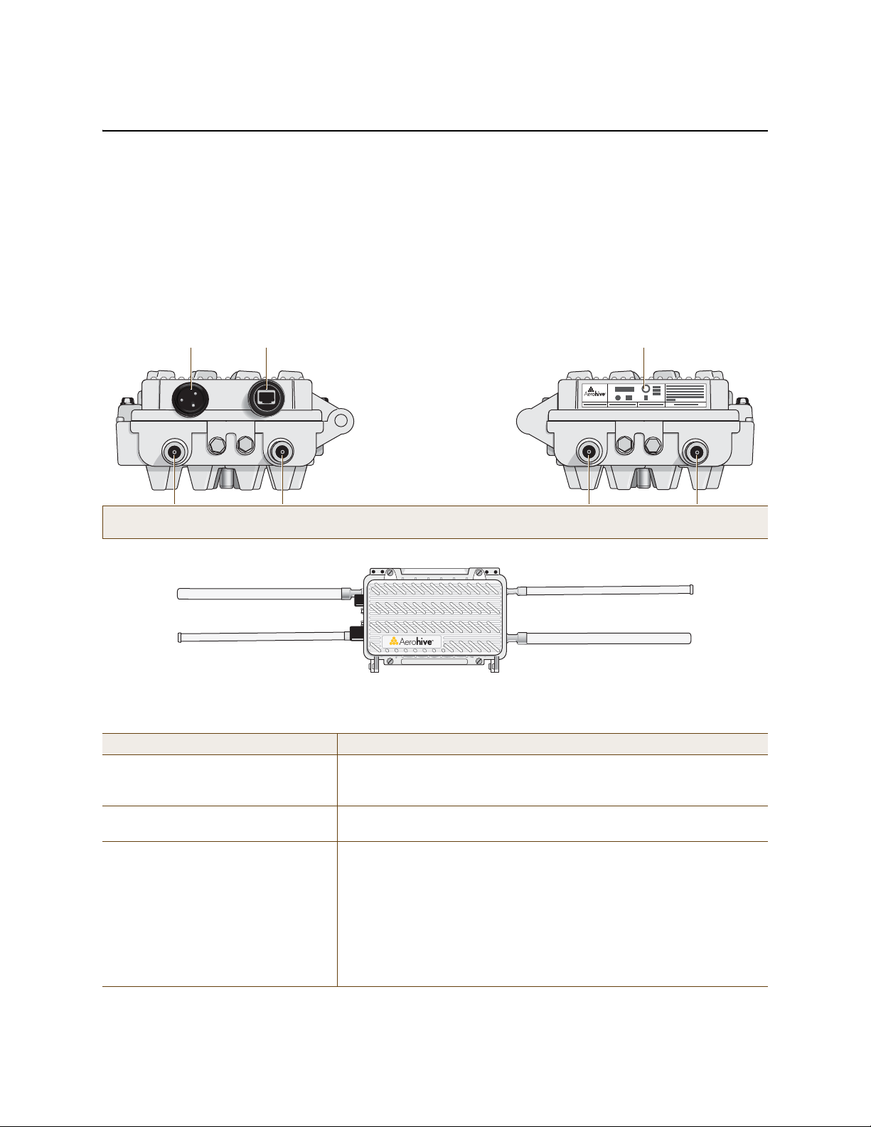
HIVEAP PRODUCT OVERVIEW
The HiveAP 28 is a multi-channel wireless AP (access point) for outdoor use. It is compatible with IEEE 802.11b/g
(2.4 GHz) and IEEE 802.11a (5 GHz) standards and supports a variety of Wi-Fi (wireless fidelity) security protocols,
including WP A (Wi-Fi Protected Access) and WPA2.
You can see the hardware components on the HiveAP 28 in Figure 1. Each component is described in Table 1.
Figure 1 HiveAP 28 Hardware Components
5 GHz 2.4 GHz 5 GHz 2.4 GHz
Table 1 HiveAP 28 Component Descriptions
Component Description
Detachable Single-Band Antennas The two pairs of detachable omnidirectional dipole antennas operate at
two radio frequencies: one pair at 2.4 GHz (for IEEE 802.11b/g) and the
other at 5 GHz (for IEEE 802.11a). For details, see "Antennas" on page 37.
Type N Connectors (Female) Attach antennas to the HiveAP 28 through these connectors. For details,
see "Attaching Antennas" on page 42.
Waterproof Power Connector Using the power connector is one of two methods through which you can
power the HiveAP 28. To connect it to a 100 – 240-volt AC power source,
use the power cable that ships with the product as an extra option.
Because the HiveAP does not have an on/off switch, connecting it to a
power source automatically powers on the device. The power source
must have a readily accessible service disconnect switch incorporate d
into the fixed wiring installation so that you have the ability to turn the
power on and off. (The other method that the HiveAP can obtain power is
through its PoE port.)
34 Aerohive
Page 7

HIVEAP PRODUCT OVERVIEW
2
Compression Nut
End Cap
Gasket
(inside)
Gasket
(squeezed out)
1
3
Slide the Ethernet cable through the two
halves of the waterproof RJ-45 connector
assembly, screw the halves loosely together,
and then plug the cable into the Ethernet port.
Tighten the compression nut
into the Ethernet port housing
on the chassis.
Tighten the end cap until
the gasket is squeezed out
the opening and forms a
watertight seal around the
cable.
Component Description
10/100 Mbps PoE Port The 10/100-Mbps Ethernet port supports IEEE 802.3af PoE (Power over
Ethernet) and receives RJ-45 connectors. The HiveAP can receive its
power through an Ethernet connection to PSE (power sourcing
equipment) that is 802.3af-compatible. (If you connect the HiveAP to a
power source through the power connector and PoE port simultaneously,
the device draws power through the power connector and automatically
disables PoE.)
The HiveAP 28 can also connect to the wired network or to a wired devi ce
(such as a security camera) through this port. It is compatible with
10/100Base-T/TX and automatically negotiates half- and full-duplex
connections with the connecting device. It is autosensing and adjusts to
straight-through and cross-over Ethernet cables auto mati cally
(MDI/MDI-X). It also automatically adjusts for 802.3af Alternative A and B
methods of PoE. For detai ls, see "Ethernet Port".
Ethernet Port
The HiveAP 28 has a 10/100Base-T/TX PoE (P ower over Et hern et) p ort. Its pi n a ssignme nt s follow the TI A/EI A-5 68 -B
standard (see Figure 2 on page 26). The PoE port accepts standard types of Ethernet cable—cat3, cat5, cat5e, or
cat6—and can receive power over this cable from power sourcing equipment (PSE) that is 802.3af-compatible. Such
equipment can be embedded in a switch or router , or it can come from purpose-built devices that inject power into
the Ethernet line en route to the HiveAP. Because the PoE port has autosensing capabilities, the wiring termination
in the Ethernet cable can be either straight-through or cross-over (MDI/MDI-X). For outdoor deployments use
weatherproofed shielded twisted pair (STP) Ethernet cables.
To ensure a waterproof seal for the Ethernet connection, use the RJ-45 connector assembly, which comes in three
parts: a compression nut, end cap, and gasket.
Figure 2 Connecting the Ethernet Cable
1. Insert one end of the Ethernet cable through the waterproof RJ-45 connector assembly and plug the cable into
the Ethernet port.
2. Tighten the compression nut by twisting it clockwise into the Ethernet port housing on the chassis.
3. Tighten the end cap by twisting i t clockwise onto the compression nut and tighten until the rubber gasket
emerges and wrap itself around the Ethernet cable.
The Ethernet connection is now sealed and waterproof.
Deployment Guide 35
Page 8

Chapter 3 The HiveAP 28 Outdoor Platform
4. Connect the other end of the Ethernet cable to PSE (power sourcing equipment), such as a power injector, if the
HiveAP 28 receives power through PoE, or directly to a network device, such as a switch, if it receives power
through a power cord.
Note: To prevent damage to the HiveAP 28 or power injector when using PoE to provide power, connect the
Ethernet cable from the power injector to the HiveAP 28, and connect the injector to a power jack
before applying power.
If the Ethernet cable connects the HiveAP to another device that is indoors, you must install appropriate
lightning protection at the point before it enters the building. Failing to do so might cause damage t o the
equipment as well as serious injury or death.
Note: When the HiveAP acts as a mesh point and does not use the Ethernet port, cover the Ethernet port with a
connector cap to prevent water intrusion and possible safety hazards.
Power Connector
The HiveAP 28 can receive power through an Ethernet cable using PoE or through a power cord. Aerohive
recommends using either PoE or wiring the power cord directly to a 100 – 240-volt AC power source. Only plug the
power cord into an electric outlet when configuring the device before deployment or whe n testing it in the lab.
Note: When the HiveAP receives power through PoE, cover the power connector with a connector cap to prevent
water intrusion and possible safety hazards.
To connect the power cord to the HiveAP 28:
1. Align the slot in the power cord plug with the small tab at the top of the three-pin power connector, and slide
the plug firmly over the pins until it is fully seated in the power connector.
2. Slide the cover over the connector and tighten it by turning the cover clockwise.
3. Install a lightning protector between the HiveAP 28 and its power source.
4. When possible, run the cord through a conduit to protect it from the elements. Where the cord is exposed,
allow enough slack in it to create a drip loop. Leaving some slack in the cord lets water run away from the
connections at each end. Use only a weatherproof power cord, such as the cord that ships with the HiveAP 28.
5. Strip the other end of the power cord and wire it directly to a power source, such as a junction box that has a
service disconnect switch that you can use to turn the power on and off. Also, because the HiveAP 28 does not
have short-circuit (over current) protection built into it, it relies on the protection provided by the power
source to which you connect it. Ensure that the protective device, such as a circuit breaker, is not rated greater
than 15A. Furthermore, if you need to install the HiveAP 28 in a wet or damp location, the AC branch circuit
that is powering it must be provided with ground fault protection (GFCI), as required by Article 210 of the
National Electrical Code (NEC).
Note: The HiveAP 28 must be grounded. Do not operate it unless there is a suitably installed ground
conductor. Contact the appropriate electrical inspection authority or an electrician if you are
uncertain that suitable grounding is available.
36 Aerohive
Page 9

HIVEAP PRODUCT OVERVIEW
Note: To show the shape of radiation more clearly,
this illustration depicts the coverage provided by
only one active antenna and is not drawn to scale.
The omnidirectional antennas
radiate equally in all directions,
forming a toroidal pattern.
HiveAP
The two 802.11b/g antennas link internally to Radio 1
and broadcast in the 2.4 GHz frequency range.
802.11a Main Antenna
802.11b/g Main Antenna
802.11b/g Auxiliary Antenna
802.11a Auxiliary Antenna
The two 802.11a antennas link internally to Radio 2
and broadcast in the 5 GHz frequency range.
Radio 1
RF 802.11b/g
2.4 GHz
Radio 2
RF 802.11a
5 GHz
Antennas
The HiveAP 28 includes two detachable single-band antennas with 8dBi gains (802.11b/g) and two detachable
single-band antennas with 10dBi gains (802.11a). These antennas are omnidirectional, providing fairly equal
coverage in all directions in a toroidal (donut-shaped) pattern around each antenna. When the antennas are
vertically positioned, coverage expands primarily on the horizontal plane, extending horizontally much more than
vertically. See Figure 3, which shows the toroidal pattern emanating from a single vertically positioned antenna.
Note that when high gain antennas are added, the torus shape becomes somewhat elongated or compressed. If the
HiveAP 28 is mounted higher than 20 feet the center of the torus curves inw ard so that the connection quality,
directly underneath the center of the HiveAP 28, becomes compromised.
To change coverage to be more vertical than horizontal, position the HiveAP so that the antennas are on a
horizontal plane. You can also resize the area of coverage by increasing or decreasing the signal strength.
Figure 3 Omnidirectional Radiation Pattern
The pairs of antennas operate concurrently in two different frequency ranges: 2.4 GHz (IEEE 802.11b/g) and 5 GHz
(IEEE 802.11a). Using two different frequency ranges reduces the probability of interference that can occur when
numerous channels operate within the same range. C onceptually, the relationship of antennas and radios is shown in
Figure 4. (For information about attaching the antennas to the HiveAP 28, see "Attach ing Antennas" on page 42.)
Figure 4 Antennas and Radios
\
Note: The HiveAP 20 uses interface interface radio antenna external command to enable an
external antenna attached to it. Entering this command on the HiveAP 28 disables the antenna on the
opposite side of the device from the radio to which the interface is linked and results in a loss of diversity.
Deployment Guide 37
Page 10

Chapter 3 The HiveAP 28 Outdoor Platform
MOUNTING THE HIVEAP 28 AND ATTACHING ANTENNAS
Using the mounting accessories (available separately) you can mount the HiveAP in various locations:
• "Pole Mount" on page 39 – Mount the HiveAP 28 on a pole such as the arm of a street light.
• "Strand Mount" on page 40 – Suspend the HiveAP 28 from a cable or phone line.
• "Surface Mount" on page 41 – Mount the HiveAP 28 on a flat surface such as a wall or beam.
You can mount the HiveAP 28 in any of these locations as long as the object to which you mount it and the attaching
screws can support its weight (9 lbs., 4.08 kg).
After mounting the HiveAP 28, attach the antennas as explained in "Attaching Antennas" on page 42.
Before you mount the HiveAP 28 and attach antennas, read the following warnings and cautions:
• To install the HiveAP 28, you must be a qualified installation professional, licensed or certified in
accordance with local regulations.
• Use lightning arrestors and ground both the HiveAP 28 and any separately mounted antennas.
• Do not connect or disconnect antennas or cables from the HiveAP 28 during periods of lightning activity.
• If you need to place the HiveAP 28 in an explosive environment, such as in an oil re finery, mine, or any
place where there is flammable gas, it must first be encased in an ATEX enclosure.
• To comply with RF (radio frequency) exposure limits, do not place antennas within 6.56 feet (2 meters) of
people.
• Do not locate antennas near overhead power lines or other electric light or power circuits, or where they
can come into contact with such circuits. When installing antennas, take extreme care not to come into
contact with such circuits, which might cause serious injury or death. For proper installation and grounding
of the antenna, refer to national and local electrical codes: NFPA (National Fire Protection Association) 70,
National Electrical Code Article 810 (U.S.); Canadian Electrical Code, Part I, CSA 22.1 and Section 54
(Canada); and if local or national electrical codes are not available, refer to IEC (International
Electrotechnical Commission) 364, Part 1 through 7 (other countries).
• To prevent damage, avoid over-tightening the connectors, nuts, and screws used to mount the antenna and
the antenna itself.
38 Aerohive
Page 11

MOUNTING THE HIVEAP 28 AND ATTACHING ANTENNAS
Note: For clarity, only one post mounting
set is shown in the illustration. You also
need to use a second set to finish mounting
the HiveAP on a pole.
Use the 1/4-20 bolts and split
washers to attach the shorter end of
the L-shaped bracket to holes in the
underside of the HiveAP 28.
Slip the U-bolt around the pole and
thread its ends through the saddle
clamp and L-shaped bracket.
Thread the split washers and
5/16-18 nuts over the ends of the
U-bolt and tighten until the bracket
assembly and device are secured to
the pole.
1
2
3
Pole Mount
To mount the HiveAP 28 to a pole with a 2-inch diameter, you need two sets of the L-shaped brackets, two 2"
U-bolts, saddle clamps, and the nuts, bolts, and washers shown in Figure 5. You also need a wrench to tighten the
nuts and bolts securely.
Figure 5 Attaching the HiveAP 28 to a Pole
Bird’s-Eye View
5/16-18 Nuts
Split Washers
L-Shaped Bracket
Saddle Clamp
Vertical Pole
(2” diameter)
2” U-Bolt
1/4-20 Bolts
and
Split Washers
5 GHz 2.4 GHz
Side view of the
HiveAP 28
mounted to a
street light
1. Align two of the holes in the sh orter end of the b racket w ith two of the hole s in the Hiv eAP, insert the two bolts
through the washers and bracket, and screw them into the holes in the HiveAP 28 chassis, using a wrench to
tighten the bolts so that the bracket is securely attached.
Note: Repeat this step to attach the other bracket to the HiveAP. However, this time, place the long end of
the bracket in the opposite direction of the first one for better stability. For example, if you attached
2. Holding a saddle clamp against the inside of the long end of one of the L-shaped brackets, slip a U-bolt around
3. Thread a split washer and 5/16-18 nut to each end of the U-bolt , and ti ghte n them with a wre nch to secu re th e
Deployment Guide 39
the first bracket with its long end positioned toward the outside edge of the device, install this second
bracket with the long end of the bracket toward the middle.
the pole and thread it through the two holes in the saddle clamp and L-shaped bracket.
Note: One of the holes in the bracket is arc-shaped so that you can adjust the angle of the mounted device if
necessary.
U-bolt firmly to the pole.
Note: Repeat steps 2 and 3 to attach the other U-bolt and saddle clamp to the remaining L-shaped bracket
and secure the HiveAP 28 to the pole.
Page 12

Chapter 3 The HiveAP 28 Outdoor Platform
5 GHz 2.4 GHz
Strand Clamp
Split Washer
Strand
1/4-20 Bolt
End View
Side View
Side view of the
HiveAP 28 mounted
on a cable strand
90-Degree
Type N Adapter
90-Degree
Type N Adapter
2.4 GHz Antennas
Note: For clarity, only one bolt, washer,
and strand clamp are shown in the
illustration on the left. Y ou also need to use
a second set of these items to finish
clamping the HiveAP to a wire strand.
Position the HiveAP 28 so that its
long side is directly beneath a cable
or wire strand.
Place the strand clamps over the
wire, and bolt the clamps tightly to
the chassis around the strand.
1
2
Attach 90-degree type N adapters to the
2.4 GHz antenna connectors so that the
adapters face downward, and then
attach the antennas to the adapters
3
Strand Mount
The HiveAP 28 outdoor platform can also be mounted on a cable or strand of wire as shown in Figure 6. When
mounted on a wire strand, use 90-degree N type adapters (not in cluded) to orient the a ntennas verti cally. If you do
not use the adapters and orient the antennas horizontally, the area covered will be far less.
Figure 6 Clamping the HiveAP 28 to a Wire Strand
To mount the HiveAP 28 on a wire or strand, you need a wrench and two 1/4-20 bolts, split washers, strand clamps,
and 90-degree type N adapters. In the following instructions, you use only the 2.4 GHz antennas.
1. Position the HiveAP 28 so that its long side (with three holes at each end) is underneath a cable or wire strand
running lengthwise along the upper side of the chassis (for the proper orientation, see the inset in Figure 6).
2. Place the strand clamp over the wire and use the 1/4-20 bolt and split washer to se cure the strand between th e
clamp and chassis.
Note: Repeat the preceding steps to fasten the other end of the HiveAP 28 to the cable or wire strand.
3. Attach the 90-degree type N adapters to the two 2.4 GHz antenna connectors and then attach the antennas to
the adapters so that the antennas face downward. For details, see "Attaching Anten nas" on page 42.
40 Aerohive
Page 13

MOUNTING THE HIVEAP 28 AND ATTACHING ANTENNAS
5 GHz 2.4 GHz
7 7/8”
200 mm
Top of Wall
5 GHz 2.4 GHz
Mounting Plate
1/4-20 x 1/2”
Flat Head Screws
Bird’s-Eye View
Side view of the
HiveAP 28 mounted
on an exterior wall
Guide the screws fastened to
the wall through the keyholes
in the mounting plates.
Attach four screws to a secure object
such as a wall or beam. Space them
8 1/8" (206 mm) apart vertically and
7 7/8" (200 mm) apart horizontally.
With the ridged edge of the holes on the
mounting plates facing the HiveAP 28, use
1/4-20 x 1/2 inch screws to secure the two
mounting plates to its underside.
1 2 3
Note: For clarity, only one mounting plate is shown in the illustration.
You also need a second plate with another set of screws.
Surface Mount
You can use the mounting plate to attach the HiveAP 28 to any surface that supports its weight (9 lbs., 4.08 kg), and
to which you can screw or nail the plate. First, mount the plate to the HiveAP 28, and then attach the plate to the
surface, as shown in Figure 7. Note that the screw heads that you attach to the wall or surface must be small
enough for the keyholes on the mounting plate to slip over them.
Note: Because the metal in a wall can degrade the radio signal pattern, Aerohive recommends using sector
antennas instead of omnidirectional antennas when mounting the device on a wall.
Figure 7 Mounting the HiveAP 28 on a Wall
To mount the HiveAP 28 to a surface like a wall, you need two mounting plates, four 1/4-20 x 1/2" flat head screws,
four screws (no bigger than 5/16"), and a screw driver:
1. Align the ridged edge of one of the mounting plates with two of the holes located on the underside of the
HiveAP 28, and use two 1/4-20 x 1/2" flat head screws to secure the plate against the HiveAP 28. Then attach
the other mounting plate to the HiveAP 28 in the same way.
2. Attach four 5/16" screws to a wall or beam. They must be 8 1/8" (206 mm) apart vertically and 7 7/8" (200 mm)
apart horizontally to accommodate the keyholes on the mounting plates.
3. Guide the keyholes over the screws fastened to the wall and pus h downward after the screw heads ha ve cleared
the keyholes.
Deployment Guide 41
Page 14

Chapter 3 The HiveAP 28 Outdoor Platform
Attaching Antennas
You can connect the antennas directly to the HiveAP 28 or mount them separately. Although connecting the
antennas directly to the device typically provides better performance, in some cases the location of the HiveAP
might not be a good location for the antennas; for example, if the HiveAP 28 is mounted on a reinforced concrete
wall that interferes w ith radio coverage. In such cases, mounting the antennas separately in a more open location
can improve coverage; however, bear in mind that cables introduce loss into the overall signal strength and that the
longer the cable connecting the antennas to the HiveAP 28, the greater the loss will be.
Note: Cover any unused antenna connectors with a connector cap to prevent water intrusion and possible safety
hazards.
Connecting Antennas Directly to the HiveAP 28
The two 2.4 GHz and two 5 GHz antennas that ship with the HiveAP 28 have male Type N connectors that you can
connect directly to the female Type N antenna connectors on the HiveAP 28. You can also use self-amalgamating
PTFE (polytetrafluoroethylene) tape, which is available separately from Aerohive, to create a w aterproof seal at the
points of attachment.
To attach the antennas:
1. Remove the antenna connector covers from the HiveAP 28 (you can leave a cover on the connector if you are
not planning to use it), and make sure that the surface of the connectors on the HiveAP 28 and the connectors
on the antennas are clean.
2. If you are using PTFE tape, wrap the tape around the threads on the HiveAP 28 antenna connectors as follows:
2.1. Starting at one end of the threads on one of the connectors, stretch the tape and wrap it in half-lap
layers until you cover the threads completely.
2.2. Wrap the tape in the opposite direction to bring it back onto itself for one full wrap.
2.3. Place one thumb on the tape at the point of termination and stretch the tape until it breaks.
2.4. Repeat the preceding steps to cover all the connectors to which you will attach antennas.
3. Connect the 2.4 GHz antennas to the 2.4 GHz antenna connectors. (To tighten an antenna, turn the antenna
base cap—the textured metal band that encloses the connector—clockwise over the tape-covered threads of the
HiveAP antenna connector.)
Their connections are now sealed and waterproof.
4. Repeat the preceding steps to connect the 5 GHz antennas.
Mounting Antennas Separately
In addition to connecting antennas directly to the HiveAP 28, you can also mount them separately and run a cable
between the antennas and the device. Use either male-to-female cables with Type N connectors or use
male-to-male or female-to-female cables with cable gender changers. (The antennas have male Type N connectors
and the HiveAP 28 has female Type N connectors.)
Note: Using cables to mount antennas separately causes some signal loss and using a cable gender changer can
cause even more. The amount of loss varies from product to product, so refer to the documentation
accompanying the cables and gender changer you use for information. To minimize loss, Aerohive
recommends using LMR400 cables and using the shortest cables possible.
42 Aerohive
Page 15

MOUNTING THE HIVEAP 28 AND ATTACHING ANTENNAS
Attachment Clamp
Base Cap
Antenna
1 3/8”
Bolt
Nut
Use one wrench to hold the nut
in place and the other to tighten
the bolt.
Insert the antenna into the clamp
until it grips the base cap.
Insert the bolt through the attachment
clamp and hold it in place with the nut.
Do not tighten it yet.
1 2 3
With the attachment clamp against one side of the pole,
insert the V-bolt through the two holes in the clamp from
the other side. Then thread washers and nuts over the two
ends of the bolt and tighten them in place with a wrench.
4
Note: Aerohive recommends attaching the antenna near
the top of the pole. If you need to improve the stability of
the mounted antenna, fasten it to the pole with a hose
clamp (included) as shown on the far right.
or
You can mount antennas at the top of a pole as shown in Figure 8 and Figure 9, or to a flat surface. If you must
mount the antenna lower on a pole, the pole must be nonmetallic—such as one made from a hard plastic like PVC
(polyvinyl chloride)—so that it does not distort the signal. Aerohive recommends that antennas be installed away
from power lines and obstructions that can interfere with radio coverage.
For each antenna that you mount, you need an attachment clamp, a 1 3/8" bolt and nut, a V-bolt, two washers and
two nuts, a hose clamp, and two wrenches.
Figure 8 Securing an Antenna to an Attachment Clamp
1. Insert the 1 3/8" bolt through the attachment clamp and screw a nut loosely onto its end.
2. Place the antenna base cap inside the attachment clamp.
3. Using a pair of wrenches, tighten the nut to the bolt until the clamp grips the base cap firmly.
Figure 9 Mounting an Antenna to a Pole
Side View
Bird’s-Eye View
Antenna
Nuts
Washers
Attachment Clamp
Nonmetallic Pole
(2” diameter)
Hose Clamp
Deployment Guide 43
V-Bolt
Page 16

Chapter 3 The HiveAP 28 Outdoor Platform
4. To mount the antenna on a nonmetallic pole, place the attachment clamp against the pole, thread the V-bolt
through the holes on the attachment, the washers, and nuts, and use the wrenches to tighten the nuts to the
bolt. (Optional) For added stability, fasten the top of the antenna to the pole with the hose clamp.
To mount the antenna directly to a flat surface, run bolts or screws (not included) through the two holes in the
attachment clamp, and fasten them firmly to the surface.
Note: Radio coverage might be limited if the surface acts as an obstruction.
5. Make sure that all the antenna and cable connectors are clean. If you are using PTFE tape, wrap the ta pe around
the threads on the HiveAP 28 antenna connectors as explained in "Connecting Antennas Directly to the HiveAP
28" on page 42.
6. Assuming that you are using male-to-female cables, connect the female Type N connector on the cables to the
male connectors on the antennas.
7. Connect the male Type N connectors on the cables to the female antenna connectors on the HiveAP 28.
DEVICE, POWER, AND ENVIRONMENTAL SPECIFICATIONS
Understanding the range of specifications for the HiveAP is necessary for optimal deployment and device operation.
The following specifications describe the physical features and hardware components, the power adapter and PoE
(Power over Ethernet) electrical requirements, and the temperature and humidity ranges in which the device can
operate.
Device Specifications
• Chassis dimensions: 13 13/16" W x 4 3/8" H x 8 3/8" D (35 cm W x 11 cm H x 21 cm D)
• Weight: (9 lbs., 4.08 kg)
• Antennas: Two detachable single-band 8dBi 802.11b/g antennas and two detachable single-band 10dBi 802.11a
antennas
• Maximum Transmission Power: 20 dBm
• Ethernet port: autosensing 10/100Base-T/TX Mbps, with IEEE 8 02.3af-compliant PoE (Power over Ethernet)
Power Specifications
• AC/DC power adapter:
• Input:100 – 240 VAC
• Output: 17 watts
• PoE nominal input voltages: 48 V, 0.35A
• RJ-45 power input pins: Wires 4, 5, 7, 8 or 1, 2, 3, 6
Environmental Specifications
• Operating temperature: -40 to 140 degrees F (-40 to 60 degrees C)
• Storage temperature: -40 to 194 degrees F (-40 to 90 degrees C)
• Relative Humidity: Maximum 100%
44 Aerohive
Page 17

Chapter 3 The HiveAP 28 Outdoor Platform
Table 2 Maximum allowed conducted output power for specified antennas.
45 Aerohive
802.11b RF (8dBi Omnidirectional, Model : S2406BFNM)
Frequency 2412MHz 2437MHz 2462MHz
Peak Power Output (dBm) 14.20 14.00 14.20
802.11g (8dBi Omnidirectional, Model : S2406BFNM)
Frequency 2412MHz 2437MHz 2462MHz
Peak Power Output (dBm) 16.20 16.80 15.00
802.11a (10dBi Omnidirectional, Model : S4908WBF)
Frequency 5745MHz 5785MHz 5825MHz
Peak Power Output (dBm) 17.80 17.40 17.60
 Loading...