

Aeroflex UTMC UT54ACTS169, UT54ACS169 Datasheet
119 RadHard MSI Logic
UT54ACS169/UT54ACTS169
Radiation-Hardened
4-Bit Up-Down Binary Counters
FEATURES
Fully synchronous operation for counting and programming
Internal look-ahead for fast counting
Carry output for n-bit cascading
Fully independent clock circuit
radiation-hardened CMOS
- Latchup immune
High speed
Low power consumption
Single 5 volt supply
Available QML Q or V processes
Flexible package
- 16-pin DIP
- 16-lead flatpack
DESCRIPTION
The UT54ACS169 and the UT54ACTS169 are synchronous 4bit binary counters that feature an internal carry look-ahead for
cascading in high-speed counting applications. Synchronous
operation is provided by having all flip-flops clocked simultaneously so that the outputs change coincident with each other
when instructed by the count-enable inputs and internal gating.
Synchronous operation helps eliminate the output counting
spikes that are normally associated with asynchronous (ripple
clock) counters. The clock input triggers the four flip-flops on
the rising (positive-going) edge of the clock.
The counters are fully programmable (i.e., the outputs may each
be preset high or low). The load input circuitry allows loading
with the carry-enable output of cascaded counters. Loading is
synchronous; applying a low level at the load input disables the
counter and causes the outputs to agree with the data inputs after
the next clock pulse.
The carry look-ahead circuitry provides for cascaded counters
for n-bit synchronous application without additional gating. Instrumental in accomplishing this function are two count-enable
inputs and a carry output. Assert both count enable inputs (ENP
and ENT) to count. The direction of the count is determined by
the level of the U/D input. When U/D is high, the counter counts
up; when low, it counts down. Input ENT is fed forward to
enable the carry output. The ripple carry output
RCO enables a low-level pulse while the count is zero (all inputs
low) counting down or maximum (15) counting up. The lowlevel overflow carry pulse can be used to enable successive cascaded stages.
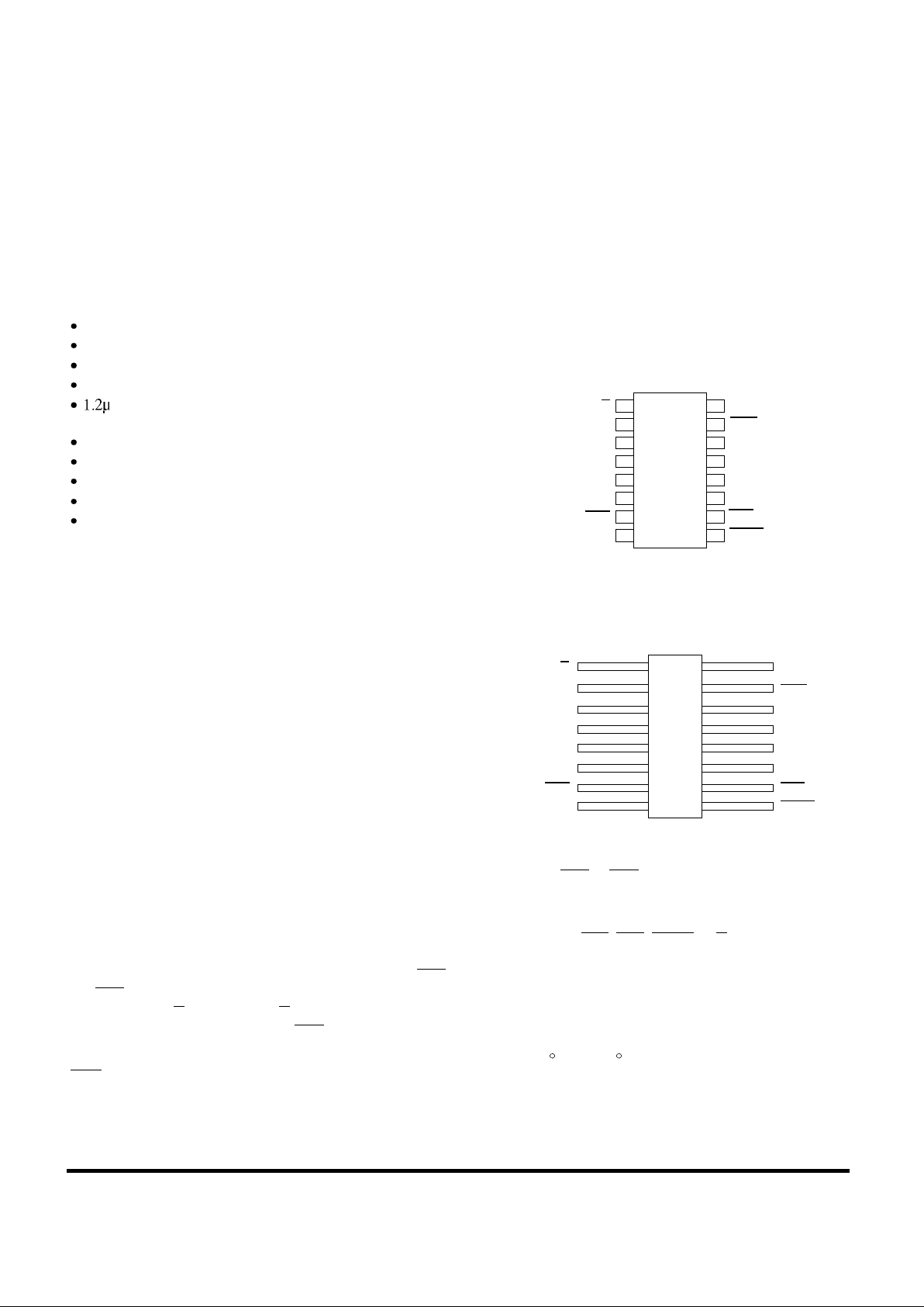
PINOUTS
16-Pin DIP
Top View
16-Lead Flatpack
Top View
Transitions at ENP or ENT are allowed regardless of the level
of the clock input.
The counters feature a fully independent clock circuit. Changes
at control inputs (ENP, ENT, LOAD, U/D) that modify the operating mode have no effect on the contents of the counter until
clocking occurs. The function of the counter (whether enabled,
disabled, loading, or counting) will be dictated solely by the
conditions meeting the stable setup and hold times.
The devices are characterized over full military temperature
range of -55 C to +125 C.
1
2
3
4
5
7
6
16
15
14
13
12
10
11
U/D
CLK
A
B
C
D
ENP
V
DD
RCO
Q
A
Q
B
Q
C
ENT
8 9V
SS
LOAD
Q
D
1
2
3
4
5
7
6
16
15
14
13
12
10
11
V
DD
8
9
U/D
CLK
A
B
C
D
ENP
RCO
Q
A
Q
B
Q
C
Q
D
ENT
V
SS
LOAD

RadHard MSI Logic 120
UT54ACS169/UT54ACTS169
LOGIC SYMBOL FUNCTION TABLE
(9)
LOAD
(1)
U/D M3 (UP)
M1 (LOAD)
CTRDIV 16
(10)
ENT
G5
(7)
ENP G6
(2)
CLK
(3)
A
(4)
B
(5)
C
(6)
D
(15)
RCO
(14)
Q
A
(11)
Q
D
M4 (DOWN)
2,3,5,6+/C7
(12)
Q
C
(13)
Q
B
1,7D
(1)
(2)
(4)
(8)
3,5CT = 15
M2 (COUNT)
2,3,5,6-
4,5CT = 0
Note:
1. Logic symbol in accordance with ANSI/IEEE Std 91-1984 and IEC
Publication 617-12.
OUTPUT LOAD
ENP ENT
U/D CLK
Count Up H L L H
Count Down H L L L
Load Preset L X X X
Inhibit H
H
H
X
X
H
X
X
X
X
 Loading...