

Aeroflex UTMC UT54ACTS163, UT54ACS163 Datasheet
101 RadHard MSI Logic
UT54ACS163/UT54ACTS163
Radiation-Hardened
4-Bit Synchronous Counters
FEATURES
Internal look-ahead for fast counting
Carry output for n-bit cascading
Synchronous counting
Synchronously programmable
radiation-hardened CMOS
- Latchup immune
High speed
Low power consumption
Single 5 volt supply
Available QML Q or V processes
Flexible package
- 16-pin DIP
- 16-lead flatpack
DESCRIPTION
The UT54ACS163 and the UT54ACTS163 are synchronous
presettable 4-bit binary counters that feature internal carry lookahead logic for high-speed counting designs. Synchronous operation occurs by having all flip-flops clocked simultaneously
so that the outputs change coincident with each other when instructed by the count-enable inputs and internal gating. A buffered clock input triggers the four flip-flops on the rising (positive-going) edge of the clock input waveform.
The counters are fully programmable (i.e., they may be preset
to any number between 0 and 15). Presetting is synchronous;
applying a low level at the load input disables the counter and
causes the outputs to agree with the load data after the next clock
pulse.
The clear function is synchronous and a low level at the clear
input sets all four of the flip-flop outputs low after the next clock
pulse. This synchronous clear allows the count length to be modified by decoding the Q outputs for the maximum count desired.
The counters feature a fully independent clock circuit. Changes
at control inputs (ENP, ENT, or LOAD) that modify the operating mode have no effect on the contents of the counter until
clocking occurs. The function of the counter (whether enabled,
disabled, loading, or counting) will be dictated solely by the
conditions meeting the stable setup and hold times.
The devices are characterized over full military temperature
range of -55 C to +125 C.
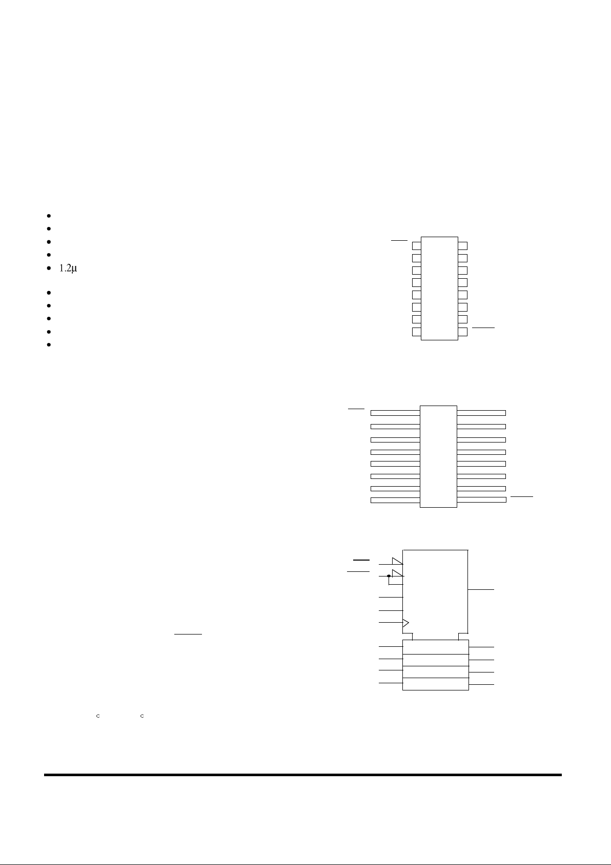
PINOUTS
16-Pin DIP
Top View
16-Lead Flatpack
Top View
LOGIC SYMBOL
1
2
3
4
5
7
6
16
15
14
13
12
10
11
CLR
CLK
A
B
C
D
ENP
V
DD
RCO
Q
A
Q
B
Q
C
Q
D
ENT
8 9V
SS
LOAD
1
2
3
4
5
7
6
16
15
14
13
12
10
11
V
DD
8 9
CLR
CLK
A
B
C
D
ENP
RCO
Q
A
Q
B
Q
C
Q
D
ENT
V
SS
LOAD
(1)
CLR
(9)
LOAD M1
5CT=0
CTRDIV 16
(10)
ENT
G3
(7)
ENP G4
(2)
CLK
(3)
A
(4)
B
(5)
C
(6)
D
(15)
RCO
(14)
Q
A
(11)
Q
D
M2
C5/2,3,4+
(12)
Q
C
(13)
Q
B
1,5D
(1)
(2)
(4)
(8)
3CT = 15
Note:
1. Logic symbol in accordance with ANSI/IEEE Std 91-1984 and IEC Publication 617-12.
RadHard MSI Logic 102
UT54ACS163/UT54ACTS163
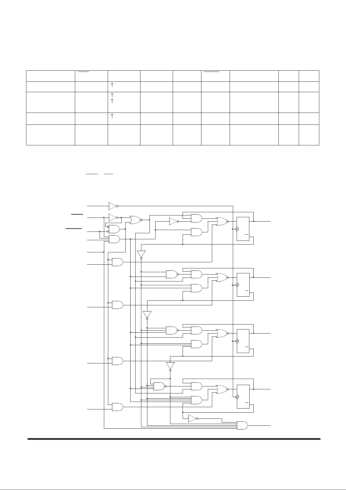
FUNCTION TABLE
H = High voltage level h = High voltage level one setup time prior to the low-to-high clock transition
L = Low voltage level l = Low voltage level one setup time prior to the low-to-high clock transition
Notes:
1. The RCO output is high when ENT is high and the counter is at terminal count HHHH.
2. The high-to-low transition of ENP or ENT should only occur while CLK is high for conventional operations.
3. The low-to-high transition of LOAD or CLR should only occur while CLK is high for conventional operations.
LOGIC DIAGRAM
Operating Mode CLR CLK ENP ENT LOAD DATA A,B,C,D Q
N
RCO
Reset (Clear) l X X X X L L
Parallel Load
h
3
h
3
X
X
X
X
l
l
l
h
L
H
L
1
Count
h
3
h h h X Count
1
Inhibit
h
3
h
3
X
X
l 2
X
X
l
2
h
3
h
3
X
X
Q
N
Q
N
1
L
(2)
(1)
(9)
(7)
(10)
(3)
(4)
(5)
(6)
(14)
(12)
(13)
(11)
(15)
Q
A
Q
B
Q
C
Q
D
RCO
DATA D
DATA C
DATA B
DATA A
ENT
ENP
LOAD
CLR
CLK
C
D
Q
Q
C
D
Q
Q
C
D
Q
Q
C
D
Q
Q
 Loading...