

Aeroflex UTMC UT54ACTS74, UT54ACS74 Datasheet
UT54ACS74/UT54ACTS74
Radiation-Hardened
Dual D Flip-Flops with Clear & Preset
FEATURES
• radiation-hardened CMOS
- Latchup immune
• High speed
• Low power consumption
• Single 5 volt supply
• Available QML Q or V processes
• Flexible package
- 14-pin DIP
- 14-lead flatpack
DESCRIPTION
The UT54ACS74 and the UT54ACTS74 contain two independent D-type positive triggered flip-flops. A low level at the
Preset or Clear inputs sets or resets the outputs regardless of the
levels of the other inputs. When Preset and Clear are inactive
(high), data at the D input meeting the setup time requirement
is transferred to the outputs on the positive-going edge of the
clock pulse. Following the hold time interval, data at the D
input may be changed without affecting the levels at the outputs.
The devices are characterized over full military temperature
range of -55 C to +125 C.
FUNCTION TABLE
INPUTS OUTPUT
PRE CLR CLK D Q Q
L H X X H L
H L X X L H
L L X X
H H H H L
H H L L H
H H L X Q
Note:
1. The output levels in this configuration are not guaranteed to meet the minimum levels for VOH if the lows at preset and clear are near VIL maximum.
In addition, this configuration is nonstable; that is, it will not persist when
either preset or clear returns to its inactive (high) level.
H
1
o
H
1
Q
o
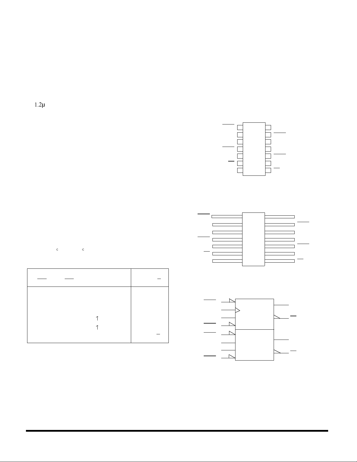
PINOUTS
14-Pin DIP
Top View
CLR1
CLK1
PRE1
V
D1
Q1
Q1
SS
1
14
V
DD
2
13
CLR2
3
12
D2
4
11
CLK2
5
10
PRE2
6
9
Q2
7
8
Q2
14-Lead Flatpack
Top View
CLR1
D1
CLK1
PRE1
Q1
Q1
V
SS
14
2
13
3
12
4
11
5
10
6
9
7
8
V
DD
CLR2
D2
CLK2
PRE2
Q2
Q2
1
LOGIC SYMBOL
(4)
PRE1
(3)
CLK1
(2)
D1
(1)
CLR1
(10)
PRE2
(11)
CLK2
(12)
D2
(13)
CLR2
Note:
1. Logic symbol in accordance with ANSI/IEEE standard 91-1984 and IEC
Publication 617-12.
S
D1
R
C1
(5)
(6)
(9)
(8)
Q1
Q1
Q2
Q2
45 RadHard MSI Logic
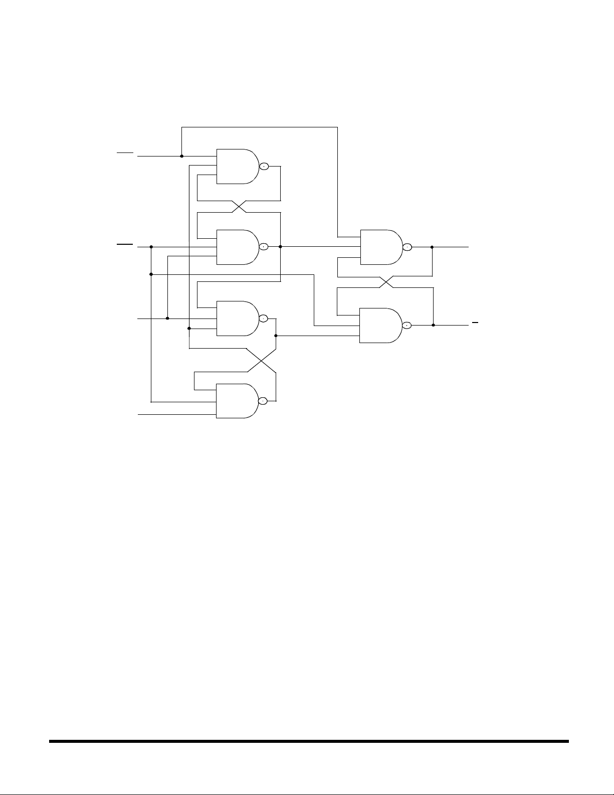
LOGIC DIAGRAM
PRE
UT54ACS74/UT54ACTS74
CLR
CLK
D
Q
Q
RadHard MSI Logic 46
 Loading...