

Page 1
Practical Low Resistance Measurements
Raytheon Aircraft Company
Bob Nuckolls
Sr. Engineer/SME
Wichita, Kansas
Modern digital multimeters have two important
limitations:
(1) When taking resistance readings on switch or relay
contacts, the common multimeter often produces high,
almost meaningless resistance readings due to very low test
currents generated within the instrument: A sampling of
resistance measurement currents for five different digital
instruments showed no current exceeding 1.5 milliamperes.
Most measurements were are made at
currents on the order of 250 microamperes.
(2) Typical off-the-shelf multimeters offer
a low resistance measurement on the order
of 200 ohms full scale with a resolution of
0.1 ohms. For qualitative measurements of
components like switches and relay
contacts the technician needs to resolve
resistance values of 1 ohm or less with
resolution in the milliohms. Contact
resistance due to film or corrosion build-up
requires a substantial current flow to
penetrate contact film.
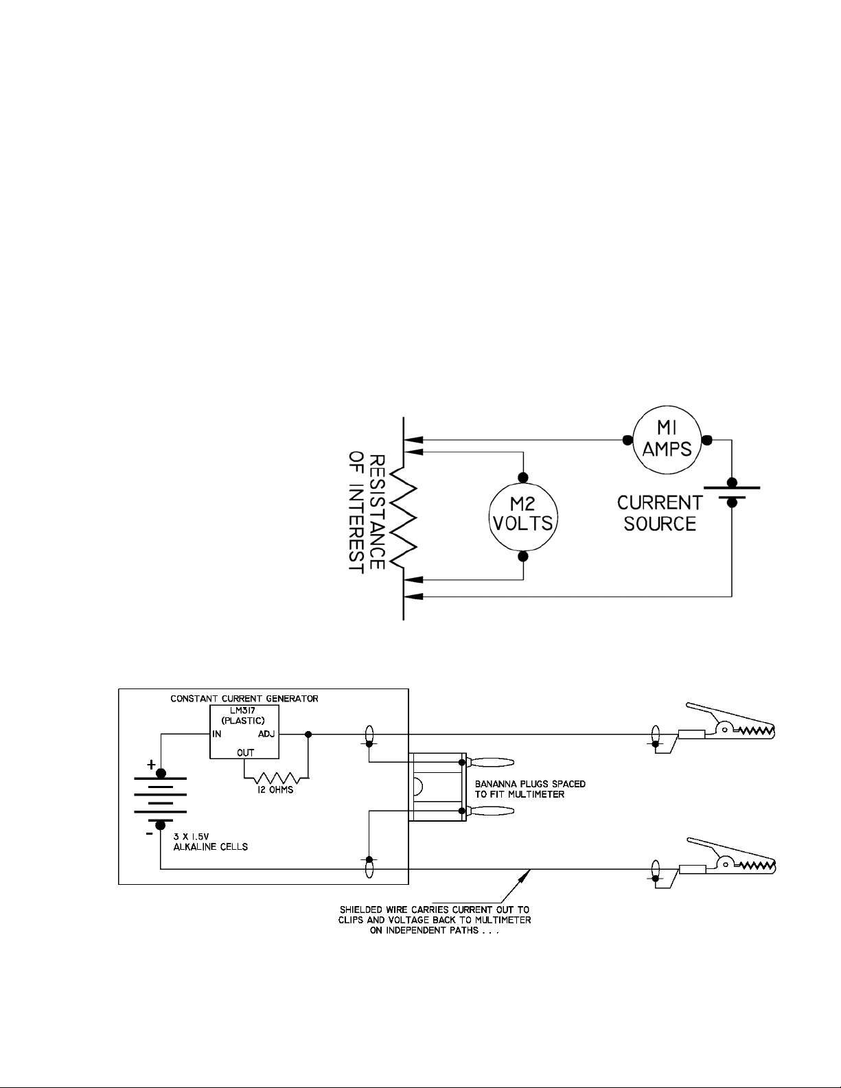
A “4-wire” measurement technique for low
resistance is illustrated in Figure 1. A
current of known value is caused to run
through the resistor of interest. A voltmeter is used to
measure drop across the resistor INSIDE the current
connections. Ohms law is used to calculate the resistance
value. This technique eliminates effects of test equipment
lead and probe resistance.
A practical implementation of the 4-wire measurement
technique illustrated in Figure 2. can be assembled in an
hour or so with a bill of materials under $10. The outer
housing is a plastic project box from Radio Shack. Dual
Figure 1. Basic 4-Wire Ohmmeter Technique
Figure 2. Schematic Diagram - Low Resistance Measurement Adapter
Page 1 of 3
Page 2

banana plugs to fit most
multimeters along with
components to implement a
constant current source are
readily available from suppliers
of commercial components such
as Radio Shack, Digikey,
Hosfelt, Jameco and others
Construction Notes
A constant current generator is
fabricated from a popular
adjustable voltage regulator
combined with a 12-ohm
resistor. The LM317 (Figure 4)
is readily available in the TO220 plastic package from most
parts suppliers. The LM317
series, 3-terminal regulators
come in a variety of packages
and environmental ratings. Any
version is suited to this
application.
Power to bias the test comes
from three AA sized alkaline
cells in series. Spring loaded
battery holders have a potential for poor connection to the
cells with age and environmental effects. Soldered
connections are easy to make and very reliable
Brighten an area on the
battery to be soldered
with a file, knife edge
or edge of grinding
wheel. The Dremel
Moto-Tool with a cutoff wheel attached
works really nice. Use a
hot iron to get on and
off quickly each time
the cell is touched.
First, tin the area where
a wire will attach to the
cell. Tin the wire and
then tack it into place
on the cell.
With a little practice,
the two times you touch
Figure 4. LM317 Connections.
less than two or three seconds total. Eliminating the battery
holder allows construction to be contained in a smaller
enclosure and eliminates future problems that arise from
poor contact with cells.
the cell with the
soldering iron should be
Figure 3. Interior View Component Location
Calibration
The finished fixture can be tested for calibration by
plugging it into the multimeter while it is set up to measure
current. The fixture fabricated for this article produces a
constant current of 104 mA. This is expected; the LM317
voltage regulator is a 1.25 volt device. A 12.0 ohm resistor
would be expected to produce a current slightly higher than
100 mA. For most purposes, this variability is insignificant.
Using the Fixture
The adapter illustrated herein generates 100 milliamperes
of test current. When used in conjunction with a multimeter
having readout in tenths of a millivolt, the resolution of a
low resistance measurement will be 1 milliohm.
This device will yield useful resistance measurements up to
better than 10 ohms (1.000 volts displayed on multimeter)
If your multimeter has a 200 or 300 millivolt range, a 100
milliampere test adapter will display 2 or 3 ohms full scale.
The low resistance measurement adapter is useful in
diagnosing system malfunctions that could be attributed to
increased contact resistance in switches or relays. Switches
outside the pressure vessel on turbojet aircraft are
particularly good candidates for environmental effects,
Page 2 of 3
Page 3

especially those under the nacelles or on
landing gear struts.
When investigating the condition of a switch
or relay, it’s useful to exercise the part and
observe variations in contact resistance from
one measurement to the next. Unless you are
offered baseline resistance values as part of a
published test procedure, you’ll have to make
comparative measurements between a
suspected bad and a known good component.
Storage
Current flows from these cells only while a
measurement is being made. Shelf life of an
alkaline cell is 5 years or more. Cells in this
fixture should not require frequent
replacement. To take advantage of the very
long shelf life of alkaline cells, be sure to store
the adapter in a way that protects the lead
wires and/or exposed banana plugs from
becoming shorted together.
Figure 6. Adapter Shows 2 Milliohms Parasitic Resistance.
Page 3 of 3
Page 4

Page 5

Page 6

 Loading...