

AeroComm PKLR2400-200 Users Manual
AC5124
AC5124
AC5124AC5124
2.4 GHz OEM TRANSCEIVER
2.4 GHz OEM TRANSCEIVER
2.4 GHz OEM TRANSCEIVER2.4 GHz OEM TRANSCEIVER
Specifications Subject to Change
Specifications Subject to Change
Specifications Subject to ChangeSpecifications Subject to Change
User’s Manual
User’s Manual
User’s ManualUser’s Manual
Version 4.4
Version 4.4
Version 4.4Version 4.4
10981 EICHER DRIVE
10981 EICHER DRIVE
10981 EICHER DRIVE10981 EICHER DRIVE
LENEXA, KS 66219
LENEXA, KS 66219
LENEXA, KS 66219LENEXA, KS 66219
(800) 492-2320
(800) 492-2320
(800) 492-2320(800) 492-2320
www.aerocomm.com
www.aerocomm.com
www.aerocomm.comwww.aerocomm.com
wireless@aerocomm.com
wireless@aerocomm.com
wireless@aerocomm.comwireless@aerocomm.com

DOCUMENT INFORMATION
DOCUMENT INFORMATION
DOCUMENT INFORMATIONDOCUMENT INFORMATION
Copyright
Copyright
CopyrightCopyright
Information
Information
InformationInformation
This material is preliminary
This material is preliminary
This material is preliminaryThis material is preliminary
Information furnished by A
EROCOMM
by A
are covered by the warranty and patent indemnification provisions appearing in its
Terms of Sale only. A
Copyright © 2000 A
The information contained in this manual and the accompanying
software programs are copyrighted and all rights are reserved by
A
EROCOMM
periodic modifications of this product without obligation to notify
any person or entity of such revision. Copying, duplicating, selling, or otherwise
distributing any part of this product without the prior consent of an authorized
representative of A
All brands and product names in this publication are registered
trademarks or trademarks of their respective holders.
EROCOMM
, Inc. A
EROCOMM
makes no warranty, express, statutory, and implied or by
EROCOMM
EROCOMM
EROCOMM
in this specification is believed to be accurate. Devices sold
description, regarding the information set forth herein. A
, Inc. All rights reserved.
, Inc. reserves the right to make
, Inc. is prohibited.
EROCOMM
reserves the right to change
specifications at any time and without notice.
EROCOMM
A
’s products are intended for use in normal commercial applications. Applications
requiring extended temperature range or unusual environmental requirements such as military,
medical life-support or life-sustaining equipment are specifically not recommended without
additional testing for such application.
11/24/03 2

DOCUMENT INFORMATION
DOCUMENT INFORMATION
DOCUMENT INFORMATIONDOCUMENT INFORMATION
Revision
Revision Description
RevisionRevision
Version 3.6 Remove SDK developer kit information – 6/6/00
Version 3.7 6/28/00 – Made data rates uniform at 882 Kbps
Version 3.8 8/18/00 – Changed Input Voltage tolerance from 5% to 2%
Version 3.9 9/25/00 – Corrected DTR pin number from 33 to 34, Pin 33 is NC
Version 4.2 10/25/01 - Changed PKLR2400S part number to AC5124C
Version 4.3 3/25/01 – Changed Interface Timeout values in Table 6, EEPROM Parameters
Version 4.4 11/24/03 – Updated all references to operating temperature from 0°C to 60°C to -40°C to
Description
DescriptionDescription
Re-arrange the layout of the specification to ease use
Correct Channels from 75 to 77 and provide range in Hex, Section 5.1.3
Reformat I/O table to view additional line descriptions
Changed temperature from 0 – 60 °C to 0 – 70 °C
Changed Baud Low Default from F7 to F1
Updated Section 6 – API Command Set with examples & corrections
Added pin notations on Figure 1 - Mechanical Overview of AC5124C
Changed Pin 24 from Reserved to NC
Remove Note from the CTS timing diagram in Sections 3.3.1 & 4.6
Changed description for Diagnostic Result command in Section 6.1.3
Added AC5124C-200 information
Added Section 3.3, Electrical Specifications
Added RSSI calibration steps in Section 3.2.1
Added Section 4.6, Addressed & Broadcast Communication
Added Section 4.7, Handshaking
Updated Table 6, EEPROM Parameters to include new parameters
Updated Section 5, API Command Set to include command examples
Updated Section 6, Configuring the AC5124C to include new parameter definitions
Added Section 7, Initializing the AC5124C Transceiver
Updated Section 8, Mechanical Overview to include new drawings
Updated RF Mode 1 (EEPROM Address 4Ch) to include new definition for Bit 7
Added Section 6.1.15.5, Mixed Mode
Updated Approved Antenna List
80°C. All AC5124 products are industrial temperature. Added AT Commands for
reading and writing the EEPROM. Updated RSSI plot for new receiver IC.
11/24/03 3
FCC INFORMATION
FCC INFORMATION
FCC INFORMATIONFCC INFORMATION
Agency Approval Overview
Agency Approval Overview
Agency Approval OverviewAgency Approval Overview
Part Number
Part Number US/FCC
Part NumberPart Number
AC5124-10 X X X X X
AC5124-200 X X X-20cm*
* See RF Exposure warning on page 6
** Does not include France and Spain
Note: The product approvals above are with antennas specified on page 5.
Agency Identification Numbers
Agency Identification Numbers
Agency Identification NumbersAgency Identification Numbers
Part Number
Part Number US/FCC
Part NumberPart Number
AC5124-10 KQL-PKLR2400 CAN2268391158A X
AC5124-200 KQL-PKLR2400-200 CAN2268391180A
FCC Notice
FCC Notice
FCC NoticeFCC Notice
WARNING:
WARNING: This device complies with Part 15 of the FCC Rules. Operation is subject to the
WARNING: WARNING:
following two conditions: (1) This device may not cause harmful interference
and (2) This device must accept any interference received, including
interference that may cause undesired operation.
US/FCC CAN/IC
US/FCCUS/FCC
US/FCC CAN/IC
US/FCCUS/FCC
CAN/IC EUR/EN**
CAN/ICCAN/IC
EUR/EN** Portable
EUR/EN**EUR/EN**
CAN/IC EUR/EN
CAN/ICCAN/IC
Portable Mobile
PortablePortable
EUR/EN
EUR/ENEUR/EN
Mobile
MobileMobile
Antenna Warning
Antenna Warning
Antenna WarningAntenna Warning
WARNING:
WARNING: This device has been tested with an MMCX connector with the antennas listed
WARNING: WARNING:
below. When integrated in the OEMs product, these fixed antennas require
installation preventing end-users from replacing them with non-approved
antennas. Any antenna not in the following table must be tested to comply with
FCC Section 15.203 for unique antenna connectors and Section 15.247 for
emissions.
11/24/03 4

FCC INFORMATION
FCC INFORMATION
FCC INFORMATIONFCC INFORMATION
Approved Antenna List
Approved Antenna List
Approved Antenna ListApproved Antenna List
AC5124-10
AC5124-10AC5124-10
AC5124-10
AC5124-10A
AC5124-10AAC5124-10A
AC5124-10A
Item
Item Part Number
Part Number Manufacturer
ItemItem
Part NumberPart Number
1 WCP-2400-MMCX Centurion 2 PM M
2 WCR-2400-SMRP Centurion 2 PM
3 MFB24008RPN Maxrad 8 PM
4 BMMG24000MSMARP12’ Maxrad 1 PM
5 BMMG24005MSMARP12’ Maxrad 5 PM
6 MP24013TMSMARP12 Maxrad 13 M
7 MUF24005M174MSMARP12 Maxrad 5 PM
8 MC2400 Maxrad 2.5 M
9 NZH2400-MMCX (External) AeroComm 1 PM M
10 NZH2400-I (Integrated) AeroComm 1 PM
11 S131CL-5-RMM-2450S Nearson 2 M
12 S181FL-5-RMM-2450S Nearson 2 PM M
13 S191FL-5-RMM-2450S Nearson 3 PM M
14 S151FL-5-RMM-2450S Nearson 5 PM M
15 MLPV1700 Maxrad 4 PM M
Manufacturer Gain (dBi)
ManufacturerManufacturer
Gain (dBi)
Gain (dBi)Gain (dBi)
AC5124-200
AC5124-200AC5124-200
AC5124-200
AC5124-200A
AC5124-200AAC5124-200A
AC5124-200A
M
P=Portable, M=Mobile
P=Portable, M=Mobile
P=Portable, M=MobileP=Portable, M=Mobile
11/24/03 5

FCC INFORMATION
FCC INFORMATION
FCC INFORMATIONFCC INFORMATION
Labeling Requirements
Labeling Requirements
Labeling RequirementsLabeling Requirements
WARNING:
WARNING: The Original Equipment Manufacturer (OEM) must ensure that FCC labeling
WARNING: WARNING:
requirements are met. This includes a clearly visible label on the outside of the
OEM enclosure specifying the appropriate AeroComm FCC identifier for this
product as well as the FCC Notice above. The FCC identifiers are listed above
in the Agency Identifier Numbers section.
RF Exposure AC5124-10
RF Exposure AC5124-10
RF Exposure AC5124-10RF Exposure AC5124-10
WARNING:
WARNING: This equipment has been approved for portable applications where the
WARNING: WARNING:
equipment can be used in direct contact with the human body. Excessive RF
exposure should be avoided.
The preceding statement must be included as a CAUTION statement in
manuals for products operating with Antennas 3, 4, 5, 6, 7, 14 and 15 in the
previous table to alert users on FCC RF Exposure compliance.
RF Exposure AC5124-200
RF Exposure AC5124-200
RF Exposure AC5124-200RF Exposure AC5124-200
WARNING:
WARNING: To satisfy FCC RF exposure requirements for mobile and base station
WARNING: WARNING:
transmitting devices, a separation distance of 20cm or more should be
maintained between the antenna of this device and persons during operation.
To ensure compliance, operations at closer than this distance is not
recommended.
The preceding statement must be included as a CAUTION statement in
manuals for OEM products to alert users on FCC RF Exposure compliance.
11/24/03 6

TABLE OF CONTENTS
TABLE OF CONTENTS
TABLE OF CONTENTSTABLE OF CONTENTS
TABLES......................................................................................................................................................... 8
1. OVERVIEW........................................................................................................................................ 10
2. AC5124 SPECIFICATIONS..............................................................................................................11
3. THEORY OF OPERATION..............................................................................................................12
1.1 D
1.2 I
EFINITIONS
NTERFACE SIGNAL DEFINITIONS
.................................................................................................................................. 12
................................................................................................... 13
1.2.1 Received Signal Strength Indicator (RSSI)...........................................................................14
1.1.2 In Range (IN_RANGE)..........................................................................................................15
1.1.3 Baud Rate Selector (BDSEL)................................................................................................ 15
1.1.4 Microprocessor Reset (µP_RESET)...................................................................................... 15
1.1.5 EEPROM Write Enable (WR_ENA)...................................................................................... 15
1.3 E
LECTRICAL SPECIFICATIONS
......................................................................................................... 16
4. SERIAL INTERFACE MODES........................................................................................................17
4.1 S
4.2 S
4.3 S
4.4 S
4.5 S
4.6 A
ERIAL INTERFACE MODE
ERIAL INTERFACE MODE
ERIAL INTERFACE MODE
ERIAL INTERFACE MODE
ERIAL INTERFACE BUFFER
DDRESSED
ROADCAST COMMUNICATION
& B
01 – T
02 – T
RANSPARENT
RANSPARENT
IXED PACKET LENGTH, WITH TIMEOUT
, F
ND CHARACTER
, E
................................................ 17
............. 17
03 – API .............................................................................................. 18
04 – T
RANSPARENT
IXED PACKET LENGTH, NO TIMEOUT
, F
................ 18
........................................................................................................... 18
.............................................................................. 18
4.6.1 Addressed Mode.................................................................................................................... 19
4.6.2 Broadcast Mode.................................................................................................................... 20
4.7 H
ANDSHAKING
............................................................................................................................... 20
4.7.1 CTS Handshaking ................................................................................................................. 20
4.7.2 RTS Handshaking..................................................................................................................21
4.7.3 Modem Handshaking............................................................................................................21
5. API COMMAND SET........................................................................................................................ 22
5.1 S
YSTEM COMMAND SET
................................................................................................................ 23
5.1.1 Reset..................................................................................................................... ................. 23
5.1.2 Control.................................................................................................................................. 24
5.1.3 Diagnostic Result.................................................................................................................. 24
5.1.4 Standby.................................................................................................................................. 25
5.1.5 Status Request....................................................................................................................... 25
5.1.6 Status Reply........................................................................................................................... 25
5.1.7 Update EEPROM Checksum.................................................................................................26
5.1.8 Check EEPROM Checksum .................................................................................................. 26
5.1.9 EEPROM Checksum Status...................................................................................................26
5.1.10 Acknowledge.........................................................................................................................27
5.2 T
RANSCEIVER COMMAND SET
....................................................................................................... 27
5.2.1 RF Enable.............................................................................................................................27
5.2.2 Send Data.............................................................................................................................. 28
5.2.3 Send Data Complete ............................................................................................................. 28
5.2.4 Received Data.......................................................................................................................29
5.2.5 In Range................................................................................................................................ 29
5.2.6 Out of Range.........................................................................................................................29
6. AT COMMAND SET.........................................................................................................................30
6.1 IRAM D
EFINED
............................................................................................................................. 30
11/24/03 7

6.2 C
OMMAND INSTRUCTIONS/RESPONSES
.......................................................................................... 30
6.2.1 Enter Command Mode..........................................................................................................31
6.2.2 Exit Command Mode............................................................................................................. 31
6.2.3 Power-on Reset Command.................................................................................................... 32
6.2.4 Read IRAM Byte.................................................................................................................... 32
6.2.5 Write IRAM Byte................................................................................................................... 33
6.2.6 Read EEPROM Byte ............................................................................................................. 34
6.2.7 Write EEPROM Byte............................................................................................................. 35
7. CONFIGURING THE AC5124......................................................................................................... 36
7.1.1 Software Version Number..................................................................................................... 39
7.1.2 IEEE MAC Address............................................................................................................... 39
7.1.3 Channel................................................................................................................................. 40
7.1.4 Transmit Attempts.................................................................................................................40
7.1.5 Receive Mode........................................................................................................................ 40
7.1.6 Range Refresh....................................................................................................................... 41
7.1.7 Server/Client Mode...............................................................................................................41
7.1.8 System ID..............................................................................................................................42
7.1.9 End Character....................................................................................................................... 42
7.1.10 Baud High (BH) and Baud Low (BL)....................................................................................43
7.1.11 Fixed Packet Length High & Low......................................................................................... 43
7.1.12 Random Back-Off.................................................................................................................. 44
7.1.13 Serial Interface Mode............................................................................................................44
7.1.14 Transmit Mode...................................................................................................................... 47
7.1.15 RF Mode 1 ............................................................................................................................ 47
7.1.16 Read Switches .......................................................................................................................48
7.1.17 Interface Timeout.................................................................................................................. 50
7.1.18 Broadcast Attempts............................................................................................................... 50
7.1.19 RF Mode ............................................................................................................................... 50
7.1.20 Destination IEEE MAC Address........................................................................................... 52
7.1.21 Sleep Time............................................................................................................................. 52
7.1.22 Wait Time.............................................................................................................................. 52
8. INITIALIZING THE AC5124 TRANSCEIVER ............................................................................. 53
8.1 T
8.2 API M
RANSPARENT MODE INITIALIZATION
ODE INITIALIZATION
............................................................................................................ 53
........................................................................................... 53
9. MECHANICAL OVERVIEW .......................................................................................................... .55
10. ORDERING INFORMATION...................................................................................................... 57
10.1 P
10.2 D
Figures
Figures
FiguresFigures
Figure 1 - RSSI Voltage vs. Received Signal Strength
Figure 2 - API Mode Initialization
Figure 3 – AC5124 with MMCX
Figure 4 – AC5124 with Integral Antenna
Tables
Tables
TablesTables
Table 1 - Interface Signal Definitions
Table 2 - DC Input Voltage Characteristics
Table 3 - DC Output Voltage Characteristics
Table 4 - System Command Set
RODUCT PART NUMBERS
EVELOPER KIT PART NUMBERS
............................................................................................................. 57
..............................................................................................................54
.................................................................................................................55
.......................................................................................................13
..............................................................................................................23
................................................................................................... 57
..........................................................................14
................................................................................................56
.............................................................................................16
..........................................................................................16
11/24/03 8

Table 5 - Transceiver Command Set
Table 6 - EEPROM Parameters
Table 7 - BH/BL Selections For Common Baud Rates
.......................................................................................................27
................................................................................................................37
.........................................................................43
11/24/03 9

AC5124-10 Specifications
AC5124-10 Specifications
AC5124-10 SpecificationsAC5124-10 Specifications
1.
1. Overview
Overview
1.1.
OverviewOverview
This document contains information about the hardware and software interface between an
AeroComm AC5124 transceiver and an OEM Host. Information includes the theory of operation,
system issues, and a basic command set for operational control of the system and transceiver.
The transceiver is designed to allow flexibility at the hardware interface level with a minimum number of
actual hardware pins connecting the transceiver and the OEM Host. The transceiver is controlled by a
Temic TS87C51U2 microcontroller providing program storage. A separate EEPROM provides user
configurable parameter storage.
AC5124 transceivers operate in a Point-to-Point or Point-to-Multipoint, Client/Server architecture. One
transceiver is configured as a Server and the others are configured as Clients. Data can be transmitted
from Client to Server or Server to Client, but not from Client to Client, or Server to Server.
The AC5124 runs a proprietary Carrier Sense Multiple Access (CSMA) protocol. Years of
development, testing and field operation have proven this protocol to be a stable, reliable and efficient
method for wireless network communications. Furthermore, the AeroComm protocol is configurable,
allowing the OEM to optimize system performance. There are four different Serial Interface Modes
provided by the protocol firmware. These Modes offer significant flexibility to the OEM, allowing them
to provide data in many forms including API, End Character and Fixed Packet Length with and without
Timeouts.
11/24/03 10

AC5124-10 Specifications
AC5124-10 Specifications
AC5124-10 SpecificationsAC5124-10 Specifications
2.
2. AC5124 Specifications
AC5124 Specifications
2.2.
AC5124 SpecificationsAC5124 Specifications
GENERAL
GENERAL
GENERALGENERAL
Bus Interface Serial (TTL Level Asynchronous) through 40 pin mini
Serial Interface Data Rate Programmable to 882 Kbps. PC rates to 115.2 Kbps
Compliance
AC5124-10
AC5124-200 US (FCC 15.247); Canada (IC)
Power Consumption
All Serial Interface Modes
connector. AMP P/N 177986-1
Certifiable under:
AC5124-10: 111mA 123mA 158mA 100mA
AC5124-200: 185mA 280mA 472mA 110mA
US (FCC 15.247); Canada (IC); Europe (EN)
Duty Cycle (TX=Transmit; RX=Receive
Duty Cycle (TX=Transmit; RX=Receive))))
Duty Cycle (TX=Transmit; RX=ReceiveDuty Cycle (TX=Transmit; RX=Receive
25%TX
25%TX
50%TX
25%TX25%TX
50%TX
50%TX50%TX
100%TX
100%TX
100%TX100%TX
100%RX
100%RX
100%RX100%RX
Interface ON/RF OFF (API Mode Only)
Sleep Walk (Clients in all Modes Only)
Deep Sleep (Servers in API Mode Only)
Channels Supports 77 non-interfering channels
Security User assigned System ID. Unique IEEE addresses on each
TRANSCEIVER
TRANSCEIVER
TRANSCEIVERTRANSCEIVER
Frequency Band 2.402 – 2.478 GHz
Transceiver Type Frequency Hopping Spread Spectrum
Output Power
AC5124-10
AC5124-200
Input Voltage 5V nominal +2%, + 50mV ripple
Sensitivity -90dBm
RF Data Rate 882 Kbps
Range
AC5124-10
AC5124-200
Synchronization Time Average = 750ms; Maximum = 1.5s
ENVIRONMENTAL
ENVIRONMENTAL
ENVIRONMENTALENVIRONMENTAL
Temperature (Operating) -40°C to +80°C
Temperature (Storage) -50°C to +85°C
Humidity (non-condensing) 10% to 90%
45mA typical
25mA typical
20mA typical
transceiver.
10mW
200mW
Can be extended with directional antenna
Indoors up to 300 ft., Outdoors up to 3,000 ft.
Indoors up to 500 ft., Outdoors up to 10,000 ft.
PHYSICAL
PHYSICAL
PHYSICALPHYSICAL
Dimensions 1.65” x 2.65” x 0.20”
Antenna Connector Standard MMCX jack
Weight Less than 0.75 ounces
SOFTWARE
SOFTWARE
SOFTWARESOFTWARE
User Configurable Options
Host Interface Data Rate Up to 882 Kbps
Maximum bi-directional throughput Up to 170kbps
Variable Packet Length Up to 2 KBytes
Serial Interface Modes (3) Transparent and (1) API
Diagnostic Error Counters API Mode
User Programmable Attempts Up to 255
11/24/03 11

AC5124-10 Specifications
AC5124-10 Specifications
AC5124-10 SpecificationsAC5124-10 Specifications
3.
3. Theory of Operation
Theory of Operation
3.3.
Theory of OperationTheory of Operation
The AC5124 has a serial interface that allows the OEM Host to send and receive communications to
and from the transceiver. All I/O is 5Vdc TTL level signals except for RSSI, which is an analog output.
All outputs are weakly pulled logic high (20 kΩ – 50 kΩ) when left unconnected and are driven logic
high at reset.
EFINITIONS
3.1
3.1 DDDD
3.13.1
Server Host:
Server Host:
Server Host:Server Host:
Client Host:
Client Host: The Client Host is the OEM device controlling the Client transceiver.
Client Host:Client Host:
Host:
Host: Host refers to both the Server Host and the Client Host.
Host:Host:
Server Transceiver:
Server Transceiver:
Server Transceiver:Server Transceiver:
communications.
Client Transceiver:
Client Transceiver: The Client transceiver is a “Slave” transceiver. It is controlled by it’s own
Client Transceiver:Client Transceiver:
Host, but is a slave to the Server transceiver.
Authentication:
Authentication: The acquisition of a Server IEEE 802.3 address by a Client transceiver and a
Authentication:Authentication:
subsequent issue of an
EFINITIONS
EFINITIONSEFINITIONS
The Server Host is the OEM device controlling the Server transceiver.
The Server transceiver is the “Master” transceiver. It is the hub of all
In Range
In Range
In RangeIn Range
command by the Client transceiver to the Client Host.
Unicast Address:
Unicast Address: A frame that is directed to a single recipient as specified in IEEE 802.3.
Unicast Address:Unicast Address:
Broadcast Address:
Broadcast Address: A frame that is directed to multiple recipients as specified in IEEE 802.3.
Broadcast Address:Broadcast Address:
11/24/03 12

AC5124-10 Specifications
AC5124-10 Specifications
AC5124-10 SpecificationsAC5124-10 Specifications
NTERFACE
3.2
3.2 IIII
3.23.2
NTERFACE
NTERFACE NTERFACE
IGNAL
IGNAL
SSSS
IGNAL IGNAL
EFINITIONS
EFINITIONS
DDDD
EFINITIONSEFINITIONS
The following pinout is for the 40-pin mini-connector, J1 (AMP P/N 177986-1). I/O direction is with
regard to the transceiver. All pins not used by the OEM may be left floating.
Table
Table 1111 - Interface Signal Definitions
Table Table
Pin
Pin Type
PinPin
1 GND GND Signal Ground
2 I PKTMODE Logic low (Active Low) will force transceiver into “pseudo” Serial Interface
3 VCC VCC 5V + 2%, ±50 mV ripple
4 NC NC No Connect
5 VCC VCC 5V + 2%, ±50 mV ripple
6 NC NC No Connect
7 NC NC No Connect
8 NC NC No Connect
9 NC NC No Connect
10 NC NC No Connect
11 O RSSI Received Signal Strength Indicator - Analog output giving relative indication
12 NC NC No Connect
13 NC NC No Connect/Data 7
14 O TXD Transmitted data out of the transceiver
15 O IN_RANGE Logic low when a Client detects a Server with same Channel and System ID.
16 I RXD Data input to the transceiver
17 I RI_IN Ring Indicator to communicate to modem
18 NC NC No Connect
19 O RI_OUT Ring Indicator to communicate to computer
20 GND GND Ground
21 GND GND Ground
22 I DCD_IN Data Carrier Detect to communicate to modem
23 O CTS Clear to Send – Logic Low (Active Low) when the transceiver is ready to
24 NC NC No Connect
25 Reserved Reserved Reserved, must be left floating and not connected to logic high or low.
26 I BDSEL Baud Select – Logic low (Active Low) will force the transceiver into a known
27 I RTS Request to Send – Logic low (Active Low) when enabled and Host is ready
28 NC NC No Connect
29 NC NC No Connect
30 NC NC No Connect
31 NC NC No Connect
32 O DSR Data Set Ready
33 NC NC No Connect
34 I DTR Data Terminal Ready
35 NC NC No Connect
36 O DCD_OUT Data Carrier Detect to communicate to computer
37 I WR_ENA EEPROM Write Enable – Logic low will enable writes to the EEPROM.
38 I µP _RESET Microprocessor Reset - Logic high for a minimum of 2ms will reset the
39 VCC VCC 5V + 2%, ±50 mV ripple
40 GND GND Signal Ground
Type Signal Name
TypeType
Signal Name Function
Signal NameSignal Name
- Interface Signal Definitions
- Interface Signal Definitions - Interface Signal Definitions
Function
FunctionFunction
Mode 03 (API). Used for programming the EEPROM. Not recommended for
full API Mode operation. See Section 6, Configuring the AC5124
of received signal strength while in receive mode.
accept data for transmission. See Section 4.7.1, CTS Handshaking
serial interface baud rate (9600 8-N-1)
to receive data from the transceiver. See Section 4.7.2, RTS Handshaking
The transceiver should NOT
or upon a hardware reset to ensure the integrity of the EEPROM data.
transceiver. If a reset is performed after power has been applied and is stable,
the reset time will decrease significantly. All other times, Pin 38 should be
logic low. If Pin 38 is not connected, the microprocessor will hold Pin 38 logic
low.
Section 6, Configuring the AC5124.
Section 6, Configuring the AC5124Section 6, Configuring the AC5124
Section 4.7.1, CTS Handshaking.
Section 4.7.1, CTS HandshakingSection 4.7.1, CTS Handshaking
Section 4.7.2, RTS Handshaking.
Section 4.7.2, RTS HandshakingSection 4.7.2, RTS Handshaking
NOT be write-enabled during the initial power up
NOTNOT
I = Input to the transceiver
O = Output from the transceiver
11/24/03 13
AC5124-10 Specifications
AC5124-10 Specifications
AC5124-10 SpecificationsAC5124-10 Specifications
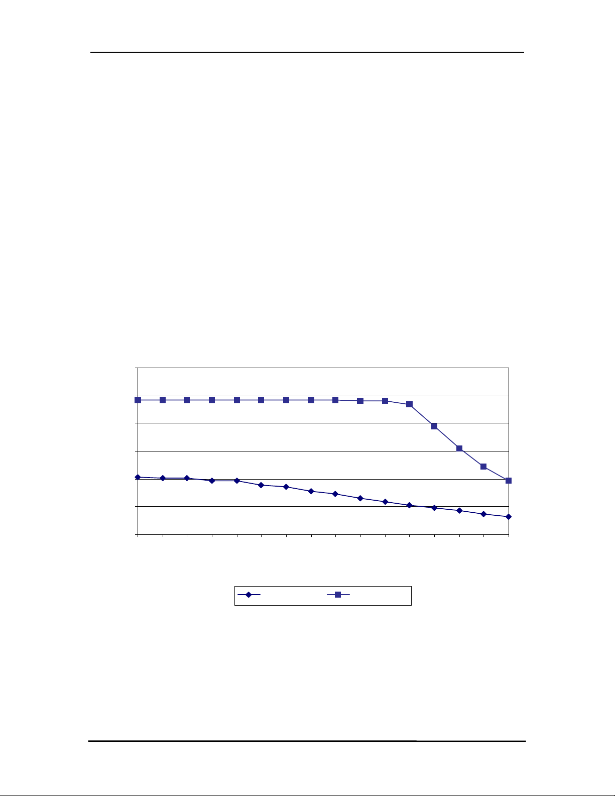
3.2.1
3.2.1 Received Signal Strength Indicator (RSSI)
3.2.13.2.1
The Received Signal Strength Indicator is used by the Host to determine the instantaneous signal
strength at the receiver. The Host must calibrate RSSI without a signal being presented to the receiver.
RSSI is invalid when a transceiver is transmitting. Calibration is accomplished by following the steps
listed below to find a minimum and maximum voltage value.
Figure 1 shows approximate RSSI performance. There are two versions of receivers used by the
AC5124. As of January of 2003 forward, only the New Revision receiver will be shipped. The RSSI pin
of the old revision requires the Host to provide a 27kΩ pull-down to ground. No pull-down should be
used with the new revision.
Received Signal Strength Indicator (RSSI)
Received Signal Strength Indicator (RSSI)Received Signal Strength Indicator (RSSI)
1) Power up only one transceiver in the coverage area.
2) Measure the RSSI signal to obtain the minimum value with no other signal present.
3) Power up a transceiver that is the opposite type of the one measured in Step 2 (i.e. if the
transceiver was a Client, power up a Server, otherwise power up a Client). Make sure the
two transceivers are in close proximity and measure RSSI to obtain a maximum value at
full signal strength.
Figure
Figure 1111 - RSSI Voltage vs. Received Signal Strength
Figure Figure
- RSSI Voltage vs. Received Signal Strength
- RSSI Voltage vs. Received Signal Strength - RSSI Voltage vs. Received Signal Strength
6
5
4
3
Voltage (V)
2
1
0
-20
-25
-30
-35
-40
-45
-50
-55
-60
Input Power (dBm)
New Revision Old Revision
-65
-70
-75
-80
-85
-90
-95
11/24/03 14

AC5124-10 Specifications
AC5124-10 Specifications
AC5124-10 SpecificationsAC5124-10 Specifications
3.2.2
3.2.2 In Range (IN_RANGE)
3.2.23.2.2
The IN_RANGE pin will be driven logic low when a Client is in range of a Server on the same Channel
and System ID. If a Client cannot hear a Server for the amount of time that is programmed in the
Range Refresh EEPROM address 32h, the Client drives the IN_RANGE pin logic high and enters a
search mode looking for a Server. As soon as it detects a Server, the IN_RANGE pin will be driven
logic low.
3.2.3
3.2.3 Baud Rate Selector (BDSEL)
3.2.33.2.3
The Baud Rate Selector (BDSEL) pin provides the OEM a default method of communicating with a
transceiver in the event the EEPROM baud rate parameters become corrupted. If Pin 26 is logic high
or not connected, the baud rate will default to that specified in EEPROM. If Pin 26 is logic low at
RESET, the baud rate will default to 9600 baud.
3.2.4
3.2.4 Microprocessor Reset (µP_RESET)
3.2.43.2.4
Microprocessor Reset (µP_RESET) is achieved by holding Pin 38 at logic high for a minimum of 2ms.
If µP_RESET is performed after power has been applied to a transceiver and is stable, the reset time
will be significantly less. At all other times, Pin 38 should be logic low. If Pin 38 is not connected, the
microprocessor will hold Pin 38 logic low.
In Range (IN_RANGE)
In Range (IN_RANGE)In Range (IN_RANGE)
Baud Rate Selector (BDSEL)
Baud Rate Selector (BDSEL)Baud Rate Selector (BDSEL)
Microprocessor Reset (µP_RESET)
Microprocessor Reset (µP_RESET) Microprocessor Reset (µP_RESET)
3.2.5
3.2.5 EEPROM Write Enable (WR_ENA)
3.2.53.2.5
EEPROM Write Enable (WR_ENA) is enabled when Pin 37 is logic low. Pin 37 must be logic low to
write to the EEPROM. The OEM must ensure a transceiver is NOT write-enabled during initial power
up or during a hardware RESET. Failure to do so may result in corruption of important EEPROM data.
EEPROM Write Enable (WR_ENA)
EEPROM Write Enable (WR_ENA)EEPROM Write Enable (WR_ENA)
11/24/03 15

AC5124-10 Specifications
AC5124-10 Specifications
AC5124-10 SpecificationsAC5124-10 Specifications
LECTRICAL
3.3
3.3 EEEE
3.33.3
LECTRICAL
LECTRICAL LECTRICAL
Pin
Pin Type
Type Name
PinPin
TypeType
2 I PKTMODE 0.2Vcc + 0.9 Vcc + 0.5 -0.5 0.2Vcc - 0.1 V
16 I RXD 0.2Vcc + 0.9 Vcc + 0.5 -0.5 0.2Vcc - 0.1 V
17 I RI_IN 2 Vcc + 1 -0.5 0.8 V
22 I DCD_IN 2 Vcc + 1 -0.5 0.8 V
26 I BDSEL 0.2Vcc + 0.9 Vcc + 0.5 -0.5 0.2Vcc - 0.1 V
27 I RTS 0.2Vcc + 0.9 Vcc + 0.5 -0.5 0.2Vcc - 0.1 V
34 I DTR 2 Vcc + 1 -0.5 0.8 V
37 I WR_ENA 0.7Vcc Vcc + 1 -0.3 0.5 V
38 I
PECIFICATIONS
PECIFICATIONS
SSSS
PECIFICATIONSPECIFICATIONS
Table
Table 2222 - DC Input Voltage Characteristics
Table Table
Name High Min.
NameName
µ
P_RESET 0.7Vcc Vcc + 0.5 -0.5 0.2Vcc - 0.1 V
Table
Table 3333 - DC Output Voltage Characteristics
Table Table
Pin
Pin Type
Type Name
PinPin
TypeType
11 O RSSI Analog Analog V
14 O TXD Vcc - 1.5 @ -60uA 0.45 @ 1.6mA V
15 O IN_RANGE 2.4 @ -4mA 0.45 @ 4mA V
19 O RI_OUT 2.4 @ -4mA 0.45 @ 4mA V
23 O CTS Vcc - 1.5 @ -60uA 0.45 @ 1.6mA V
32 O DSR 2.4 @ -4mA 0.45 @ 4mA V
36 O DCD_OUT 2.4 @ -4mA 0.45 @ 4mA V
- DC Input Voltage Characteristics
- DC Input Voltage Characteristics - DC Input Voltage Characteristics
High Min. High Max.
High Min.High Min.
- DC Output Voltage Characteristics
- DC Output Voltage Characteristics - DC Output Voltage Characteristics
Name High Min.
NameName
High Min. Low Max.
High Min.High Min.
High Max. Low Min.
High Max.High Max.
Low Min. Low Max.
Low Min.Low Min.
Low Max. Unit
Low Max.Low Max.
Low Max. Unit
Low Max.Low Max.
Unit
UnitUnit
Unit
UnitUnit
11/24/03 16

AC5124-10 Specifications
AC5124-10 Specifications
AC5124-10 SpecificationsAC5124-10 Specifications
4.
4. Serial Interface Modes
Serial Interface Modes
4.4.
Serial Interface ModesSerial Interface Modes
The AC5124 provides four Serial Interface Modes for interfacing to the Host, each having protocol
parameters that can be programmed for maximum system optimization. Serial Interface Modes 01, 02,
and 04 are referred to as Transparent Modes, indicating Host protocol is unnecessary for operation in
these modes – much like a serial cable. In addition, the transceiver-to-transceiver protocol for the
Transparent Modes is identical, allowing all three modes to coexist in the same network. Serial
Interface Mode 03, referred to as API Mode, is not interoperable with the Transparent Modes.
ERIAL
4.1
4.1 SSSS
4.14.1
Transparent Mode 01 is the most popular interface mode because it can be used for many serial cable
replacement applications that meet any or all of the following conditions:
ERIAL
ERIAL ERIAL
1) The Host always sends data packets that are the same size, allowing a transceiver to
2) The Host sends variable-sized data packets, all of which are equal to or smaller than the
NTERFACE
NTERFACE
IIII
NTERFACE NTERFACE
take advantage of the fixed packet length option.
Fixed Packet Length. A transceiver will wait until the Interface Timeout expires or until the
Fixed Packet Length size is reached. Therefore, if multiple packets and/or portions of
packets are sent before the Interface Timeout expires, the receiving transceiver Host
must be able to process the multiple packets and/or portions of packets.
MMMM
ODE
ODE
ODE ODE
RANSPARENT
01 – T
01 – T
01 – T01 – T
RANSPARENT
RANSPARENTRANSPARENT
IXED
, F
, F
, F, F
IXED
IXED IXED
ACKET
ACKET
PPPP
ACKET ACKET
ENGTH
ENGTH
LLLL
ENGTHENGTH
WITH
WITH
,
,
WITH WITH
, ,
IMEOUT
IMEOUT
TTTT
IMEOUTIMEOUT
Packets will be transmitted over the RF interface when one of the following conditions occurs:
1) The number of data bytes received over the serial interface is equal to the Fixed Packet
Length specified by the OEM at EEPROM addresses 43h and 44h (43h is the MSB). The
maximum packet size is 07FFh or 2KB.
2) A byte gap larger than the Interface Timeout specified by the OEM at EEPROM address
4Dh occurs. This can be set to 00h, 40h, 80h, or C0h designating 4ms, 40ms, 300ms,
and 2.6s timeouts, respectively.
Any packets larger than the Fixed Packet Length will be parsed and sent consecutively by a
transceiver. For example, if the Fixed Packet Length is 128 bytes and the Host sends 150 bytes,
a transceiver will send 128 bytes and then 22 bytes after the timeout expires, consecutively.
ERIAL
4.2
4.2 SSSS
4.24.2
Transparent Mode 02 is useful for applications where a particular character (such as a carriage return –
0Dh) is used to signify the end of each packet. The End Character is specified by the OEM at
EEPROM address 3Eh and can be set from 00h to FFh. Packets will be transmitted over the RF
interface when the OEM-defined End Character is received by a transceiver. The maximum packet
size is 07FFh or 2KB, including the End Character. Note that the End Character will be transmitted to
the Host.
ERIAL
ERIAL ERIAL
NTERFACE
NTERFACE
IIII
NTERFACE NTERFACE
MMMM
ODE
ODE
ODE ODE
02 – T
02 – T
02 – T02 – T
RANSPARENT
RANSPARENT
RANSPARENTRANSPARENT
, E
, E
, E, E
ND
ND
ND ND
HARACTER
HARACTER
CCCC
HARACTERHARACTER
11/24/03 17

AC5124-10 Specifications
AC5124-10 Specifications
AC5124-10 SpecificationsAC5124-10 Specifications
ERIAL
4.3
4.3 SSSS
4.34.3
API Mode is the most complex and detailed mode, where most of the control is given to the Host. This
mode may seem extensive at first glance; however, it follows a specific pattern of commands and
responses similar to an Ethernet protocol. The commands are grouped into two categories, System
Commands and Transceiver Commands. See Section 5, API Command Set
commands and definitions.
4.4
4.4 SSSS
4.44.4
In Transparent Mode 04, packets will be transmitted over the RF interface when the number of data
bytes received over the serial interface is equal to the Fixed Packet Length specified by the OEM at
EEPROM addresses 43h and 44h (43h is the MSB). The maximum packet size is 07FFh or 2KB. This
mode of operation is recommended for applications that meet any of the following conditions:
ERIAL
ERIAL ERIAL
ERIAL
ERIAL
ERIAL ERIAL
1) The Host always sends data packets that are the same size.
2) The Host sends variable-sized data packets, all of which are equal to or smaller than the
NTERFACE
NTERFACE
IIII
NTERFACE NTERFACE
NTERFACE
NTERFACE
IIII
NTERFACE NTERFACE
Fixed Packet Length. A transceiver will wait indefinitely until the Fixed Packet Length size
is reached. Therefore, multiple packets and/or portions of packets will be sent,
depending on the timing and size of the packets. As a result, the receiving transceiver
Host must be able to process the multiple packets and/or portions of packets.
MMMM
MMMM
ODE
ODE
ODE ODE
ODE
ODE
ODE ODE
03 – API
03 – API
03 – API03 – API
RANSPARENT
04 – T
04 – T
04 – T04 – T
RANSPARENT
RANSPARENTRANSPARENT
Section 5, API Command Set for the full list of
Section 5, API Command SetSection 5, API Command Set
IXED
, F
, F
, F, F
IXED
IXED IXED
ACKET
ACKET
PPPP
ACKET ACKET
ENGTH
ENGTH
LLLL
ENGTHENGTH
, N
, N
, N, N
O
O
O O
TTTT
IMEOUT
IMEOUT
IMEOUTIMEOUT
ERIAL
4.5
4.5 SSSS
4.54.5
The serial interface buffer provides 8 KBytes of memory segmented into four dynamic regions. In API
Mode, only one region is utilized. In all Transparent Modes, a buffer region is used each time a packet
release condition is met. As an example, in Transparent Mode 02, if 500 Bytes are transmitted,
including the specified End Character, 500 Bytes will be stored in the first region and the remaining 7.5
KBytes will be dynamically allocated for the next three packets. It is strongly recommended that CTS
or upper layer protocol with acknowledgements be used by the OEM when operating in any of the
Transparent Modes to prevent lost data. Otherwise, if all four buffers are filled and the Host continues to
send data over the serial interface, the data will be discarded by the transceiver. This condition can be
eliminated by using CTS.
4.6
4.6 AAAA
4.64.6
The AC5124 supports both Addressed and Broadcast Modes of communication in all Serial Interface
Modes. As necessary, refer to Section 5, API Command Set
6, Configuring the AC5124
6, Configuring the AC5124 for EEPROM address definitions.
6, Configuring the AC51246, Configuring the AC5124
ERIAL
ERIAL ERIAL
DDRESSED
DDRESSED
DDRESSED DDRESSED
NTERFACE
NTERFACE
IIII
NTERFACE NTERFACE
& B
& B
& B& B
UFFER
UFFER
BBBB
UFFERUFFER
ROADCAST
ROADCAST
ROADCAST ROADCAST
Section 5, API Command Set for API command definitions and Section
Section 5, API Command SetSection 5, API Command Set
OMMUNICATION
OMMUNICATION
CCCC
OMMUNICATIONOMMUNICATION
Section
SectionSection
11/24/03 18
 Loading...