

AeroComm 504830225 User Manual

19516 Amaranth Drive
Germantown, MD 20874
Phone 301-540-0700
Fax 301-540-5743
PROGRAMMABLE BI-DIRECTIONAL
BOOSTER AMPLIFIER
PBBA
OPERATION
INSTRUCTION MANUAL
MODEL 50289-RBA-800MHz
ALL INFORMATION CONTAINED IN THIS DOCUM ENT IS PROPRIETARY TO AEROCOMM,
AND SHALL NOT BE RELEASED, DISCLOSED OR DUPLICATED FOR ANY PURPOSE
OTHER THAN EVALUATION, INSPECTION, OR MAINTENANCE OF EQUIPMENT
DELINEATED HEREIN.
AEROCOMM IS NOT RESPONSIBLE FOR ANY EQUIPMENT REPAIRED OR ALTERED BY
PERSONS NOT AUTHORIZED BY AEROCOMM, OR NOT IN ACCORDANCE WITH
INSTRUCTIONS FURNISHED BY AEROCOMM . AEROCOMM IS NOT RESPONSIBLE FOR
EQUIPMENT RENDERED DEFECT IVE AS A RESULT OF MISUSE, IMPROPER R EPAIR, OR
ABNORMAL CONDITIONS OF OPERATION, NOR DOES AEROCOMM ASSUME ANY
LIABILITY FOR ANY CONSEQUENTIAL DAMAGE CAUSED BY SUCH EQUIPMENT.
SERVICE CONTRACTS OR CUSTOMER ASSISTANCE AGREEMENTS ARE AVAILABLE
FOR AEROCOMM PRODUCTS THAT REQUIRE MAINTENANCE AND/OR REPAIR.
AEROCOMM ALSO HAS AVAILABLE SERVICE AND CONSULTATION CONTRACTS FOR
ENTIRE SYSTEMS CONFIGURATIONS.
PROGRAMMABLE BI-DIRECTIONAL BOOSTER AMPLIFIER
PBBA
MODEL 50289-RBA-800MHz
P/N 50483-02-25
ACI-OIM-0001 RELEASED ER # AC—00 10 9/16 /99 2

TABLE OF CONTENTS
I. INTRODUCTION.................................................................................................................................4
PURPOSE OF MANUAL: .........................................................................................................................4
GENERAL SYSTEM OVERVIEW:..........................................................................................................5
PROGRAMMABLE BI-DIRECTIONAL BOOSTER AMPLIFIER OVERVIEW:..................................6
II. SPECIFICATIONS...............................................................................................................................8
GENERAL SPECIFICATIONS:................................................................................................................8
PROGRAMMABLE BI-DIRECTIONAL BOOSTER AMPLIFIER..........................................................8
SUB-ASSEMBLY SPECIFICATIONS: ....................................................................................................9
ATTENUATOR AMP MODULE #1 & #2...............................................................................................9
ATTENUATOR AMP MODULE #3........................................................................................................9
MMIC #1............................................................................................................................................... 10
MMIC #2............................................................................................................................................... 10
III. INSTALLATION............................................................................................................................ 11
IV. EQUIPMENT INITIALIZATION............................................................................................... 12
V. MAINTENANCE SCHEDULE........................................................................................................13
VI. THEORY OF OPERATION.........................................................................................................14
VII. TROUBLESHOOTING................................................................................................................15
III. SCHEMATICS................................................................................................................................ 16
ASSEMBLY DRAWINGS, PARTS LISTS..............................................................................................16
PROGRAMMABLE BI-DIRECTIONAL BOOSTER AMP...................................................................17
ATTENUATOR/AMPLIFIER MODULE #1 & #2..................................................................................18
ATTENUATOR/AMPLIFIER MODULE #3...........................................................................................19
MMIC AMPLIFIER #1............................................................................................................................20
MMIC AMPLIFIER #2............................................................................................................................21
RBA BPF MODULE................................................................................................................................22
IX. PERTINENT DOCUMENTATION.............................................................................................23
X. RECOMMENDED SPARES............................................................................................................24
ACI-OIM-0001 RELEASED ER # AC—00 10 9/16 /99 3

I. INTRODUCTION
PURPOSE OF MANUAL:
The purpose of this manual is to outline the installation, describe the operation,
and assist in the maintenance and trouble-shooting of the Programmable Bi-directional
Booster Amplifier (PBBA), Model 50289-RBA-800MHz.
MANUAL OUTLINE:
Section II: Section II covers the general specifications of the PBBA. This
section outlines the general, mechanical and electrical specifications including the
module specifications (sub-assemblies).
Section III: Section III covers the instructions for installing the PBBA.
Section IV: Section IV covers equipment initialization.
Section V: Section V is the recommended schedule of periodic maintenance
of the PBBA.
Section VI: Section VI covers the general “Theory of Operation” of the logic
and RF modules of a PBBA. This section is designed to aid in the understanding of the
PBBA.
Section VII: Section VII consists of diagrams, tables and procedures to assist
in the troubleshooting of a PBBA. This section is designed to guide a technician in
locating system fault(s) to the module. Included in t he section is a list of recommended
test equipment.
Section VIII: Section VIII consists of the schematics, assembly drawings, and
parts lists of the PBBA and its sub assemblies.
Section IX: Section IX consists of pertinent documents and supplemental
equipment manuals.
Section X: Section X lists the recommended spares for the PBBA.
ACI-OIM-0001 RELEASED ER # AC—00 10 9/16 /99 4

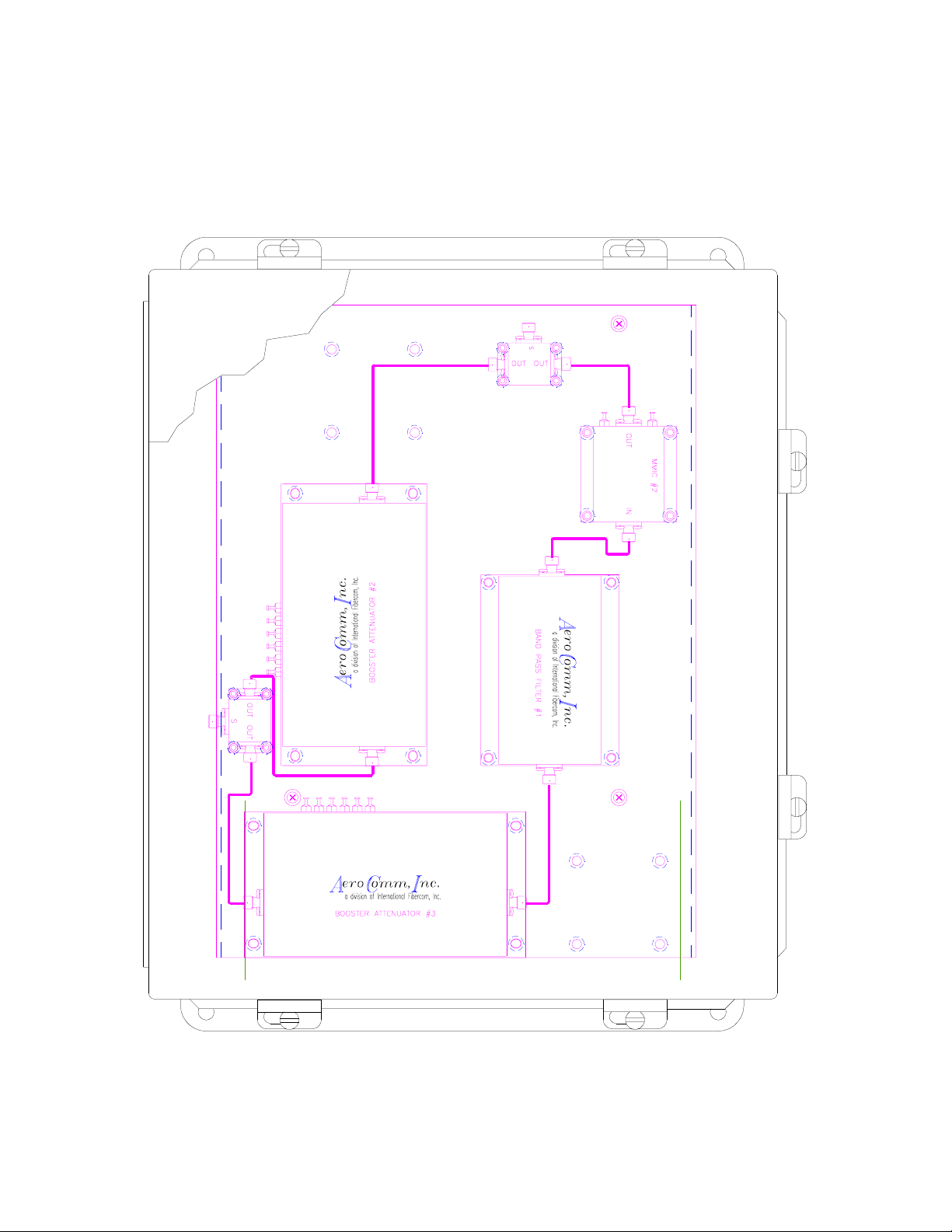
GENERAL SYSTEM OVERVIEW:
(refer to drawing 50483-01-19)
In an off-the-air to radiating cable system, signals received from the air are
rebroadcast onto the cable. Signals received on the cable are rebroadcast over the air,
e.g., talk-i n , talk-out.
In general, the forward channel, talk-out signals are generated f rom lower power
sources, e.g., handheld transceivers.
In an off-the-air to radiating cable multiple Channel Booster application, the
PBBA is utilized to enhance the performance of the talk-out in long cable systems.
ACI-OIM-0001 RELEASED ER # AC—00 10 9/16 /99 5

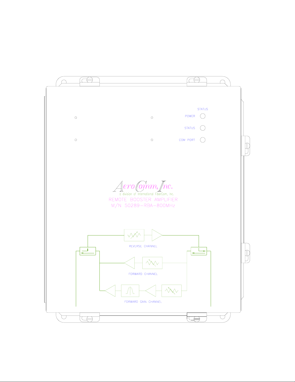
PROGRAMMABLE BI-DIRECTIONAL BOOSTER AMPLIFIER OVERVIEW:
(refer to figure 1)
The Programmable Bi-directional Booster Amplifier (PBBA) is a softwaredriven user-configurable unit for use in a multi-carrier low signal-level
environment. It is capable of eight (8) carriers and a composite power of –
20dBm.
The forward channel covers 100 to 2000MHz and within this band a
bandpass filter defined window called the In-Band has a user settable gain. The
factory default setting is 20dB. The Out-of-Band gain is also user settable and
the factory default setting is 0dB. The reverse channel covers 100 to 2000MHz
and has a user settable gain (see specifications for min/max gain/loss setting for
the forward and reverse channels.) Each channel uses a broadband
attenuator/amplifier module in which the attenuation is digitally set via computer
interface.
There are two (2) parallel amplifiers in the forward channel. One of the
forward channels called In-Band has a high gain amplifier chain and a band pass
filter to boost a specific window of frequencies within the 100 to 2000MHz
frequency of operation.
Its small package and light weight allows the user to conveniently install
the unit. Indicator lights allow the user to determine the status of the unit from a
distance. User-friendly software enhances the unit’s performance and user
interface.
ACI-OIM-0001 RELEASED ER # AC—00 10 9/16 /99 6
PROGRAMMABLE BI-DIRECTIONAL BOOSTER AMPLIFIER
PBBA
MODEL 50289-RBA-800MHz
P/N 50483-02-25
FIGURE 1
ACI-OIM-0001 RELEASED ER # AC—00 10 9/16 /99 7

II. SPECIFICATIONS
GENERAL SPECIFICATIONS:
PROGRAMMABLE BI-DIRECTIONAL BOOSTER AMPLIFIER
P/N 50483-02-25
MODEL # 50289-RBA-800 MHz
SPECIFICATIONS DEFAULT NOMINAL
Forward Channel: Talk-Out (Outbound)
Reverse Channel: Talk-In (Inbound)
Forward Freq. Range (Out-of-Band): 100 to 819/826 to 2000 MHz
Forward Freq. Range (In-Band): 821 to 824 MHz
Forward GAIN Range (Out-of-Band):
Forward GAIN Range (In-Band):
Reverse gain 100 to 2000 MHz:
RF Power out, 1 carrier, 1 dB
compression:
Max Power input 8 tone no damage: -12dBm/carrier
Max Power input: -20dBm
Amp Flatness: +0, -2dB
Intermodulation Distortion: -50dBc
Second Harmonic Output: -40dBc
Spurious Outputs: -80dBc
Noise Figures: <20dB
Input/Output VSWR: 1.3:1
Power Requirement: 120VAC
Input/Output Connector: Type N
AC Power Input: ¾” Conduit
Comm. Port: DB9F
Housing (Enclosure) Type: NEMA 4x
Enclosure Size: 14”x12”x6” (LxWxD)
Operation Temp.: -30 to +60ºC
20 ± 2dB
0 ± 2dB
-1dB ± 1dB
+17dBm
ADJUSTMENT
RANGE
11 to 26
FCC type acceptance
ACI-OIM-0001 RELEASED ER # AC—00 10 9/16 /99 8
 Loading...