

AeroComm 504830225 new Manual

1
PROGRAMMABLE BI -DIRECTIONAL
BOOSTER AMPLIFIER
PBBA
OPERATION
INSTRUCTION MANUAL
MODEL 50289-RBA-800MHz
MD Office:
19516 Amaranth Drive
Germantown, MD 20874
Phone 301-540-0700
Fax 301-540-5743
NJ Office:
560 Sylvan Avenue, 3rd Floor
Englewood Cliffs, NJ 07632
Phone 201-227-0066
Fax 201-227-0067
Email mail@aerocomm.cc
http://www.aerocomm.cc
ALL INFORMATION CONTAINED IN THIS DOCUMENT IS PROPRIETARY TO AEROCOMM,
AND SHALL NOT BE RELEASED, DISCLOSED OR DUPLICATED FOR ANY PURPOSE
OTHER THAN EVALUATION, INSPECTION, OR MAINTENANCE OF EQUIPMENT
DELINEATED HEREIN.
AEROCOMM IS NOT RESPONSIBLE FOR ANY EQUIPMENT REPAIRED OR ALTERED BY
PERSONS NOT AUTHORIZED BY AEROCOMM, OR NOT IN ACCORDANCE WITH
INSTRUCTIONS FURNISHED BY AEROCOMM. AEROCOMM IS NOT RESPONSIBLE FOR
EQUIPMENT RENDERED DEFECTIVE AS A RESULT OF MISUSE, IMPROPER REPAIR, OR
ABNORMAL CONDITIONS OF OPERATION, NOR DOES AEROCOMM ASSUME ANY
LIABILITY FOR ANY CONSEQUENTIAL DAMAGE CAUSED BY SUCH EQUIPMENT.
SERVICE CONTRACTS OR CUSTOMER ASSISTANCE AGREEMENTS ARE AVAILABLE
FOR AEROCOMM PRODUCTS THAT REQUIRE MAINTENANCE AND/OR REPAIR.
AEROCOMM ALSO HAS AVAILABLE SERVICE AND CONSULTATION CONTRACTS FOR
ENTIRE SYSTEMS CONFIGURATIONS.
2
PROGRAMMABLE BI-DIRECTIONAL BOOSTER AMPLIFIER
PBBA
MODEL 50289-RBA-800MHz
P/N 50483-02-25

3
TABLE OF CONTENTS
I. INTRODUCTION ................................................................................................................................................4
PURPOSE OF MANUAL: ........................................................................................................................................ 4
GENERAL SYSTEM OVERVIEW:.......................................................................................................................5
PROGRAMMABLE BI -DIRECTIONAL BOOSTER AMPLIFIER OVERVIEW:......................................6
II. SPECIFICATIONS..............................................................................................................................................8
GENERAL SPECIFICATIONS:..............................................................................................................................8
SUB-ASSEMBLY SPECIFICATIONS:................................................................................................................. 9
ATTENUATOR AMP MODULE..........................................................................................................................9
MMIC #1..................................................................................................................................................................9
MMIC #2..................................................................................................................................................................9
III. INSTALLATION ...........................................................................................................................................10
IV. OPERATION OF EQUIPMENT.............................................................................................................11
V. MAINTENANCE SCHEDULE.....................................................................................................................12
VI. THEORY OF OPERATION......................................................................................................................13
VII. TROUBLESHOOTING..............................................................................................................................14
III. SCHEMATICS,..............................................................................................................................................15
ASSEMBLY DRAWINGS, PARTS LISTS..........................................................................................................15
PROGRAMMABLE BI -DIRECTIONAL BOOSTER AMP............................................................................16
ATTENUATOR/AMPLIFIER MODULE #1......................................................................................................17
MMIC AMPLIFIER #1............................................................................................................................................18
MMIC AMPLIFIER #2............................................................................................................................................19
IX. PERTINENT DOCUMENTATION ........................................................................................................20
X. RECOMMENDED SPARES ..........................................................................................................................21

4
I. INTRODUCTION
PURPOSE OF MANUAL:
The purpose of this manual is to outline the installation, describe the operation,
and assist in the maintenance and trouble-shooting for the Programmable Bi-directional
Booster Amplifier (PBBA), Model 50289-RBA-800MHz.
MANUAL OUTLINE:
Section II: Section II covers the general specifications of the PBBA. This
section outlines the general, mechanical and electrical specifications including the
module specifications (sub-assemblies).
Section III: Section III covers the instructions for installing the PBBA, site
requirements, and equipment initialization.
Section IV: Section IV cover operating procedures.
Section V: Section V is the recommended schedule of periodic maintenance
of the PBBA.
Section VI: Section VI covers the general “Theory of Operations” of the logic
and modules of a PBBA. This section is designed to aid in the understating of the
PBBA.
Section VII: Section VIII consists of diagrams, tables and procedures to assist
in the troubleshooting of an PBBA. This section is designed to guide a technician in
locating system fault(s) to the module. Included in the section is a lis t of recommended
test equipment.
Section VIII: Section IX consists of the schematic, assembly drawings, and
parts list of the PBBA and it’s sub assemblies/
Section IX: Section X consists of pertinent documents and equipment
manuals to supplement sections III, VI, VIII and IX.
Section X: Section XI lists the recommend spares for the PBBA.

5
GENERAL SYSTEM OVERVIEW:
(refer to drawing 50483-01-19)
In an off-the-air to radiating cable system, signals received from the air are
rebroadcast onto the cable. Signals received on the cable are rebroadcast over the air,
e.g., talk-in, talk-out.
In an off-the-air to radiating cable multiple Channel Booster application, the
PBBA is utilized to enhance the performance of the talk-out in long cable systems.
In general, the forward channel, talk-out signals are generated from lower power
sources, e.g., handheld transceivers.

6
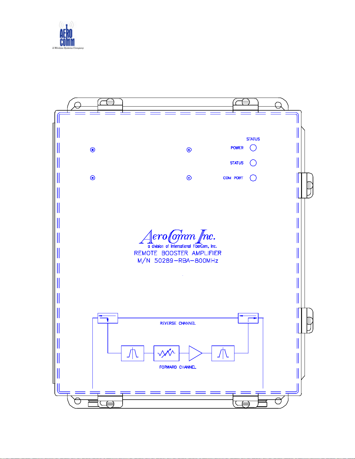
PROGRAMMABLE BI -DIRECTIONAL BOOSTER AMPLIFIER OVERVIEW:
(refer to figure 1)
The Programmable Bi-directional Booster Amplifier (PBBA) is a software-driven
user-configurable unit for use in a multi-carrier low signal-level environment. It is
capable of eight (8) carriers and a composite power of –20dBm.
The forward channel covers 100 to 2000MHz and within this band a bandpass
filter defined window called the In-Band has a user settable gain. The factory
default setting is 20dB. The Out-of-Band gain 0dB. The reverse channel covers
100 to 2000MHz and utilizes passive components/elements to pass these
frequencies. This channel has fixed insertion loss due to the passive
components/elements.
The forward In-Band channel uses a broadband attenuator/amplifier module in
which the attenuation is digitally set via computer interface.
The forward In-Band channel has a high gain amplifier chain and a band pass
filter to boost a specific window of frequencies within the 100 to 2000MHz
frequency of operation.
Its small package and light-weight allows the user to conveniently install the unit.
Indicator lights allow the user to determine the status of the unit from a distance.
A user-friendly software enhances the unit’s performance and user interface.
7
PROGRAMMABLE BI-DIRECTIONAL BOOSTER AMPLIFIER
PBBA
MODEL 50289-RBA-800MHz
P/N 50483-02-25
FIGURE 1
 Loading...