

Page 1

8 Channel Bi-Directional
Booster Amplifier
50289-BDA
Operations, Installation and Maintenance
Instruction Manual
Model 50289-BDA
ALL INFORMATION CONTAINED IN THIS DOCUMENT IS PROPRIETARY TO AeroComm, Inc.
AND SHALL NOT RELEASED, DISCLOSED, USED, OR DUPLICATED FOR ANY PURPOSE
OTHER THAN EVALUATION, INSPECTION, OR MAINTENANCE OF EQUIPMENT DELINEATED
HEREIN.
AEROCOMM UNCONDITIONALLY GUARANTEES THE MERCHANDISE PROVIDED AGAINST
DEFECTS OF ANY KIND INCLUDING, WITHOUT LIMITATION, DEFECTS IN OPERATION, DESIGN,
MATERIALS, AND WORKMANSHIP FOR TWO YEARS FROM THE DATE OF DELIVERY.
AEROCOMM IS NOT RESPONSIBLE FOR ANY EQUIPMENT REPAIRED OR ALTERED BY PERSONS
NOT AUTHORIZED BY AEROCOMM OR NOT IN ACCORDANCE WITH INSTRUCTIONS
FURNISHED BY AEROCOMM. AEROCOMM. IS NOT RESPONSIBLE FOR EQUIPMENT RENDERED
DEFECTIVE AS A RESULT OF MISUSE, IMPROPER REPAIR, OR ABNORMAL CONDITIONS OF
OPERATION, NOR DOES AEROCOMM ASSUME ANY LIABILITY FOR ANY CONSEQUENTIAL
DAMAGE CAUSED BY SUCH EQUIPMENT.
SERVICE CONTRACTS OR CUSTOMER ASSISTANCE AGREEMENTS ARE AVAILABLE FOR
AEROCOMM. PRODUCTS THAT REQUIRE MAINTENANCE AND/OR REPAIR. AEROCOMM ALSO
HAS SERVICE AND CONSULTATION CONTRACTS FOR ENTIRE SYSTEM CONFIGURATIONS.
Page 2
800MHz Bi-directional Booster Amplifier 50289-BDA
Page 3

800MHz BDA
Model 50289-BDA
Specifications
Frequency Range: 806-824MHz, 851-869MHz
Pre-selectors: 819-824MHz, 864-869MHz
Talk-Out, Outband: 821-823MHz
Talk-In, Inband: 866-869MHz
Channel Spacing: 25kHz
Channel Bandwidth: 15kHz
Phase Noise: 10kHz - - 90dBc/Hz
RF Frequency Accuracy: Signal exactly
Adjacent Channel Selectivity: 70dB @ +17.5kHz
RF Output Power (to cable): +31dBm per carrier
RF Output Power (to antenna): +25dBm per carrier
Variation of Output Power with Input Level: +0, -1dB
Max Passband Ripple (full band): 2dB
Max Passband Ripple (100Khz segment): 0.1dB
Amplifier Input Port Burnout
(no damage I/O segment):
Amplifier Output Damage (no damages): open/short
Reliability: 50K hours minimum
Intermodulation/Crossmodulation Distortion: -60dBc
Channel to Channel Isolation: -70dBc
-90dBm Input Output +31dBm (High Band)
Duty Cycle: Continuous
RF Spurious Output
(0.5-800MHz, 1-2.5GHz):
RF Spurious Output (800-1000MHz): -85dBc max
Operating Temperature Range:
System Noise Figure: <9dB
Input/Output Impedance: 50 ohms nominal
Input/Output VSWR: 1.5:1, worst case
Input/Output Connectors at top of cabinet: Type N Female
Input Power: 110vac
Passband Group Delay: 220 microseconds
Alternate Power Source, battery Backup: +12vdc @ 56 amps (High Band)
Operation Conditions: Unconditionally stable
Time-out timer 1 sec to 99 minutes and 59 seconds
Annunciating LEDs: Power
Enclosure: NEMA 12 72”Hx24”Wx24”D
Number of Enclosures: 2 (1 High Band/1 Low Band)
Weight: <650 lbs each
@-15dBm
Output +25dBm (Low Band)
-60dBc
-20°C to +60°C
+12vdc @ 38 amps (Low Band)
PLL Lock Detect
Status – Key On
Fault
50289-BDA
USE OR DISCLOSURE OF DATA CONTAINED ON THIS PAGE IS SUBJECT TO THE
RESTRICTION ON THE TITLE PAGE OF THIS MANUAL
3
Page 4

800MHz BDA
Model 50289-BDA
Specifications Continue:
DC Power Supply:
No. per enclosure: High Band: 3 (1 Dual Chassis/ 1 Single)
Low Band: 2 (1 Dual Chassis)
Input: 105-125 VAC, 50-400Hz, single phase
Output (each supply): 12 VDC+/- 0.5V @20 amps
Operating Temperature:
Battery Charger:
Type: Multi-Stage (Bulk/Absorption/Float)
DC Output: 13.8-14.8Vdc (depending on setting)
AC Input: 95-125 VAC
Charging Rate: Bulk Charge: 40 amps max.
Absorption: 5 amps max.
Float: 0.05 amps
Battery:
Specifications dependant on required UPS cycle
System Load: 95 amp/hr
Software:
Title: 800MHz-Linc (50486-09-01)
Version: 1.0
Operator, User Functions: Time-out Timer (set time interval)
Mode (Keyed or Continuous)
Technician Functions: Set Attenuation
Set Frequency
Set RSSI Attack
Peripheral Requirements:
Operating System (requirements): Window 95, Windows 98, or Windows NT 4.0
Computer or Laptop (requirements): 486DX66Mhz (minimum)
Communication, Serial Port (requirements): 4800 baud,
N8+1 (8 bits, no parity)
-20°C to +70°C
Optionally Provided or User Supplied
Optionally provided or User supplied:
(or higher)
50289-BDA
USE OR DISCLOSURE OF DATA CONTAINED ON THIS PAGE IS SUBJECT TO THE
RESTRICTION ON THE TITLE PAGE OF THIS MANUAL
4
Page 5

TABLE OF CONTENTS
SECTION I INSTALLATION............................................................................................................... 9
INTRODUCTION .............................................................................................................................. 9
DETAILED INSTALLATION INSTRUCTIONS ............................................................................... 9
MECHANICAL INSTALLATION OF THE CABINETS.................................................................... 9
AC POWER CONNECTION............................................................................................................ 10
SETTING THE THERMOSTATS .................................................................................................... 10
CONNECT EXTERNAL RF CABLING........................................................................................... 11
INSTALLING POWER SUPPLIES & BATTERY CHARGER ......................................................... 11
INSTALLING THE POWER AMPLIFIER....................................................................................... 15
INSTALLING THE IF CHANNEL MODULES................................................................................ 16
INTERNAL RF CABLE INSTALLATION....................................................................................... 18
IF MODULE CABLING ........................................................................................................................18
DUPLEXER CABLING.........................................................................................................................19
DUPLEXER CABLING (CONTINUED)................................................................................................22
POWER AMPLIFIER CABLING...........................................................................................................23
BATTERY CONNECTION.............................................................................................................. 24
POWER UP SEQUENCE................................................................................................................. 25
SECTION II OPERATION PROCEDURES...................................................................................... 27
USER’S SOFTWARE....................................................................................................................... 28
CHANGING THE TIME-OUT DURATION..................................................................................... 29
CHANGING THE MODE SETTING................................................................................................ 29
TECHNICIAN’S SOFTWARE......................................................................................................... 29
SETTING THE ATTACK TIME ...................................................................................................... 29
CHANGING THE INPUT ATTENUATION..................................................................................... 29
SETTING THE FREQUENCY ......................................................................................................... 30
CHANGING THE CHANNEL ID..................................................................................................... 30
CHANGING THE CHANNEL SERIAL NUMBER.......................................................................... 30
SECTION III MAINTENANCE.......................................................................................................... 31
BDA MAINTENANCE: ................................................................................................................... 31
AIR FILTRATION:................................................................................................................ 31
CABLE INSPECTION: .......................................................................................................... 31
ENCLOSURE INSPECTION:................................................................................................. 31
OPERATIONAL TESTS: ....................................................................................................... 31
BATTERY MAINTENANCE (BACKUP BATTERY):..................................................................... 31
ADDITIONAL INFORMATION...................................................................................................... 31
SECTION IV RECOMMENDED SPARES........................................................................................ 32
SECTION V THEORY OF OPERATION......................................................................................... 33
DUPLEXER: .................................................................................................................................... 36
TALK-IN BA: ........................................................................................................................ 36
TALK-OUT BA:..................................................................................................................... 36
LNA/8-WAY SPLITTER:....................................................................................................... 36
CHANNEL MODULE (IF MODULE):............................................................................................. 36
IF CHANNEL MODULE: ...................................................................................................... 37
MICRO CONTROLLER: ....................................................................................................... 37
THE MOTHERBOARD: ........................................................................................................ 37
RF POWER AMPLIFIER/8-WAY COMBINER:.............................................................................. 37
THE HIGH BAND BA: .................................................................................................................... 38
50289-BDA
USE OR DISCLOSURE OF DATA CONTAINED ON THIS PAGE IS SUBJECT TO THE
RESTRICTION ON THE TITLE PAGE OF THIS MANUAL
5
Page 6

THE LOW BAND BA: ..................................................................................................................... 38
SECTION VI USER’S GUIDE............................................................................................................ 43
OVERVIEW..................................................................................................................................... 43
PROGRAM INSTALLATION .......................................................................................................... 43
PROGRAM STARTUP .................................................................................................................... 43
MAIN SCREEN ............................................................................................................................... 44
COMMUNICATION CONNECTION .............................................................................................. 45
SETTING A TIME-OUT TIME ........................................................................................................ 46
CHANGING THE MODE ................................................................................................................ 47
EXITING THE SOFTWARE............................................................................................................ 47
ADDITIONAL INFORMATION...................................................................................................... 48
SECTION VII TECHNICIAN’S GUIDE............................................................................................ 49
ACTIVATING TECHNICIAN FUNCTIONS ................................................................................... 50
CLOSING THE TECHNICIAN FUNCTIONS.................................................................................. 50
SETTING RSSI ATTACK TIME...................................................................................................... 51
CHANGING THE CHANNEL ID..................................................................................................... 51
CHANGING THE CHANNEL SERIAL NUMBER.......................................................................... 52
SETTING ATTENUATION ............................................................................................................. 52
SETTING A FREQUENCY.............................................................................................................. 52
CLOSING THE TECHNICIAN FUNCTIONS.................................................................................. 54
SECTION VIII TUNE UP PROCEDURE........................................................................................... 55
SECTION IX FCC CERTIFICATION LABEL LOCATION............................................................ 56
50289-BDA
USE OR DISCLOSURE OF DATA CONTAINED ON THIS PAGE IS SUBJECT TO THE
RESTRICTION ON THE TITLE PAGE OF THIS MANUAL
6
Page 7

Table of Figures
Figure 1. Thermostat & Electrical Power InFigure 1. Thermostat & Electrical Power In
stallationstallation ......................................................1010
Figure 2. External RF Cabling InstallationFigure 2. External RF Cabling Installation
........................................................................ 1111
Figure 3. Equipment Cabinet Configuration Figure 3. Equipment Cabinet Configuration
as Shippedas Shipped ......................................................1212
Figure 4. Battery Charger ModuleFigure 4. Battery Charger Module ................1313
Figure 5. Power ConnectionsFigure 5. Power Connections on the Rear of on the Rear of
the Power Supply and Charger Module the Power Supply and Charger Module ( (
as viewed from the toas viewed from the top)p) .......................... 1515
Figure 6. Power & Signal Connections on thFigure 6. Power & Signal Connections on th
e Rear of the Power Amplifiere Rear of the Power Amplifier .............. 1616
Figure 7. IF Channel Module Jumper LocationFigure 7. IF Channel Module Jumper Location
........................................................................ 1717
Figure 8. Semi-Rigid Cables for ConnecFigure 8. Semi-Rigid Cables for Connectingting
IF Channel Modules & 8-Way Splitter IF Channel Modules & 8-Way Splitter .. 1919
Figure 9. Arrangement of Internal RF CabliFigure 9. Arrangement of Internal RF Cabli
ngng ...................................................................... 2020
Figure 10. Semi-Rigid Cables Connecting IF Figure 10. Semi-Rigid Cables Connecting IF
Channel Modules & Power AmplifierChannel Modules & Power Amplifier ........2121
Figure 11. Semi-Rigid Cable for ConnectingFigure 11. Semi-Rigid Cable for Connecting
the Duplexer to the 8-Way Splitter the Duplexer to the 8-Way Splitter .... 2222
Figure 12. Semi-Rigid Cable Connecting theFigure 12. Semi-Rigid Cable Connecting the
Power Amplifier to the Cabinet-Mounted Power Amplifier to the Cabinet-Mounted
Feed-Thru Connector Feed-Thru Connector .................................. 2323
FiguFigure 13. Battery Cabling Installationre 13. Battery Cabling Installation .. 2424
Figure 14. Main Power Switches for Power SFigure 14. Main Power Switches for Power S
upplies and Battery Status Panelupplies and Battery Status Panel ..........2626
Figure 15. Normal LED Illuminations after PFigure 15. Normal LED Illuminations after P
ower Up ower Up ..........................................................2626
Figure 16. Channel Module LED Indicator IllFigure 16. Channel Module LED Indicator Ill
umination Patternsumination Patterns ......................................2828
Figure 17. Normal Channel ID Numbering SchFigure 17. Normal Channel ID Numbering Sch
emeeme .................................................................... 3030
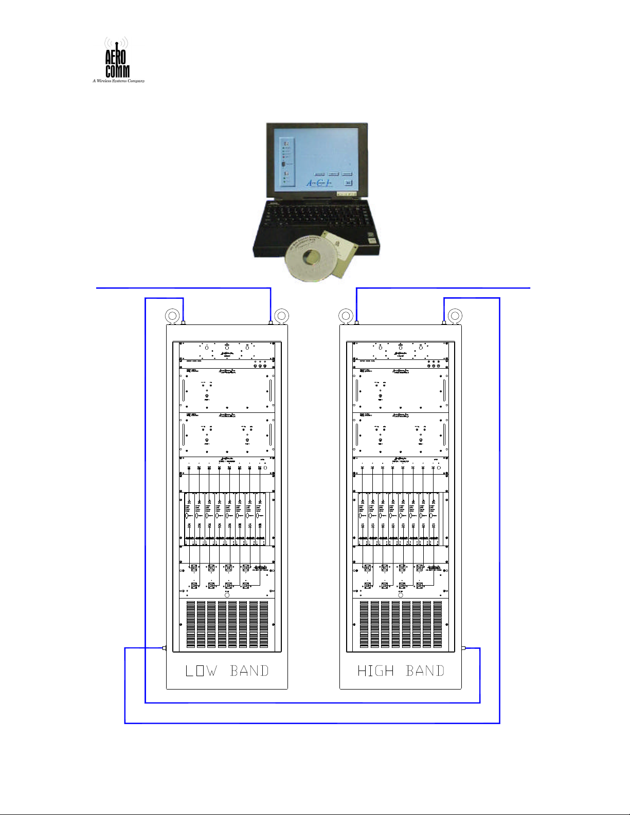
Figure 18. Overall System Figure 18. Overall System .......................... 3434
Figure 19. SysteFigure 19. System Outlinem Outline ............................ 3535
Figure 20. Power Distribution Unit OutlineFigure 20. Power Distribution Unit Outline
........................................................................ 4040
Figure 21. Power Distribution High BandFigure 21. Power Distribution High Band .. 4141
Figure 22. Power Distribution Low BandFigure 22. Power Distribution Low Band .... 4242
Figure 23. 800MHz-Linc Main screenFigure 23. 800MHz-Linc Main screen ................ 4444
Figure 24. 800 MHz-Linc Main Screen with ConFigure 24. 800 MHz-Linc Main Screen with Con
nection Error windownection Error window ................................ 4545
Figure 25. Set Time Out windowFigure 25. Set Time Out window.................... 4646
Figure 26. Set ModFigure 26. Set Mode windowe window............................ 4747
Figure 27. Exit confirmation windowFigure 27. Exit confirmation window .......... 4848
Figure 28. 800 MHz-Linc about windowFigure 28. 800 MHz-Linc about window .......... 4949
Figure 29. 800MHz-Linc Main ScreenFigure 29. 800MHz-Linc Main Screen .............. 5050
Figure Figure 30. Set RSSI Attack window30. Set RSSI Attack window .............. 5151
Figure 31. Set Attenuation windowFigure 31. Set Attenuation window.............. 5252
Figure 32. Set Frequency windowFigure 32. Set Frequency window .................. 5353
50289-BDA
USE OR DISCLOSURE OF DATA CONTAINED ON THIS PAGE IS SUBJECT TO THE
RESTRICTION ON THE TITLE PAGE OF THIS MANUAL
7
Page 8

Figure 33. 800 MHz-Linc screenFigure 33. 800 MHz-Linc screen ...................... 5454
50289-BDA
USE OR DISCLOSURE OF DATA CONTAINED ON THIS PAGE IS SUBJECT TO THE
RESTRICTION ON THE TITLE PAGE OF THIS MANUAL
8
Page 9

SECTION I INSTALLATION
INTRODUCTION
AeroComm strongly recommends that the user install the two rack enclosures for the
system by bolting them down onto level concrete flooring. The user must equip the
concrete floor with appropriate anchors and drill the floor of the cabinet to match.
AeroComm recommends stainless steel wedge anchors with a minimum diameter of 3/8”
and a thread length of 2 ¼”. The hole pattern in the concrete floor and in the floor of the
cabinet should be arranged such that the anchor studs are centered 2” from each wall of
the cabinet in each of the four corners.
WARNING
FAILURE TO SECURE THE CABINET AS RECOMMENDED MAY RESULT IN
CABINET TIP-OVER DURING INSTALLATION OF THE POWER SUPPLIES.
AeroComm recommends installing the two cabinets 3 feet apart. This separation distance
provides easy access to the sides and top of each cabinet; additionally, this separation
provides necessary RF isolation of the two units. Under no circumstances should the two
units be located more than 10 feet from one another; separation distances greater than 10
feet will increase path loss on the RF cables connecting the two units and result in nonoptimal operation.
DETAILED INSTALLATION INSTRUCTIONS
MECHANICAL INSTALLATION OF THE CABINETS
Determine the bolt pattern to be used for anchoring the two cabinets.
Install anchors in concrete floor & match drill cabinet floors.
Position cabinets over the floor anchors and fasten the cabinets to the floor.
WARNING
ENSURE AC POWER SERVICE LINES ARE NOT LIVE PRIOR TO
CONNECTING TO THE EQUIPMENT CABINETS.
50289-BDA
USE OR DISCLOSURE OF DATA CONTAINED ON THIS PAGE IS SUBJECT TO THE
RESTRICTION ON THE TITLE PAGE OF THIS MANUAL
9
Page 10
AC POWER CONNECTION
Install AC power conduit. Each cabinet is configured with clamping-ring hardware
suitable for attachment of ½” electrical conduit.
Each cabinet is fitted with an electrical junction box inside at the top rear of the cabinet.
Remove the cover plate and connect the AC source lines to the appropriate terminals in
the junction box. Refer to figure 1. Re-install the cover plate.
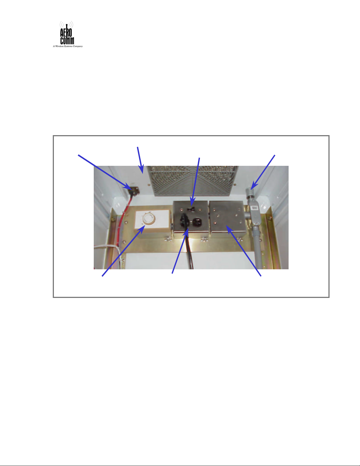
Figure 1. Thermostat & Electrical Power InFigure 1. Thermostat & Electrical Power In
stallationstallation
BATTERY
CABINET CEILING INCOMING
CONNECTION
THERMOSTAT MAIN AC POWER
OUTLETS FOR CABINET
COOLING FAN
POWER SWITCH
AC SERVICE CONDUIT
ELECTRICAL
JUNCTION BOX
SETTING THE THERMOSTATS
Set the thermostat inside each cabinet for 90-95ºF (32-35°C). This will keep the cabinet
at optimal operating temperatures. Refer again to Figure 1. The Thermostat is marked
with three dots between 80ºF and 130ºF(27-54°C). Turn the thermostat dial so the pointer
is just past the first dot above 80ºF (27°C).
NOTE
THE THERMOSTATS MAY BE ADJUSTED AFTER INSTALLATION BY
REMOVING THE GRILL AND FILTER ON THE TOP OF EACH CABINET. THE
USER CAN THEN REACH THROUGH THE ACCESS HOLE TO ADJUST THE
THERMOSTAT SETTINGS.
50289-BDA
USE OR DISCLOSURE OF DATA CONTAINED ON THIS PAGE IS SUBJECT TO THE
RESTRICTION ON THE TITLE PAGE OF THIS MANUAL
10
Page 11
TALK IN
HIGH BAND
TALK OUT
LOW BAND
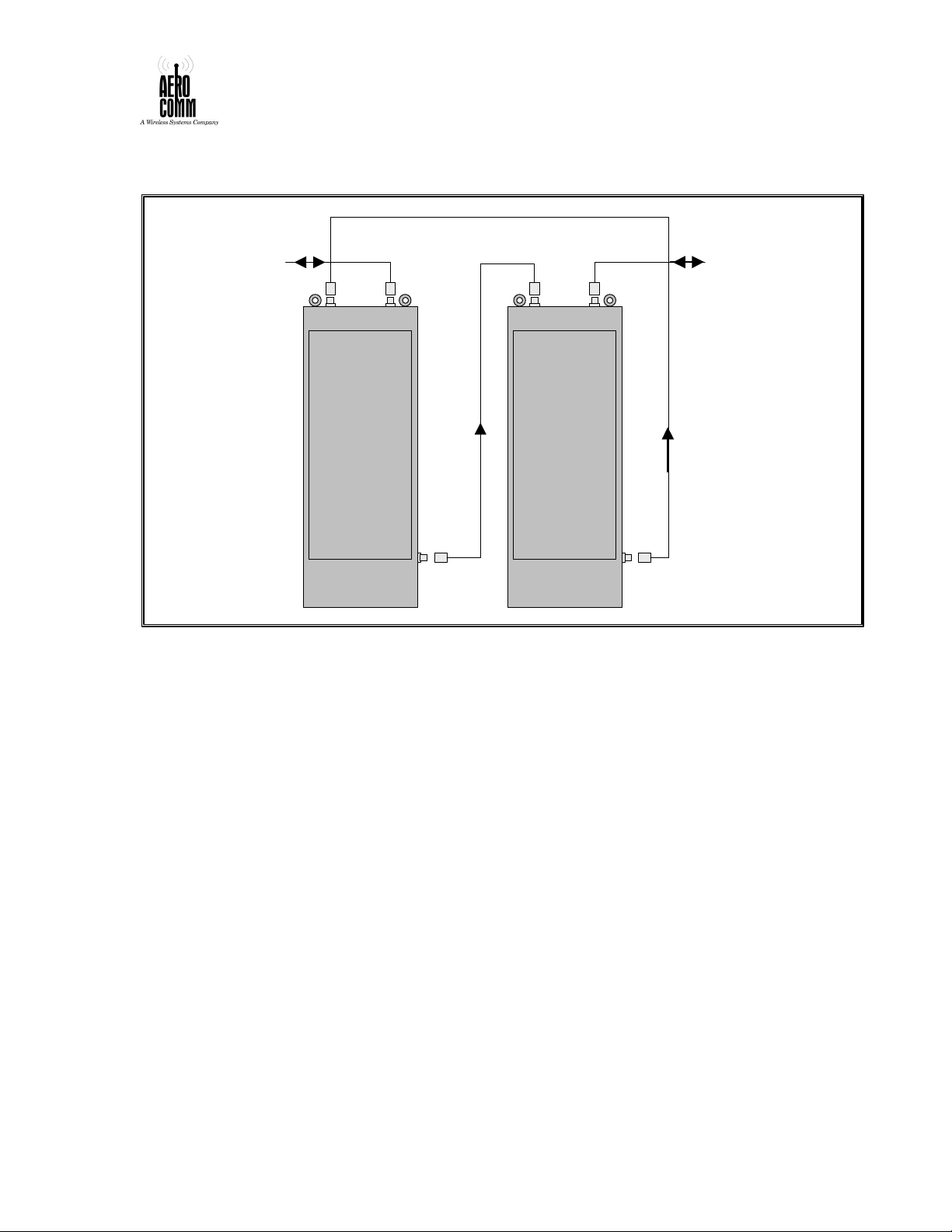
Figure 2. External RF Cabling InstallationFigure 2. External RF Cabling Installation
TO ROOF ANTENNA TO RADIATING CABLE
CONNECT EXTERNAL RF CABLING
Connect the two cabinets to one another using low-loss ½” heli-axial cable as shown in
the Figure 2 above.
Connect the cable leading to the roof antenna to the type N connector on the top right
(when viewed from the front) of the “Talk In” / High Band cabinet.
Connect the radiating cable to the type N connector on the top right (when viewed from
the front) of the “Talk Out” / Low Band cabinet.
INSTALLING POWER SUPPLIES & BATTERY CHARGER
The power supplies and battery charger are the first items to be loaded into the equipment
cabinets by the user. The following items were shipped in each cabinet (listed from top to
bottom of the cabinet):
I. Duplexer
II. Power Control Breaker Panel
III. LNA / 8-Way Splitter
IV. VME Chassis for Channel Cards
V. Blower
1. Verify equipment listed above is installed in each cabinet. Refer to Figure 3 below.
50289-BDA
USE OR DISCLOSURE OF DATA CONTAINED ON THIS PAGE IS SUBJECT TO THE
RESTRICTION ON THE TITLE PAGE OF THIS MANUAL
11
Page 12
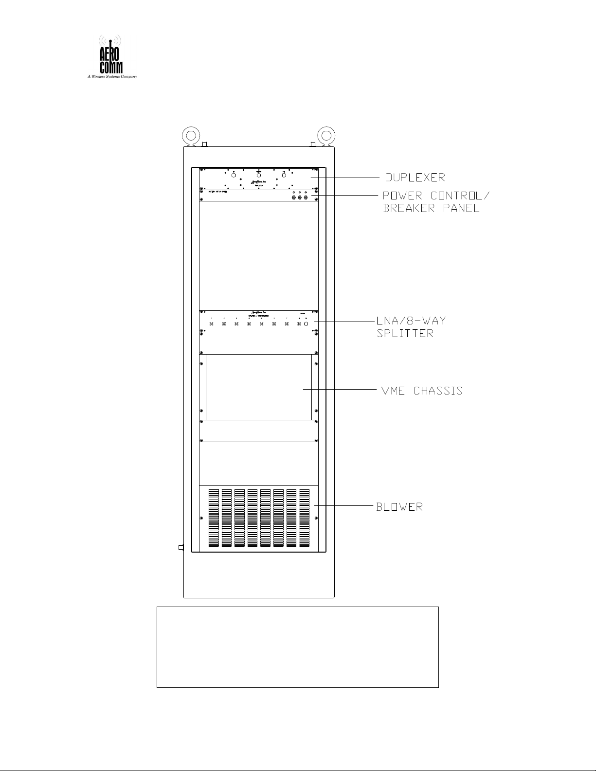
Figure 3. Equipment Cabinet Configuration Figure 3. Equipment Cabinet Configuration
as Shippedas Shipped
50289-BDA
WARNING
THE DUAL POWER SUPPLY MODULES WEIGH APPROXIMATELY 60
POUNDS.
THE SINGLE POWER SUPPLY MODULE WEIGHS ABOUT 40 POUNDS.
THE BATTERY CHARGER MODULE WEIGHS ABOUT 15 POUNDS.
TWO PEOPLE SHOULD LIFT THE MODULES TOGETHER TO
PREVENT INJURY DURING INSTALLATION INTO THE CABINETS.
USE OR DISCLOSURE OF DATA CONTAINED ON THIS PAGE IS SUBJECT TO THE
RESTRICTION ON THE TITLE PAGE OF THIS MANUAL
12
Page 13
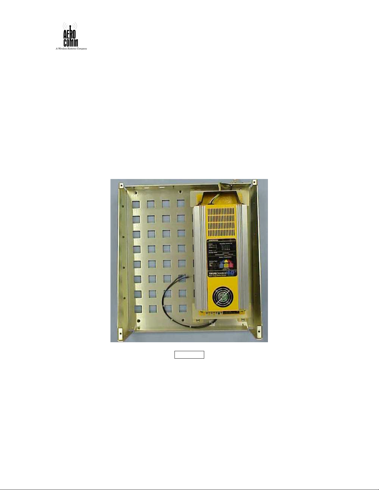
2. Locate the dual power supply modules (2 ea.), the single power supply module (1 ea.)
and the battery charger module (1 ea.).
The modules are distinguished by the following features:
• The dual power supply modules have two large gold power supplies (made by
Acopian) mounted side-by-side in the chassis.
• The single power supply module has a single gold Acopian power supply mounted on
the left side of the chassis (when viewed from the front).
• The battery charger module has a single yellow TrueCharge 40™ battery charger
(made by StatPower) mounted on the right side of the chassis (when viewed from the
front). The battery charger module is shown in Figure 4.
Figure 4. Battery Charger ModuleFigure 4. Battery Charger Module
CAUTION
MAKE SURE THE POWER SUPPLIES AND CHARGER ARE SWITCHED OFF
PRIOR TO INSTALLATION. THESE UNITS ARE OFF WHEN THE CIRCUIT
BREAKER PUSS-PULL SWITCHES ON THE FRONT PANEL ARE PULLED
OUT (THE WHITE BAND AROUND THE BODY OF THE SWITCH IS VISIBLE).
3. Load one dual power supply module into the High Band equipment cabinet. This
module goes directly above the LNA / 8-Way Splitter Module.
50289-BDA
USE OR DISCLOSURE OF DATA CONTAINED ON THIS PAGE IS SUBJECT TO THE
RESTRICTION ON THE TITLE PAGE OF THIS MANUAL
13
Page 14

4. Attach the power connections on the rear of the chassis. Refer to Figure 5 below.
Note that there are two connections that must be made on the left side of the module
(as viewed from the front). The longer harness lead in the cabinet should be attached
to the connector further in from the left edge of the cabinet.
5. Load the other dual power supply into the Low Band equipment cabinet, directly
above the LNA / 8-Way Splitter Module.
6. Attach the power connections on the rear of the chassis as in step 4.
7. Load the single power supply into the High Band equipment cabinet, directly above
the dual power supply module.
8. Attach the power connections on the rear of the chassis. Note that the single power
supply has only one connection that must be made on the left side of the module (as
viewed from the front).
9. Load the battery charger supply into the Low Band equipment cabinet, directly above
the dual power supply module.
10. Attach the AC power connection on the right rear of the chassis.
11. Connect unterminated AC power leads to the rear of the charger using the wire nuts
provided. Install the cover over the wire nut junctions per the manufacturer’s
instructions provided in the appendix.
50289-BDA
USE OR DISCLOSURE OF DATA CONTAINED ON THIS PAGE IS SUBJECT TO THE
RESTRICTION ON THE TITLE PAGE OF THIS MANUAL
14
Page 15
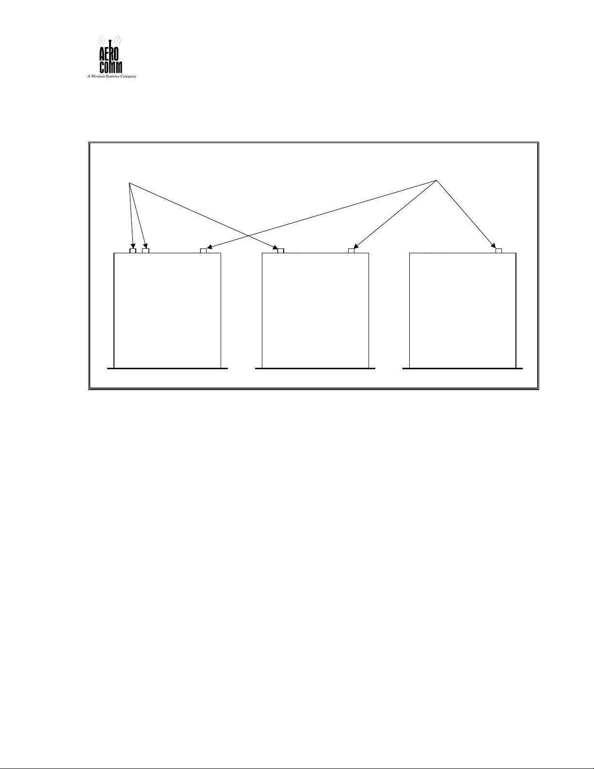
Figure 5. Power ConnectionsFigure 5. Power Connections on the Rear of on the Rear of
the Power Supply and Charger Module the Power Supply and Charger Module ( (
as viewed from the top)as viewed from the top)
3-PIN FEMALE CIRCULAR CONNECTORS
AMP206425-1
(DC POWER OUTPUT)
J1 J2 J3
DUAL
POWER SUPPLY
J1 J3
SINGLE
POWER SUPPLY
3-PIN MALE CIRCULAR CONNECTORS
AMP206036-1
(AC POWER INPUT)
J3
BATTERY
CHARGER
NOTE
ALL FREQUENCY DEPENDENT MODULES FOLLOW A FIXED SERIAL-
NUMBER CONVENTION. LOW-BAND MODULES ARE HAVE “1XX”
SERIAL NUMBERS AND HIGH-BAND MODULES ARE HAVE “2XX"
SERIAL NUMBERS.
INSTALLING THE POWER AMPLIFIER
Locate the two power amplifier modules.
Load the “2XX” power amplifier module into the High Band equipment cabinet, between
the IF Channel Module chassis and the blower assembly. Repeat this procedure for the
Low Band equipment cabinet using the “1XX” module.
Attach the power & signal cables in the cabinet to the mating connectors on the rear of
the Power Amplifier chassis as shown in Figure 6 on the next page.
50289-BDA
USE OR DISCLOSURE OF DATA CONTAINED ON THIS PAGE IS SUBJECT TO THE
RESTRICTION ON THE TITLE PAGE OF THIS MANUAL
15
Page 16
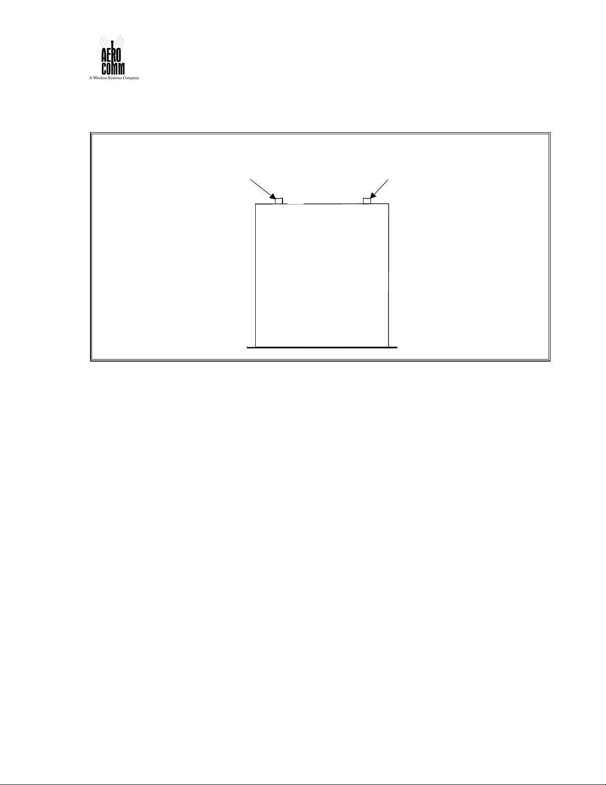
Figure 6. Power & Signal Connections on thFigure 6. Power & Signal Connections on th
CONNECTOR (DC POWER)
CONNECTOR (SIGNAL)
e Rear of the Power Amplifiere Rear of the Power Amplifier
(as viewed from the top)(as viewed from the top)
7-PIN MALE CIRCULAR
AMP 206137-1
POWER AMPLIFIER
9-PIN MALE CIRCULAR
AMP 206705-1
INSTALLING THE IF CHANNEL MODULES
The channel slots have been factory preset to be installed in order, from low to high
frequency, from left to right, in the VME-style IF Channel rack located in lower middle
of each cabinet.
Note that each IF channel module is labeled with the frequency to which it was factorytuned; the frequency is written on the “TESTED” sticker located on the top rear corner of
the RF enclosure in each module.
Also note the bank of jumpers at the rear of each IF channel module; the jumper position
determines the keying of the power amp directly below the IF channel rack and,
consequently, which slot each IF channel module should be placed in. The IF channel
module slots are ordered 1 through 8 from left to right.
The factory preset frequencies and jumper settings for the High- and Low-Band IF
Channel Modules are listed in Table 1. Jumper location is depicted in Figure 7
50289-BDA
USE OR DISCLOSURE OF DATA CONTAINED ON THIS PAGE IS SUBJECT TO THE
RESTRICTION ON THE TITLE PAGE OF THIS MANUAL
16
Page 17
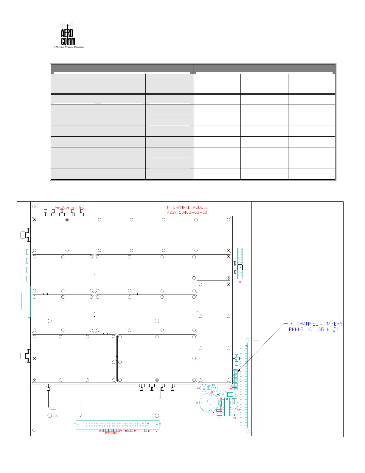
Table 1. Factory Preset IF Channel ModuTable 1. Factory Preset IF Channel Modu
LOW BAND / TALK-OUT
HIGH BAND / TALK-IN
JP1
821.21250
Far left
JP1
866.21250
Far left
le Frequencies and Jumper Settingsle Frequencies and Jumper Settings
Jumper
Setting
JP2 821.81250 2nd from
JP3 822.37500 3rd from
Frequency
(MHz)
Chassis
Position
Jumper
Setting
Frequency
(MHz)
Chassis
Position
JP2 866.81250 2nd from
JP3 867.37500 3rd from
JP4 822.87500 Left center JP4 867.87500 Left center
JP5 823.01250 Right
JP6 823.55000 3rd from
JP7 823.60000 2nd from
JP5 868.01250 Right
JP6 868.55000 3rd from
JP7 868.60000 2nd from
JP8 823.91250 Far right JP8 868.91250 Far right
Figure 7. IF Channel Module Jumper LocationFigure 7. IF Channel Module Jumper Location
50289-BDA
USE OR DISCLOSURE OF DATA CONTAINED ON THIS PAGE IS SUBJECT TO THE
RESTRICTION ON THE TITLE PAGE OF THIS MANUAL
17
Page 18

1. Locate the IF Channel Modules for the Low Band equipment cabinet.
2. Verify the frequencies and jumper settings as per Table 1. Re-install jumpers, if
necessary.
3. Slide the IF Channel Modules into the IF channel rack in the order described above.
Secure the self-retaining thumbscrews at the top & bottom of each IF Channel
Module.
4. Locate the IF Channel Modules for the High Band equipment cabinet. Repeat steps 2
& 3.
INTERNAL RF CABLE INSTALLATION
IF MODULE CABLING
CAUTION
THE INTERNAL RF CABLING SUPPLIED WITH THIS SYSTEM IS HAND-
FORMABLE SEMI-RIGID COAXIAL CABLE. THE USER IS CAUTIONED TO
NOT RE-FORM THE CABLES, AS THIS MAY CAUSE THE CABLES TO
BREAK.
NOTE
ALL CABLING HAS BEEN FACTORY FORMED TO FIT THE INSTALLATION.
IF THE USER FINDS THAT A CABLE DOES NOT FIT, IT IS PROBABLY NOT
INSTALLED IN THE CORRECT LOCATION.
Locate the 16 SMA male to male semi-rigid cables formed as shown in Figure 8. These
cables are used to connect the IF Channel Modules to the 8-Way Splitter.
Install the cables connecting the Splitter output ports (labeled “1” through “8”) to the IF
Channel Module input ports (labeled “IN” on each module). A photo of the finished cable
installation is shown in Figure 9.
CAUTION
DO NOT OVER-TIGHTEN SMA CONNECTORS. OVER-TIGHTENING
CAN LEAD TO CONNECTOR FAILURE. RECOMMENDED TORQUE IS 8
TO 10 INCH-POUNDS.
50289-BDA
USE OR DISCLOSURE OF DATA CONTAINED ON THIS PAGE IS SUBJECT TO THE
RESTRICTION ON THE TITLE PAGE OF THIS MANUAL
18
Page 19

Figure 8. Semi-Rigid Cables for ConnectingFigure 8. Semi-Rigid Cables for Connecting
IF Channel Modules & 8-Way Splitter IF Channel Modules & 8-Way Splitter
(dimensions are approximate)
12”
2”
SMA Male SMA Male
Locate the 16 SMA male to type-N male semi-rigid cables formed as shown in Figure 10.
Note that there are two types; these cables are used to connect the IF Channel Modules to
the Power Amplifier Module. Type I cables are used to connect the odd-numbered IF
Channel Modules to their respective ports on the power amp; type II cables are used to
connect even-numbered modules.
Install the cables connecting the IF Channel Module output ports (labeled “OUT” on each
module) to the Power Amplifier input ports (labeled “1” through “8”). Refer again to the
photo of the finished cable installation shown in Figure 9.
DUPLEXER CABLING
At the top of each equipment cabinet, verify that the ANTENNA port on the Duplexer
Module is connected to the type N feed-thru connector at the top of the cabinet on the
right side (when viewed from the front). Confirm that connectors are tightened.
Verify that the IN port on the Duplexer Module is connected to the type N feed-thru
connector at the top of the cabinet on the left side (when viewed from the front). Confirm
that connectors are tightened.
50289-BDA
USE OR DISCLOSURE OF DATA CONTAINED ON THIS PAGE IS SUBJECT TO THE
RESTRICTION ON THE TITLE PAGE OF THIS MANUAL
19
Page 20

Figure 9. Arrangement of Internal RF CabliFigure 9. Arrangement of Internal RF Cabli
ngng
50289-BDA
USE OR DISCLOSURE OF DATA CONTAINED ON THIS PAGE IS SUBJECT TO THE
RESTRICTION ON THE TITLE PAGE OF THIS MANUAL
20
Page 21

Type I
Type II
14”
20”
SMA Male
Type-N Male
2”
FRONT VIEW
SIDE VIEW
Figure 10. Semi-Rigid Cables Connecting IF Figure 10. Semi-Rigid Cables Connecting IF
Channel Modules & Power AmplifierChannel Modules & Power Amplifier
(dimensions are approximate)
2”
SMA Male Type-N Male
SIDE VIEW
3.5
”
50289-BDA
USE OR DISCLOSURE OF DATA CONTAINED ON THIS PAGE IS SUBJECT TO THE
RESTRICTION ON THE TITLE PAGE OF THIS MANUAL
21
Page 22

DUPLEXER CABLING (CONTINUED)
Locate the two long type-N male to male semi-rigid cables formed as shown in Figure 11.
These cables are used to connect the Duplexer Modules to the 8-Way Splitters.
Install one cable in the High Band cabinet, connecting the Duplexer OUT port to the 8Way Splitter IN port. When installed properly, the cable runs down the right side of the
cabinet. Refer again to the photo of the finished cable installation shown in Figure 11.
Install the other cable in the Low Band cabinet in the same manner.
Figure 11. Semi-Rigid Cable for ConnectingFigure 11. Semi-Rigid Cable for Connecting
the Duplexer to the 8-Way Splitter the Duplexer to the 8-Way Splitter
50289-BDA
USE OR DISCLOSURE OF DATA CONTAINED ON THIS PAGE IS SUBJECT TO THE
RESTRICTION ON THE TITLE PAGE OF THIS MANUAL
22
Page 23

POWER AMPLIFIER CABLING
1. Locate the two 16” long type-N male to male semi-rigid cables formed as shown in
Figure 12. These cables are used to connect the Power Amplifiers to the output feedthru connectors on the lower right side of the cabinets.
2. Install one cable in the High Band cabinet, connecting the Power Amplifier OUT port
to the feed-thru connector on the lower right side of the cabinet.
3. Install the other cable in the Low Band cabinet in the same manner.
Figure 12. Semi-Rigid Cable Connecting theFigure 12. Semi-Rigid Cable Connecting the
Power Amplifier to the Cabinet-Mounted Power Amplifier to the Cabinet-Mounted
Feed-Thru Connector Feed-Thru Connector
(dimensions are approximate)
Type-N Male
FRONT VIEW
Type-N Male
SIDE VIEW
16”
2”
50289-BDA
USE OR DISCLOSURE OF DATA CONTAINED ON THIS PAGE IS SUBJECT TO THE
RESTRICTION ON THE TITLE PAGE OF THIS MANUAL
23
Page 24

BATTERY CONNECTION
CAUTION
PRIOR TO CONNECTING THE BACKUP BATTERIES, ENSURE THE CIRCUIT
BREAKERS “BANK 1” “BANK 2” AND “BANK 3” ON THE BATTERY
STATUS PANEL ARE IN THE OFF POSITION (PULLED OUT SO THE WHITE
BAND SHOWS).
1. Locate the mating circular 4-pin male battery connectors provided with the units.
2. Solder the battery leads to the connectors per drawing number 50483-01-30.
3. Attach the battery leads to the top of the cabinets as shown in Figure 13 below.
Figure 13. Battery Cabling InstallationFigure 13. Battery Cabling Installation
BATTERY CONNECTIONS
HIGH
BAND
HIGH BAND HAS THE BATTERY INPUT (2 WIRE HARNESS)
LOW BAND HAS THE BATTERY INPUT AND CHARGER OUPUT (4 WIRE HARNESS)
LOW
BAND
50289-BDA
USE OR DISCLOSURE OF DATA CONTAINED ON THIS PAGE IS SUBJECT TO THE
RESTRICTION ON THE TITLE PAGE OF THIS MANUAL
24
Page 25

POWER UP SEQUENCE
NOTE
THE POWER UP SEQUENCE DESCRIBED HEREIN, WAS DEVELOPED TO
AVOID STARTUP IN BATTERY BACKUP MODE AND TO PREVENT
OVERLOADING A 15 AMP AC SOURCE CIRCUIT . THE KEY ACTIONS ARE
TWO: (1) TURN ON THE POWER SUPPLIES ONE AT A TIME TO AVOID
EXCESSIVE INRUSH CURRENT, AND (2) TURN ON THE POWER SUPPLIES
BEFORE THE BATTERY CHARGER AND BATTERY BACKUP SYSTEM TO
AVOID STARTUP IN BATTERY BACKUP MODE. THE DETAILED
PROCEDURE PROVIDED BELOW IS FOR THE USER’S CONVENIENCE.
1. Ensure the AC service input is live.
2. Switch on the power supplies in the following order: (Refer to Figure 14)
I. Lower Right
II. Lower Left
III. Upper Left
3. Enable the battery backup system by depressing the circuit breakers on the Battery
Status Panel in the following order:
Bank I
Bank II
Bank III
4. Verify all Battery Status Panel indicator LEDs are illuminated steady GREEN.
5. Verify all Power Supply Panel indicator LEDs are illuminated steady GREEN.
6. Verify flashing indicator LEDs on all IF Channel Modules, alternating between
POWER / STATUS and LOCK / FAULT. This is followed by the POWER, STATUS
and FAULT lights illuminating. Finally, all module indicators should show:
POWER (green) – ON steady
LOCK (green) – ON steady
STATUS (green) – ON or OFF
FAULT (red) – OFF
The STATUS indicator LED may be on if an incoming signal is being received.
7. If the indicator LEDS on all modules do not illuminate in the final state after boot-up
sequence as described above, refer to the operations portion of this manual for
troubleshooting instructions. Normal LED indications for the entire unit are shown in
Figure 15.
8. The units are now ready for programming, if necessary, as described in the operations
section of this manual. If no programming is required (i.e., the channel frequencies
programmed by the factory are correct), the door on each cabinet should be closed
and bolted tight.
9. Each channel left the factory set for the carrier frequencies as described in Table 1 in
accordance with the contracted customer specifications. With a timeout of 1 minute
and an attack time of 50 Milliseconds.
50289-BDA
USE OR DISCLOSURE OF DATA CONTAINED ON THIS PAGE IS SUBJECT TO THE
RESTRICTION ON THE TITLE PAGE OF THIS MANUAL
25
Page 26

Figure 14. Main Power Switches for Power SFigure 14. Main Power Switches for Power S
upplies and Battery Status Panelupplies and Battery Status Panel
Figure 15. Normal LED Illuminations after PFigure 15. Normal LED Illuminations after P
ower Up ower Up
50289-BDA
USE OR DISCLOSURE OF DATA CONTAINED ON THIS PAGE IS SUBJECT TO THE
RESTRICTION ON THE TITLE PAGE OF THIS MANUAL
26
Page 27

SECTION II OPERATION PROCEDURES
50289-BDA
USE OR DISCLOSURE OF DATA CONTAINED ON THIS PAGE IS SUBJECT TO THE
RESTRICTION ON THE TITLE PAGE OF THIS MANUAL
27
Page 28

The Eight-channel, Bi-Directional 800 MHz-Band, RF Distribution Amplifier system
requires no regular operator intervention to perform its function. The system is
accompanied by two software programs, the User’s software and the Technician’s
software. All adjustments to the system are made using these software packages. The
User’s software allows the operator to change channel frequencies, channel time-out
settings, and channel keying mode. The Technician’s software provides the user with the
ability to perform maintenance actions; this software is described in detail in the
maintenance sectio n.
Given that the channel settings provided by the factory are satisfactory and the system
performs without any trouble, no adjustments need be made. If any troubles are
suspected, the front of the cabinet should be opened and the indicator lights observed.
For normal operations, the indicator lights should be as follows:
Battery Status Panel – 3 green LEDs on steady
Power Supply / Charger Panel – 3 green LEDs on steady
Channel status may be determined by observing the indicator LEDs on the channel
modules. Possible LED illumination patterns are shown in Figure 16 below for both
normal and failure modes.
Figure 16. Channel Module LED Indicator IllFigure 16. Channel Module LED Indicator Ill
umination Patternsumination Patterns
NORMAL INDICATIONS FAILURE INDICATIONS
CHANNEL
KEYED
POWER
LOCK
STATUS
FAULT
NOT
KEYED
POWER
LOCK
STATUS
FAULT
TIMEOUT
FAIL
POWER
LOCK
STATUS
FAULT
SYNTHESIZER
LOCK FAIL
POWER
LOCK
STATUS
FAULT
MICROPROCESSOR
POWER FAIL
POWER
LOCK
STATUS
FAULT
USER’S SOFTWARE
The guide for using the User’s software is provided in Section VI. The user’s software is
designed to run on a Windows-based Pentium PC or laptop. A serial cable must be
connected between the computer’s COM1 port and the PROGRAM port on the front of
the channel being adjusted. The channel must be powered up in order to be programmed.
A brief discussion of the functions is provided here; details of actually affecting the
desired changes are presented in the User’s Guide.
50289-BDA
USE OR DISCLOSURE OF DATA CONTAINED ON THIS PAGE IS SUBJECT TO THE
RESTRICTION ON THE TITLE PAGE OF THIS MANUAL
28
Page 29

CHANGING THE TIME-OUT DURATION
The time-out duration is how long a channel can be held open (keyed on) for a
retransmission. This feature prevents a channel from being disabled by an inadvertent or
intentional “key and hold” action without any voice communication. The time-out
duration can be up from 1 second to 99 minutes 59 seconds in 1 second intervals. The
time-out duration can be disabled by setting it to 00 minutes 00 seconds. When disabled,
the channel will key continuously with the presence of a received signal.
CHANGING THE MODE SETTING
The channel mode may be set to either CONTINUOUS or RSSI (Received Signal
Strength Indication). In the continuous mode, the channel is always keyed and
continuously transmitting. In the RSSI mode, the channel is keyed only when the
incoming signal strength is above the factory set threshold level. Normal operation will
be in RSSI mode; continuous mode is normally used only for testing.
The factory-set RSSI threshold level is –90dBm.
If regular traffic is below this level, call the factory to arrange for adjustment of this
threshold level. If the ambient noise on the channel is above this level, refer to the
Technician’s Guide on how to set the attenuation to overcome this.
TECHNICIAN’S SOFTWARE
The Technician’s guide for using the software is provided in Section VII. A
brief discussion of the functions are provided here; details of actually
affecting the desired changes are presented in the Technician’s Guide.
SETTING THE ATTACK TIME
Changing the attack time adjusts the time interval allowed between a transmission keying
off and a subsequent transmission keying on. This feature is designed to provide the
system operator with the ability to minimize an attacker’s ability to disable a channel by
repeatedly keying a radio. The attack time is adjustable in 50 millisecond intervals from
50 milliseconds to 4.9 seconds.
CHANGING THE INPUT ATTENUATION
The input attenuation control serves two purposes. First, it can be used to reduce the
ambient RF noise level below the channel module’s threshold key level. This must be
adjusted incrementally until the noise floor is below the threshold, while the intended
signal still has enough level to key the booster amplifier on. Second, if the intended
signal is unusually high, the attenuation control can be use to “trim” the signal level down
to minimize the channel’s IM products which may interfere with adjacent channels.
50289-BDA
USE OR DISCLOSURE OF DATA CONTAINED ON THIS PAGE IS SUBJECT TO THE
RESTRICTION ON THE TITLE PAGE OF THIS MANUAL
29
Page 30

SETTING THE FREQUENCY
Each module’s frequency may be set using the User’s software. The User’s software
allow the operator to change the frequency of the module to any other frequency within
the operating band.
CHANGING THE CHANNEL ID
The channel ID is an optional software upgrade to the 800 MHz-Linc software.. The
channel ID identifies each channel module. This is useful if modules are moved around
or a new module is installed in place of a defective one. Normal channel IDs are depicted
in Figure 17.
CHANGING THE CHANNEL SERIAL NUMBER
The serial numberis an optional ugradeto the 800MHz-Linc software. The serial number
of each channel module is stored in non-volatile memory. This is an optional function
and not normally programmed. The channel serial number can be used for customer asset
tracking.
Figure 17. Normal Channel ID Numbering SchFigure 17. Normal Channel ID Numbering Sch
emeeme
CH1CH1 CH2CH2 CH3CH3 CH4CH4 CH5CH5 CH6CH6 CH7CH7 CH8CH8
50289-BDA
USE OR DISCLOSURE OF DATA CONTAINED ON THIS PAGE IS SUBJECT TO THE
RESTRICTION ON THE TITLE PAGE OF THIS MANUAL
30
Page 31

SECTION III MAINTENANCE
BDA MAINTENANCE:
The 8 Channel Booster Amplifier, BDA, is designed for unattended operations requiring
minimal maintenance. General maintenance consists of the cleaning/replacement of the
intake/exhaust filters, equipment inspection and operational tests. It is recommended the
routine maintenance be accomplished monthly and the schedule revised to meet the
requirements of your unique installation. Equipment tune-up and alignment is required
only if indicated by the operational tests.
AIR FILTRATION:
The intake and exhaust air filters should be periodically checked and cleaned. The
two filter grills (on the enclosure’s top and front door) are easily removable; access to
the interior of the enclosure is not required. When required, use only aluminum filter
replacements.
CABLE INSPECTION:
The exterior cables and connectors should be periodically inspected for evidence of
corrosion.
ENCLOSURE INSPECTION:
The interior of the enclosures should be inspected for evidence of condensation. The
internal cabling should be inspected. In addition, the operation of the cooling fan
should be tested.
OPERATIONAL TESTS:
Operational testing may consists of keying up each channel with a handheld. The
performance of the BDA will indicate if more detailed test are required.
The maintenance schedule should take in consideration the environment of the
installation a performance of the BDA. The inspection and cleaning of the air filters
should be preformed monthly. In general, all recommended maintenance should be
preformed tri-monthly.
BATTERY MAINTENANCE (BACKUP BATTERY):
It is recommended that the inspection of the condition and maintenance of the user
supplied batteries should be performed as prescribed by the battery manufacture.
ADDITIONAL INFORMATION
For additional maintenance information refer to the Technicians Guide in
Section VII.
AEROCOMM Maintenance Program – Call 1-201-227-0066
50289-BDA
USE OR DISCLOSURE OF DATA CONTAINED ON THIS PAGE IS SUBJECT TO THE
RESTRICTION ON THE TITLE PAGE OF THIS MANUAL
31
Page 32

SECTION IV RECOMMENDED SPARES
Card extender P/N 50483-03-32
Battery Backup P/N 50483-02-33
RF Power Amplifier /8 Way Combiner P/N 50483-02-09-01 (Low Band)
P/N 50483-02-09-02 (High Band)
Channel Card P/N 50483-02-12
50289-BDA
USE OR DISCLOSURE OF DATA CONTAINED ON THIS PAGE IS SUBJECT TO THE
RESTRICTION ON THE TITLE PAGE OF THIS MANUAL
32
Page 33

SECTION V THEORY OF OPERATION
THEORY OF OPERATION
The eight channel bi-directional amplifier uses 16 channels of synchronized down-up
conversions.
The multi-channel booster is divided into two independent 8-channel systems (8 high
band and 8 low band) for full duplex operations. Inbound signals, talk-in, are received at
the roof antenna, 8 selected frequencies are processed (filtering and amplification), and
rebroadcast on radiating cable. Conversely, outbound signals induced onto the radiating
cable are similarly processed and rebroadcast on the roof antenna. The 8 talk-in channels
are the high band signals (864-869Mhz), and the 8 talk-out channels are low band (819824Mhz).
Each system consists of a duplexer, LNA/8-way splitter, 8 channel modules (down-up
converters with synthesized LOs), 8 class C RF power amplifiers with an 8-way power
combiner. In addition there are internal power supplies for 110vac operation, provisions
for connecting to and charging external batteries for battery back-up operation, and a
thermostat controlled cooling fan.
The RF signal flow of the two systems are identical. RF band pass filters internal to the
system modules determine high band or low band operations. (Refer to Figure 19).
50289-BDA
USE OR DISCLOSURE OF DATA CONTAINED ON THIS PAGE IS SUBJECT TO THE
RESTRICTION ON THE TITLE PAGE OF THIS MANUAL
33
Page 34

Figure 18. Overall System Figure 18. Overall System
50289-BDA
USE OR DISCLOSURE OF DATA CONTAINED ON THIS PAGE IS SUBJECT TO THE
RESTRICTION ON THE TITLE PAGE OF THIS MANUAL
34
Page 35

Figure 19. System OutlineFigure 19. System Outline
50289-BDA
USE OR DISCLOSURE OF DATA CONTAINED ON THIS PAGE IS SUBJECT TO THE
RESTRICTION ON THE TITLE PAGE OF THIS MANUAL
35
Page 36

DUPLEXER:
The duplexer allows for full duplex operation, simultaneous transmit and receive into a
common antenna port. The pass/reject filtering of the duplexer provides band preselection, minimal insertion loss between the antenna port to the two ports, transmit and
receive ports, and provides high isolation between the transmit and receive ports. For
proper operations, the talk-in booster amp, BA, is connected to the roof antenna, and the
talk-out BA to the radiating cable. Duplexer configuration as follows:
TALK-IN BA:
Through a type N connector on the top of the enclosure, the antenna port of the
duplexer is connected to the roof antenna. The receive port is connected to the BA’s
LNA/8 way splitter for processing of the inbound signals. Through a type N
connector on the top of the enclosure, the transmit port is externally cabled to the RF
output port of the talk-out BA to broadcast the outbound signals on the roof antenna.
TALK-OUT BA:
Through a type N connector on the top of the enclosure, the antenna port of the
duplexer is connected to the radiating cable. The receive port is connected to the
BA’s LNA/8 way splitter for processing of the outbound signals. Through a type N
connector on the top of the enclosure, the transmit port is externally cabled to the RF
output port of the talk-in BA to inject the inbound signals onto the radiating cable.
LNA/8-WAY SPLITTER:
The LNA/8-way consists of two modules, a low noise amplifier, to provide band preselection and amplification of the received signal, and an 8-way splitter. In the LNA
module, the operational band is selected by two 5 pole ceramic band pass filters. For
low band operation, filters centered at 821.5, with a bandwidth of 5Mhz are installed;
for high band operation, filters are centered at 866.5Mhz are installed. The 8-way
splits the LNA output to the inputs of the 8 channel modules.
Splitter output port: “1” to the input of channel module “1”
“2” to the input of channel module “2”
etc. Through channel 8.
CHANNEL MODULE (IF MODULE):
The CHANNEL MODULE consists of three components; an IF module (a synchronized
down-up converter to provide a high degree of filtering and hard limiting of a channel
frequency), a micro-controller (to monitor and control the IF module), and a motherboard
(to route signals to the back panel of the channel module chassis).
50289-BDA
USE OR DISCLOSURE OF DATA CONTAINED ON THIS PAGE IS SUBJECT TO THE
RESTRICTION ON THE TITLE PAGE OF THIS MANUAL
36
Page 37

IF CHANNEL MODULE:
The IF module consists of 5 compartments:
• The RF amplifier provides for additional channel pre-selection of the received RF
signal.
• The down conversion of the signal received to an IF of 90Mhz, two cascade
crystal filters provides a high degree of filtering
• The hard limiting of the IF eliminates the requirements of an AGC loop. An
analog RSSI from the IF is compared to a threshold setting to produce a logic
output, RSSI KEY. This signal is monitored by the micro-controller to produce
the key line and key line time-out functions. Keying the final stages of the IF
module and the final RF power amplifier prevents unwanted spurious outputs
when no sign carrier is detected.
• The up conversion and filtering to the original frequency. With hard limiting at
the IF frequency, a constant output level verse the input level is produced.
• A dual output synthesized LO. Synchronized conversions mean that the frequency
received equals the frequency transmitted. The synthesizer output (Fc+90Mhz)
determines the channel frequency and is programmable in 12.5Khz steps to
produces the 25Khz channel spacing over the pre-selected band. The mother
board in the MACS slot of the card cage provides a 8Mhz common reference
oscillator to all the PLLs in the channel modules.
MICRO CONTROLLER:
The controller performs 4 functions:
• Programs the IF module synthesizer to the desired frequency and monitors lock
detect for a fault detection.
• Monitors the IF’s RSSI KEY and generate the key line function.
• Performs the key line time out and delay functions, of the time-out timer.
• Interface to the operator. Using a computer and AeroComm’s proprietary
software, the operator can program the channel frequency and time-out functions.
The software runs on Windows 95, 98, NT or 2000.
THE MOTHERBOARD:
The IF module and micro controller are configured as plug in modules. The mother
board routes the power and control signal between the modules, to the front panel
LEDs and RS232 connector and the card cage back panel.
RF POWER AMPLIFIER/8-WAY COMBINER:
The final RF power amplifier consists of a pre-driver amplifier stage and a hybrid class C
RF power module. The pre-driver adds additional filtering the channel modules output,
and amplifies to a sufficient level to drive the power amp. To shut-down the power amp,
the pre-drive amplifier is controlled (on/off) by the micro-controller output, key line,
from the associated channel module. To produce the required per carrier output level after
the power combiner, the low band channels utilize a 6 watt RF power module, and the
high band requires a 20 watt module. The outputs of the 8 RF power module both lo w
and high are summed by the 8-way combiner.
50289-BDA
USE OR DISCLOSURE OF DATA CONTAINED ON THIS PAGE IS SUBJECT TO THE
RESTRICTION ON THE TITLE PAGE OF THIS MANUAL
37
Page 38

DC POWER DISTRIBUTION/BATTERY BACKUP:
The DC power requirements of the channel modules and their associated RF power
amplifiers are distributed among multiple power ‘banks’ (VCC1, VCC2, and VCC3).
Dividing the power requirements among multiple power supplies prevents a complete
shut down due to ‘a’ power supply failure. In addition, it allows for an effective switch
over to battery operations. (Refer to Figure 20):
The BA is configured with up to 3 power supplies. The power distribution panel unit,
PDU, consists of 7 relays to switch between the internal power supplies and external
batteries during an interruption of the AC source. For redundancy, for each required VCC
voltage, two relays are wired in parallel. . The external batteries are wired into the BA’s
battery status panel through 2 pins of a 4 pin connector located on the top of the
enclosure (battery input). On the battery status panel, 3 circuit breakers split the battery
service for each VCC voltage required. The power supplies and battery bank switches
(circuit breaker) are paired as follows:
PS1 with battery switch ‘Bank 1’ to supply VCC1.
PS2 with battery switch ‘Bank 2’ to supply VCC3.
PS3 with battery switch ‘Bank 3” to supply VCC2.
To minimize the interruption of the BA operations during switch over to batteries, the 8
channel’s micro-controllers and synthesizers are on a UPS. The UPS voltage source is
supplied by diode ‘OR’ing the DC supplies and the bank switch 3 (external batteries)
across the 7th relay of the PDU.
NOTE: TURN OFF THE BA, FIRST TURN OFF THE 3 BATTERY BREAKERS
(PULLED OUT). This prevents the switch over to battery back during shut down
procedures.
THE HIGH BAND BA:
(20 watt RF power modules) (refer to Figure 21):
In the high band (talk-in) BA, 3 power supplies are required. The channel modules and
their associated RF power modules are distributed between the 3 VCC sources as
follows:
Channels 1, 2, and 3 to VCC1
Channels 4, 5, and 6 to VCC2
Channels 7 and 8 to VCC3
THE LOW BAND BA:
(6 watt RF power modules)(refer to Figure 22):
In the low band (talk-out) BA, 2 power supplies are required. The channel modules and
their associated RF power modules are distributed between the 2 VCC sources as
follows:
Channels 1, 2, 3 and 4 to VCC1
Channels 5, 6, 7 and 8 to VCC3
50289-BDA
USE OR DISCLOSURE OF DATA CONTAINED ON THIS PAGE IS SUBJECT TO THE
RESTRICTION ON THE TITLE PAGE OF THIS MANUAL
38
Page 39

In the low band BA, due to the requirements of only two power supplies, the ‘3 state’
battery charger is installed. The output of the battery charger is wire directly to a second
pair of pins of the ‘battery input’ connector (located on the top of the enclosure). The
output of the charger is terminated directly at the batteries; there are no internal
connections between the charger to the battery status panel or PDU.
50289-BDA
USE OR DISCLOSURE OF DATA CONTAINED ON THIS PAGE IS SUBJECT TO THE
RESTRICTION ON THE TITLE PAGE OF THIS MANUAL
39
Page 40

Figure 20. Power Distribution Unit OutlineFigure 20. Power Distribution Unit Outline
50289-BDA
USE OR DISCLOSURE OF DATA CONTAINED ON THIS PAGE IS SUBJECT TO THE
RESTRICTION ON THE TITLE PAGE OF THIS MANUAL
40
Page 41

Figure 21. Power Distribution High BandFigure 21. Power Distribution High Band
50289-BDA
USE OR DISCLOSURE OF DATA CONTAINED ON THIS PAGE IS SUBJECT TO THE
RESTRICTION ON THE TITLE PAGE OF THIS MANUAL
41
Page 42

Figure 22. Power Distribution Low BandFigure 22. Power Distribution Low Band
50289-BDA
USE OR DISCLOSURE OF DATA CONTAINED ON THIS PAGE IS SUBJECT TO THE
RESTRICTION ON THE TITLE PAGE OF THIS MANUAL
42
Page 43

SECTION VI USER’S GUIDE
800MHz-Linc
Version 1.0
OVERVIEW
This software, 800MHz-Linc is designed for the control and configuration of
each channel of the 8-channel Directional Amplifier (BDA). It allows the
users to set the duration of time-out, and mode.
PROGRAM INSTALLATION
To install/reinstall the software:
1. Insert the AeroComm Inc. CD-ROM and locate the Setup program on the
CD-ROM.
2. The Setup software will prompt the user to click ok, then click on the
Install icon.
3. Continue to click on the default to settings to complete the installation.
PROGRAM STARTUP
Windows NT requires a user ID and password. The User ID is
Administrator and the password is blank so just press the <Enter> key or
click OK to Login to the system.
The 800 MHz software should run upon completion of the login.
Click on the Start/Programs/AeroComm Inc/800Mhz from the Start button.
This software is typically installed on the c:\program files\800Mhz directory.
All data files are also stored on the c:\program files\800Mhz directory. You
must login to the computer to start 800 MHz.
IN the event the software is stopped, to restart simply repeat the above
procedure: Click on the Start/Programs/AeroComm Inc/800Mhz.
In addition to using the mouse, the keyboard can be used to select buttons on
the screen by using the <CTL> key simultaneously with the underlined letter
on the button.
50289-BDA
USE OR DISCLOSURE OF DATA CONTAINED ON THIS PAGE IS SUBJECT TO THE
RESTRICTION ON THE TITLE PAGE OF THIS MANUAL
43
Page 44

MAIN SCREEN
Figure 23 below is the main working screen used to configure the channel Time Out and
Mode setting.
The main screen of the software is displayed below. It has a picture of the channel on the
left with the lights having the same on or off status as those on the channel. Every change
of the lights on the channel is reproduced in the main screen’s picture.
Figure 23. 800MHz-Linc Main screenFigure 23. 800MHz-Linc Main screen
50289-BDA
USE OR DISCLOSURE OF DATA CONTAINED ON THIS PAGE IS SUBJECT TO THE
RESTRICTION ON THE TITLE PAGE OF THIS MANUAL
44
Page 45

COMMUNICATION CONNECTION
This software automatically checks the condition of its communication connection with
the intended channel not only when it is started but also continuously every ten seconds.
If the software does not receive a response from the channel, a warning message is
displayed and indicated in Figure 24 below. The user is given three choices: Abort exits
the software; Retry re-checks the connection, and Ignore skips the connection test and
opens the main screen. The user can recheck the connection condition by clicking at the
Refresh button on the main screen. The Refresh button restarts the software without
rebooting.
Figure 24. 800 MHz-Linc Main Screen with ConFigure 24. 800 MHz-Linc Main Screen with Con
nection Error windownection Error window
50289-BDA
USE OR DISCLOSURE OF DATA CONTAINED ON THIS PAGE IS SUBJECT TO THE
RESTRICTION ON THE TITLE PAGE OF THIS MANUAL
45
Page 46

TIME-OUT DURATION
The time-out duration is how long a channel can be held open (keyed on) for a
retransmission. An inadvertent or intentional “key and hold” action without any voice
communication will not disable the channel because of this feature. The time-out
duration can be up from 1 second to 99 minutes 59 seconds in 1 second intervals. The
time-out duration can be disabled by setting it to 00 minutes 00 seconds. When disabled,
the channel will key continuously with the presence of a received signal.
SETTING A TIME-OUT TIME
To set a time-out time, click the function button Time Out at the bottom of the main
screen, a time-out setting board appears as displayed in Figure 25 below. Select the
desired time-out time up to 99 minutes (MM) and 59 seconds (SS) and then click Set with
the mouse button. Setting 00 minute and 00 second disables the Time-out function. If the
Set button is not clicked, the setting in place upon entry to the window remains in effect.
Click Exit button on the setting board to go back to the main screen.
Figure 25. Set Time Out windowFigure 25. Set Time Out window
50289-BDA
USE OR DISCLOSURE OF DATA CONTAINED ON THIS PAGE IS SUBJECT TO THE
RESTRICTION ON THE TITLE PAGE OF THIS MANUAL
46
Page 47

MODE SETTING
The channel mode may be set to either CONTINUOUS or RSSI (Received Signal
Strength Indication). In the continuous mode, the channel is always keyed and
continuously transmitting. In the RSSI mode, the channel is keyed only when the
incoming signal strength is above the factory set threshold level. Normal operation will
be in RSSI mode; continuous mode is normally used for testing.
CHANGING THE MODE
To change the Mode, click the function button Mode at the bottom of the main screen. A
mode setting window seen in Figure 26 below, appears with a picture of a switch on it
showing which is the current Mode of the channel is. Click the Keyed or CONT
(continue) button to set the desired mode. Alternatively, you can click the picture of the
switch to toggle the mode. Click Exit button on the setting board to go back to the main
screen.
Figure 26. Set Mode windowFigure 26. Set Mode window
EXITING THE SOFTWARE
50289-BDA
USE OR DISCLOSURE OF DATA CONTAINED ON THIS PAGE IS SUBJECT TO THE
RESTRICTION ON THE TITLE PAGE OF THIS MANUAL
47
Page 48

To Exit the software, click the Exit button at the bottom right corner of the main screen, a
dialog box is presented, see the example in Figure 27 below, to insure your intention.
Click Yes to exit the software, or No to go back to the main screen.
Figure 27. Exit confirmation windowFigure 27. Exit confirmation window
ADDITIONAL INFORMATION
50289-BDA
USE OR DISCLOSURE OF DATA CONTAINED ON THIS PAGE IS SUBJECT TO THE
RESTRICTION ON THE TITLE PAGE OF THIS MANUAL
48
Page 49

To know more about this software and AeroComm, Inc,: Point the mouse to
the logo of AeroComm, Inc at the bottom of the main screen. Click when the mouse
pointer changes to (an information icon). An information screen Figure 28 below is
displayed.
Figure 28. Figure 28. 800 MHz-Linc about window800 MHz-Linc about window
SECTION VII TECHNICIAN’S GUIDE
50289-BDA
USE OR DISCLOSURE OF DATA CONTAINED ON THIS PAGE IS SUBJECT TO THE
RESTRICTION ON THE TITLE PAGE OF THIS MANUAL
49
Page 50

800MHz-Linc
Version 1.0
ACTIVATING TECHNICIAN FUNCTIONS
To activate the technician function buttons (i.e. Attack, Attenuation, and Frequency):
On the main screen, point the mouse to the upper left corner, click when the mouse
pointer changes to a circle. The technician function buttons are then displayed at the top
of the main screen Figure 29 visible below.
Figure 29. 800MHz-Linc Main ScreenFigure 29. 800MHz-Linc Main Screen
CLOSING THE TECHNICIAN FUNCTIONS
50289-BDA
USE OR DISCLOSURE OF DATA CONTAINED ON THIS PAGE IS SUBJECT TO THE
RESTRICTION ON THE TITLE PAGE OF THIS MANUAL
50
Page 51

To close the technician function buttons: In the technician main screen, click the function
button Finish at the far left of the top, then those function buttons for technician
disappears.
SETTING RSSI ATTACK TIME
To set a RSSI Attack time: click the function button Attack at the top of the main screen.
A RSSI Attack setting window Figure 30 appears with the current setting shown in
Millisecond. By clicking at either the up or down arrow next to the text box, the setting
of attack time is increased or decreased by 50 Millisecond by each click. The range of the
setting is from 50 milliseconds to 4.9 seconds. Click Exit button on the setting board to
go back to the main screen.
Figure 30. Set RSSI Attack windowFigure 30. Set RSSI Attack window
CHANGING THE CHANNEL ID
50289-BDA
USE OR DISCLOSURE OF DATA CONTAINED ON THIS PAGE IS SUBJECT TO THE
RESTRICTION ON THE TITLE PAGE OF THIS MANUAL
51
Page 52

An optional feature of the software is setting and changing the Channel ID. The channel
ID can be set for each channel module. This is useful if modules are swapped around or a
new module is installed in place of a defective one. Normal channel IDs are depicted in
Figure 17.
CHANGING THE CHANNEL SERIAL NUMBER
Another optional feature of the software is setting and changing the channel serial
number. The channel serial number could be used to assist with asset tracking.
SETTING ATTENUATION
To set Attenuation: click the function button Attenuation at the top of the main screen.
An Attenuation setting window appears with the current setting shown in dB seen below
in Figure 31. Click the down arrow next to the text box, a drop down list of available
attenuation setting are displayed. Click the desired new setting and then with the mouse,
click the Set button to confirm the change to the attenuation setting. Click Exit button on
the setting board to go back to the main screen.
Figure 31. Set Attenuation windowFigure 31. Set Attenuation window
SETTING A FREQUENCY
50289-BDA
USE OR DISCLOSURE OF DATA CONTAINED ON THIS PAGE IS SUBJECT TO THE
RESTRICTION ON THE TITLE PAGE OF THIS MANUAL
52
Page 53

A click of the function button Frequency, Time Out, or Mode causes a setting window to
appear in the middle of the main screen with the channels current setting shown in a text
box. An example is presented in Figure 32 below.
To set a frequency, click the function button Frequency at the bottom of the main screen,
a frequency setting board appears. Select the desired frequency in either the high band or
low band selection list by clicking on it and then click Set button. The new setting is
verified in the Current Setting text box. You can also set a frequency by typing the
desired frequency in the text box above the Set button and then press the ENTER key on
the keyboard or click on Set button. Click the Exit button on the Set Frequency window
to go back to the main screen.
Figure 32. Set Frequency windowFigure 32. Set Frequency window
50289-BDA
USE OR DISCLOSURE OF DATA CONTAINED ON THIS PAGE IS SUBJECT TO THE
RESTRICTION ON THE TITLE PAGE OF THIS MANUAL
53
Page 54

CLOSING THE TECHNICIAN FUNCTIONS
To close the technician function buttons: In the technician main screen, click the function
button Finish at the far left of the top, then those function buttons for technician
disappears.
Figure 33. 800 MHz-Linc screenFigure 33. 800 MHz-Linc screen
50289-BDA
USE OR DISCLOSURE OF DATA CONTAINED ON THIS PAGE IS SUBJECT TO THE
RESTRICTION ON THE TITLE PAGE OF THIS MANUAL
54
Page 55

SECTION VIII TUNE UP PROCEDURE
No tune up procedures are required for this unit. All setting are adjusted at the
manufacturing facility.
50289-BDA
USE OR DISCLOSURE OF DATA CONTAINED ON THIS PAGE IS SUBJECT TO THE
RESTRICTION ON THE TITLE PAGE OF THIS MANUAL
55
Page 56

SECTION IX FCC CERTIFICATION LABEL LOCATION
MODEL:
FCC ID:
MODEL:
FCC ID:
Germantown, MD 20874
Germantown, MD 20874
50289-BDA
USE OR DISCLOSURE OF DATA CONTAINED ON THIS PAGE IS SUBJECT TO THE
RESTRICTION ON THE TITLE PAGE OF THIS MANUAL
56
 Loading...