

AeroComm 4X90200 Users Manual

V ERSION 1.7

Contents
AC4790 TRANSCEIVER MODULE 1
AC4790 features 1
Overview 1
SPECIFICATIONS 3
Pin Definitions 5
Electrical Specifications 7
THEORY OF OPERATION 8
Masterless Architecture 8
Modes of Operation 8
Transmit Mode 8
Receive Mode 9
Command Mode 10
API CONTROL 11
API Transmit Packet 12
API Send Data Complete 12
API Receive Packet 12
SERIAL INTERFACE 14
Serial Communications 14
Asynchronous Operation 14
Parity 14
OEM Host Data Rate 15
Serial Interface Baud Rate 15
Interface Timeout / RF Packet Size 16
Flow Control 17
Half Duplex / Full Duplex 17
System Timing & Latency 17
System Throughput 18
Random Backoff 18
Networking 19
Max Power 20
HARDWARE INTERFACE 21
Pin Definitions 21
Generic I/O 21
TXD & RXD 21
CTS 21
RTS 21
Test / 9600 Baud 22
RSSI 22
UP_Reset 23
Command/Data 23
AD In 23
Session Status 23
EEPROM PARAMETERS 32
DIMENSIONS 36
Mechanical Drawings 36
ORDERING INFORMATION 40
Product Part Number Tree 40
Developer Kit Part Numbers 40
COMPLIANCY INFORMATION 41
AC4790-1x1 41
Agency Identification Numbers 41
Approved Antenna List 41
FCC / IC Requirements for Modular Approval 42
OEM Equipment Labeling Requirements 42
Antenna Requirements 43
Warnings required in OEM Manuals 43
Channel Warning 43
APPENDIX I - SAMPLE POWER SUPPLY 44
Bill of Materials 44
Schematic 45
PCB Layout 45
APPENDIX II - 5V TO 3.3V LEVELS 47
Voltage Level Conversion IC’s 47
Passive Resistor Voltage Divider 47
APPENDIX III - API 48
Polling Network 48
Addressed Transmit API 49
Broadcast Transmit API 49
Receive API 50
Normal Receive Mode (non-API) 51
Daisy Chain / Repeater Network 51
Loopback Repeater 52
Time Division Multiple Access Network 53
APPENDIX IV - API TIMING DIAGRAMS 54
Timing Diagrams 54
CONFIGURING THE AC4790 24
AT Commands 24
On-the-Fly Control Commands 25
Command Descriptions 27

DOCUMENT INFORMATION
Copyright © 2007 AeroComm, Inc. All rights reserved.
The information contained in this manual and the accompanying software programs are copyrighted and all rights are
reserved by AeroComm, Inc. AeroComm, Inc. reserves the right to make periodic modifications of this product without
obligation to notify any person or entity of such revision. Copying, duplicating, selling, or otherwise distributing any
part of this product or accompanying documentation/software without the prior consent of an authorized
representative of AeroComm, Inc. is strictly prohibited.
All brands and product names in this publication are registered trademarks or trademarks of their respective holders.
This material is preliminary
Information furnished by AeroComm in this specification is believed to be accurate. Devices sold by AeroComm are
covered by the warranty and patent indemnification provisions appearing in its Terms of Sale only. AeroComm makes
no warranty, express, statutory, and implied or by description, regarding the information set forth herein. AeroComm
reserves the right to change specifications at any time and without notice.
AeroComm’s products are intended for use in normal commercial and industrial applications. Applications requiring
unusual environmental requirements such as military, medical life-support or life-sustaining equipment are specifically
not recommended without additional testing for such application.
Limited Warranty, Disclaimer, Limitation of Liability
For a period of one (1) year from the date of purchase by the OEM customer, AeroComm warrants the OEM
transceiver against defects in materials and workmanship. AeroComm will not honor this warranty (and this warranty
will be automatically void) if there has been any (1) tampering, signs of tampering; 2) repair or attempt to repair by
anyone other than an AeroComm authorized technician.
This warranty does not cover and AeroComm will not be liable for, any damage or failure caused by misuse, abuse,
acts of God, accidents, electrical irregularity, or other causes beyond AeroComm’s control, or claim by other than the
original purchaser.
In no event shall AeroComm be responsible or liable for any damages arising: From the use of product; From the loss
of use, revenue or profit of the product; or As a result of any event, circumstance, action, or abuse beyond the control
of AeroComm, whether such damages be direct, indirect, consequential, special or otherwise and whether such
damages are incurred by the person to whom this warranty extends or third party.
If, after inspection, AeroComm determines that there is a defect, AeroComm will repair or replace the OEM transceiver
at their discretion. If the product is replaced, it may be a new or refurbished product.

DOCUMENT INFORMATION
Revision Description
Version 1.0 2/21/05 - Initial Release Version
Version 1.1 3/4/05 - Updated Session Count Truth Table
Version 1.2 4/26/05 - Updated Transmit Mode Section
Version 1.3 3/17/06 - Corrected API Send Data Complete. Added Australian
Channels. Added 1x1 documentation. Added Appendices I - IV.
Version 1.4 6/25/06 - Updated API Section. Added Serial Communications.
Added Max Power backup EEPROM byte - address 0x8E.
Added Product ID EEPROM bytes - addresses 0x90 - 0x9F.
Updated Compliancy Information. Updated Appendices I - IV.
Version 1.5 8/3/06 - Added Table of Contents.
Version 1.6 1/9/07 - Updated Approved Antenna List. Updated Agency
Identification numbers.
Version 1.7 7/8/07 - Updated Approved Antenna List. Updated Agency
Identification numbers.

AC4790 TRANSCEIVER MODULE
The compact AC4790 900MHz transceiver can replace miles of cable in harsh industrial environments. Using field-proven
FHSS technology which needs no additional FCC licensing in the Americas, OEMs can easily make existing systems wireless
with little or no RF expertise.
1
AC4790 FEATURES
NETWORKING AND SECURITY
• Masterless: True peer-to-peer, point-to-multipoint, point-to-point
• Retries and Acknowledgements
• API Commands to control packet routing and acknowledgement on a packet-by-packet basis
• Frequency Hopping Spread Spectrum for security and interference rejection
• Customizable RF Channel number and system ID
• Dynamic link analysis, remote radio discovery
• Software controlled sensitivity
• Hardware Protocol Status monitoring
• Two generic input and output digital lines and integrated ADC functions
EASY TO USE
• Continuous 76.8 kbps RF data stream
• Software selectable interface baud rates from 1200 bps to 115.2 kbps
• Low cost, low power and small size ideal for high volume, portable and battery powered
applications
• All modules are qualified for Industrial temperatures (-40°C to 80°C)
• Advanced configuration available using AT commands
OVERVIEW
The AC4790 is a member of AeroComm’s ConnexRF OEM transceiver family. The AC4790 is a cost effective, high
performance, frequency hopping spread spectrum transceiver; designed for integration into OEM systems operating
under FCC part 15.247 regulations for the 900 MHz ISM band.
AC4790 transceivers operate in a Masterless architecture. The unique feature of this architecture is its dynamic
Session extension and Collision Avoidance mechanism, which uses a proprietary scoring system to promote
contention free communication and ensure that each node has fair access to the network. This instinctive dynamic
peer-to-peer networking architecture enables several transceiver pairs to carry on simultaneous conversations on the
same network.
To boost data integrity and security, the AC4790 uses AeroComm’s field-proven FHSS technology featuring optional
Data-Encryption Standards (DES). Fully transparent, these transceivers operate seamlessly in serial cable
replacement applications. Communications include both system and configuration data via an asynchronous TTL or
optional RS-485 serial interface for OEM Host communications. Configuration data is stored in an on-board EEPROM
www.aerocomm.com

AC4790 TRANSCEIVER MODULE
2
and most parameters can be changed on the fly. All frequency hopping, synchronization, and RF system data
transmission/reception is performed by the transceiver.
This document contains information about the hardware and software interface between an AeroComm AC4790
transceiver and an OEM Host. Information includes the theory of operation, specifications, interface definition,
configuration information and mechanical drawings. The OEM is responsible for ensuring the final product meets all
appropriate regulatory agency requirements listed herein before selling any product.
Note: Unless mentioned specifically by name, the AC4790 modules will be referred to as the “radio” or “transceiver”.
Individual naming is used to differentiate product specific features. The host (PC/Microcontroller/Any device to which
the AC4790 module is connected) will be referred to as “OEM Host”.

SPECIFICATIONS
Table 1: AC4790 Specifications
General
20 Pin Interface Connector Molex 87759-0030, mates with Samtec SMM-110-02-S-D
RF Connector Johnson Components 135-3711-822
2
Antenna AC4790-1x1: Customer must provide
Serial Interface Data Rate Baud rates from 1200 bps to 115,200 bps
Power Consumption (typical) Duty Cycle (TX=Transmit; RX=Receive)
Channels 3 Channel Sets comprising 56 total channels
Security One byte System ID. 56-bit DES encryption key.
Interface Buffer Size Input/Output:256 bytes each
Frequency Band 902 – 928 MHz
RF Data Rate 76.8 kbps fixed
RF Technology Frequency Hopping Spread Spectrum
Output Power Conducted (no antenna) EIRP (3dBi gain antenna)
Supply Voltage AC4790-1x1: 3.3V, ±50mV ripple
AC4790-200: MMCX Connector or integral antenna
AC4790-1000: MMCX Connector
10%TX 50%TX 100%TX 100%RX
AC4790-1x1: 33mA 54mA 80mA 28mA
AC4790-200: 38mA 68mA 106mA 30mA
AC4790-1000: 130mA 650mA 1300mA 30mA
Transceiver
AC4790-1x1: 10mW typical 20mW typical
AC4790-200: 100mW typical 200mW typical
AC4790-1000: 743mW typical 1486mW typical
AC4790-200: 3.3 – 5.5V, ±50mV ripple
AC4790-1000*: Pin 10: 3.3 – 5.5V ±50mV ripple
Pin 11: 3.3 ±3%, ±100mV ripple
* Pins 10 and 11 may be tied together, provided the supply voltage never falls below 3.3 V and is
capable of supplying 1.5 A of current.
Sensitivity -100dBm typical @ 76.8kbps RF Data Rate
EEPROM write cycles 20000
Initial Transceiver Sync time/Hop period 25ms / 50 ms
-110dBm typical @ 76.8kbps RF Data Rate (AC4490LR-200/AC4490LR-1000)
www.aerocomm.com

SPECIFICATIONS
4
Table 1: AC4790 Specifications
Transceiver (Cont’d)
Range, Line of Site (based on 3dBi gain
antenna)
AC4790-1x1: Up to 1 mile
AC4790-200: Up to 4 miles
AC4790LR-200: Up to 8 miles
AC4790-1000: Up to 20 miles
AC4790LR-1000: Up to 40 miles
Environmental
Temperature (Operating) -40°C to 80°C
Temperature (Storage) -50°C to +85°C
Humidity (non-condensing) 10% to 90%
Physical
Dimensions Transceiver with MMCX Connector: 1.65” x 1.9” x 0.20”
Transceiver with Integral Antenna: 1.65” x 2.65” x 0.20”
AC4790-1x1: 1.00” x 1.00” x 0.162”
Certifications
AC4790-200A AC4490-200/AC4490LR-200 AC4790-1000
FCC Part 15.247 KQLAC4490-100 KQL4x90-200 KQLAC4490
Industry Canada (IC) 2268C-AC4490 2268C-4x90200 2268C-AC44901000

SPECIFICATIONS
PIN DEFINITIONS
The AC4790 has a simple interface that allows OEM Host communications with the transceiver. The table below
shows the connector pin numbers and associated functions. The I/O direction is with respect to the transceiver. All
outputs are 3.3VDC levels and inputs are 5VDC TTL (with the exception of AC4790-1x1 and AC4790-1000 transceivers
which have 3.3V inputs). All inputs are weakly pulled High and may be left floating during normal operation (with the
exceptions listed for the AC4790-1x1).
Table 2: AC4790 Pin Definitions
5
Module
Pin
1 4 O GO0 Session status if Protocol Status is enabled. Otherwise, generic
2 6 O TXD Transmitted data out of the transceiver
3 7 I RXD Data input to the transceiver
4 5
5 3 GND GND Signal Ground
6 O Do Not
7 9 O CTS Clear to Send – Active Low when the transceiver is ready to accept
8 10
9 19 O GO1 Received Acknowledge status pin if Protocol Status is enabled.
10 2 PWR VCC1 AC4790-1x1: 3.3V, ±50mV ripple
1x1
Pin
2
Type
I/O RS485 A
I/O RS485 B
2
Signal
Name
output.
Non-inverted RS-485 representation of serial data
1
(True)
Mirror image of RS-485 A
1
(Invert)
GI0 Generic Input pin
Connect
I RTS Request to Send – When enabled in EEPROM, the OEM Host can
Has internal connection, for AeroComm use only.
data for transmission.
take this High when it is not ready to accept data from the
transceiver. NOTE: Keeping RTS High for too long can cause data
loss.
Otherwise, generic output.
AC4790-200: 3.3 – 5.5V, ±50mV ripple (Pin 10 is internally
connected to Pin 11)
AC4790-1000: 3.3 – 5.5V, ±50mV ripple
Function
11 11 PWR VCC2 AC4790-1x1: 3.3V, ±50mV ripple
12 23 I Test Test Mode – When pulled logic Low and then applying power or
AC4790-200: 3.3 – 5.5V, ±50mV ripple (Pin 11 is internally
connected to Pin 10)
AC4790-1000: 3.3V ±3%, ±100mV ripple
resetting, the transceiver’s serial interface is forced to a 9600, 8-N-1
rate. To exit, the transceiver must be reset or power-cycled with Test
Mode logic High.
www.aerocomm.com

SPECIFICATIONS
6
Table 2: AC4790 Pin Definitions
Module
Pin
13 12 O RSSI Received Signal Strength - An analog output giving an instantaneous
14 21
15 16 I UP_RESET RESET – Controlled by the AC4790 for power-on reset if left
16 13 GND GND Signal Ground
17 17 I CMD/Data When logic Low, the transceiver interprets OEM Host data as
18 15
19 1,8,20
20 18 O Session
N/A 14 RF RF Port RF Interface
N/A 22 I Reset Active Low version of UP_RESET. If RESET is used, UP_RESET
1x1
Pin
24-28
Type
2
3
N/C Do Not
Signal
Name
indication of received signal strength. Only valid while in Receive
Mode.
I GI1 Generic Input pin
unconnected. After a stable power-on reset, a logic High pulse will
reset the transceiver.
command data. When logic High, the transceiver interprets OEM
Host data as transmit data.
I AD In 10 bit Analog Data Input
Has internal connection, for AeroComm use only.
Connect
When logic Low, the transceiver is in Session
Status
should be left floating and if UP_RESET is used, RESET should be
left floating.
Function
1. When ordered with a RS-485 interface (not available on the AC4790-1x1).
2. Must be tied to VCC or GND if not used. Should never be permitted to float.
3. If used, requires a shunt 0.1μF capacitor at pin 15 followed by a series 1k resistor.

ELECTRICAL SPECIFICATIONS
Table 3: Input Voltage Characteristics
AC47901x1 / AC4790-1000M AC4790-200X
SPECIFICATIONS
7
Signal Name
RS485A/B N/A 12 -7 N/A N/A 12 -7 N/A V
RXD 2.31 3.3 0 0.99 2 5.5 0 0.8 V
GI0 2.31 3.3 0 0.99 2 5.5 0 0.8 V
RTS 2.31 3.3 0 0.99 2 5.5 0 0.8 V
Test 2.31 3.3 0 0.99 2 5.5 0 0.8 V
GI1 2.31 3.3 0 0.99 2 5.5 0 0.8 V
UP_RESET 0.8 3.3 0 0.6 0.8 5 0 0.6 V
Command/Data 2.31 3.3 0 0.99 2 5.5 0 0.8 V
AD In N/A 3.3 0 N/A N/A 3.3 0 N/A V
High
Min.
High
Max.
Low
Min.
Low
Max.
High
Min.
High
Max.
Low
Min.
Low
Max.
Unit
Table 4: Output Voltage Characteristics
Signal Name
GO0 1 19 O 2.5 @ 8mA 0.4 @ 8mA V
TXD 2 6 O 2.5 @ 2mA 0.4 @ 2mA V
RS485A/B 2,3 N/A I/O 3.3 @ 1/8 Unit Load N/A V
CTS 7 9 O 2.5 @ 2mA 0.4 @ 2mA V
GO1 9 19 O 2.5 @ 2mA 0.4 @ 2mA V
Module
Pin
1x1
Pin
Type
High
Min.
Low
Max.
Unit
RSSI 13 12 O See Figure 1 See Figure 1 V
Session Status 20 18 O 2.5 @ 2mA 0.4 @ 2mA V
GO0 1 19 O 2.5 @ 8mA 0.4 @ 8mA V
www.aerocomm.com

THEORY OF OPERATION
3
MASTERLESS ARCHITECTURE
The Masterless architecture is a true peer-to-peer architecture, where any module that has data to transmit will initiate
a communication Session with a transceiver(s) within its range, transmit data and exit the Session. This architecture
eliminates the need for a master which dictates data flow control, hence reducing additional system overhead and
greatly improving efficiency.
MODES OF OPERATION
The AC4790 has three different operating modes; Receive, Transmit, & Command Mode. If the transceiver is not
communicating with another radio, it will be in Receive Mode actively listening for a sync pulse from another
transceiver. If the radio determines that it is a broadcast or addressed sync pulse, it will respond by going into session
with the radio. A transceiver will enter Transmit or Command mode when the OEM Host sends data over the serial
interface. The state of the Command/Data pin (Pin 17) or the data contents determine which of the two modes will be
entered.
Transmit Mode
All packets sent over the RF are either Addressed or Broadcast packets. Broadcast and Addressed delivery can be
controlled dynamically with the API Control byte and corresponding on-the-fly commands. To prohibit transceivers
from receiving broadcast packets, Unicast only can be enabled.
ADDRESSED PACKETS
When sending an addressed packet, the RF packet is sent only to the receiver specified in destination address. To
increase the odds of successful delivery, Transmit retries are utilized. Transparent to the OEM Host, the sending radio
will send the RF packet to the intended receiver. If the receiver receives the packet free of errors, it will return an RF
acknowledge within the same 50 ms hop. If a receive acknowledgement is not received, the radio will use a transmit
retry to resend the packet. The radio will continue sending the packet until either (1) an acknowledgement is received
or (2) all transmit retries have been used. The received packet will only be sent to the OEM Host if and when it is
received free of errors.
BROADCAST PACKETS
When sending a broadcast packet, the RF packet is sent out to every eligible transceiver on the network. To increase
the odds of successful delivery, Broadcast attempts are utilized. Transparent to the OEM Host, the sending radio will
send the RF packet to the intended receiver(s). Unlike transmit retries, all broadcast attempts are used; regardless of
when the RF packet is actually received and without RF acknowledgements. If the packet is received on the first
attempt, the receiver will ignore the remaining broadcast attempts. The received packet will only be sent to the OEM
Host if and when it is received free of errors.
When a radio has data to transmit, it sends out a sync pulse to initiate a session with one or more radios. This 25 ms
sync pulse is sent during the first half of each 50 ms hop and transparent to the OEM Host. Once a Session has been
established, the radio transmits the data during the remaining 25 ms of the current hop. The radio will stay in Transmit
mode until its Session Count expires. When sending addressed packets, Session Count is defined as Session Count
Refresh (EEPROM address 0xC4) + number of transmit retries (EEPROM address 0x4C). When sending broadcast
www.aerocomm.com

THEORY OF OPERATION
packets, Session Count is equal to Session Count Refresh (EEPROM address 0xC4) + number of broadcast attempts
(EEPROM address 0x4D). Once the radio exits the Session it returns to the default Receive Mode.
Receive Mode
If a transceiver detects a sync pulse while in Receive Mode, it will join the Session and begin receiving data. While in
Receive Mode, subsequent data of up to 128 bytes can be received every hop (50 ms).
When a transceiver is in Session, its Session Count is decremented by one every hop. When the Session Count
reaches zero, the transceiver exits the Session. In order to continue receiving data, the transceivers update their
Session Count every time data or an RF acknowledge is received. The SLock0 and SLock1 settings control Session
Count as shown below.
Table 5: Session Count Truth Table
9
Case Slock0 Slock1
1 0 0 Radio loads its Current Session
2 0 1 Radio loads its Current Session
3* 1 0 Radio loads its Current Session
4 1 1 Radio loads its Current Session
* EEPROM Default
Note 1: For Broadcast/Addressed packets, the Session Count for Full Duplex is 2x the value of Session Count in Half Duplex.
Note 2: It is best to have all transceivers with the same Session Count Refresh (EEPROM Address 0xC4) value. Session Count Refresh must
not be set to 0x00.
Transceiver Receiving an
Addressed Packet
Count with its Session Count
Refresh
Count with (its Transmit Retries +
its Session Count Refresh)
Count with the remote radio’s
Session Count
Count with the remote radio’s
Current Session Count
Transceiver Receiving a
Broadcast Packet
Radio loads its Current Session Count
with its Session Count Refresh
Radio loads its Current Session Count
with (its Broadcast Attempts + its
Session Count Refresh)
Radio loads its Current Session Count
with the remote radio’s Session Count
Radio loads its Current Session Count
with the remote radio’s Current Session
Count
Case 1: In this case, a radio loads its Session Count with its Session Count Refresh. This is suitable for Half Duplex
communication where immediate response is not received from the remote radio.
Case 2: In this case, a radio loads its Session Count with (its Session Count Refresh + its Transmit Retries). This case
is suitable for applications where there are high levels of interference and it is likely that transmit retries will be
necessary to maintain reliable communications.
When an addressed packet or a response to a broadcast packet is sent, the sending radio will listen for a successful
acknowledgement. If an acknowledgement is not sent, the radio will resend the packet until either an
acknowledgement is received or it has exhausted all available transmit retries. If two radios are on the last hop of the
current session and a retry is required, it is possible that once the current session has ended the receiving radio could
go into session with a different radio and miss the final packet of the previous session. Adding the radios Transmit
retries to its Current Session Count will ensure that the radio does not exit the session when the remote radio is using
a Transmit Retry.
Case 3: In this case a radio loads its Session Count with the remote radio's Session Count. This is suitable for full
duplex applications as the Session is extended as long as there is communication.
www.aerocomm.com

THEORY OF OPERATION
10
Note: This is the default case with which the radio ships and works well for almost all applications.
Case 4: In this case, a radio loads its Session Count with the remote radio's current Session Count. This is suitable
for daisy chain applications and large networks in which radios cannot stay in session longer than needed.
Command Mode
A radio will enter Command Mode when data is received over the serial interface from the OEM Host and either the
Command/Data pin (pin 17) is logic Low or the received data contains the “AT+++” (Enter AT Command Mode)
command. Once in Command Mode, all data received by the radio is interpreted as command data. Command Data
can be either EEPROM Configuration or On-The-Fly commands.
THEORY OF OPERATION
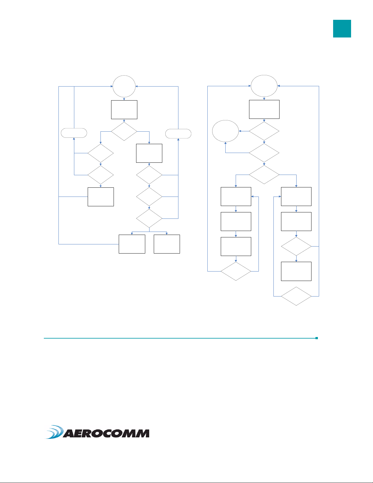
Figure 1: Pending RF and Data in Buffer Flow
11
Discard Packet
Yes
Send Packet over
Receive full
packet and
check CRC
Yes
Duplicate
Packet
RF
Yes
Receive Mode
Pending RF
Received
Broadcast
Packet
Send Packet over
Addressed Packet
Validate CRC
RF
Matching
Destination
MAC
Yes
Duplicate
Packet
Yes
Acknowledge
Yes
Send RF
Discard Packet
Comm and/Data
Mode
Broadcast Packet
Transmit Packet
Decrement
Broadcast
Attem pts
Receive Mode
Data in B uffe r
Pin 17 Low
AT+++
RF Data
Addressed Packet
Transmit Packet
Receive ACK
Broadcast
Attem pts = 0
Decrement
Tran sm it A ttem pts
Transmit
Attem pts = 0
API CONTROL
API Control is a powerful feature that the Masterless Protocol offers. When enabled, the API Transmit Packet, API
Send Data Complete and API Receive Packet features provide dynamic packet routing and packet accounting ability
to the OEM Host, thereby eliminating the need for extensive programming on the OEM Host side. This ability of the
protocol makes it ideal for any legacy system. API operation utilizes specific packet formats; specifying various vital
parameters used to control radio settings and packet routing on a packet-by-packet basis. The API features can be
used in any combination that suits the OEM’s specific needs.
www.aerocomm.com

THEORY OF OPERATION
12
API Transmit Packet
API Transmit Packet is a powerful command that allows the OEM Host to send data to a single or multiple (broadcast)
transceivers on a packet-by-packet basis. This can be useful for many applications; including polling and/or mesh
networks. Refer to the API Appendix for further details.
API Transmit Packet is enabled when bit-1 of the API Control byte is enabled. The OEM Host should use the following
format to transmit a packet over the RF.
Payload Data
0x81
1 If the OEM Host does not encode the header correctly, the transceiver will send the entire string (up
to 0x80 bytes) and will look for the header in the next data.
2 Although the 7 bytes of overhead are not sent over the RF, they are kept in the buffer until the packet
is sent. Keep this in mind so as not to overrun the 256-byte buffer.
3 Setting the MAC to 0xFF 0xFF 0xFF will broadcast the packet to all available transceivers.
Length
(0x01 - 0x80)
Session
Count
Refresh
Transmit
Retries/Broadcast
Attempts
Destination
MAC (2,1,0)
Payload
Data
API Send Data Complete
API Send Data complete can be used as a software acknowledgement indicator. When a radio sends an addressed
packet, it will look for a received acknowledgement (transparent to OEM Host). If an acknowledgement is not
received, the packet will be retransmitted until one is received or all retries have been used.
For applications where data loss is not an option, the OEM Host may wish to monitor the acknowledgement process
using the API Send Data Complete. If an acknowledgement is not received (Failure), the OEM Host can send the
packet to the transceiver once again.
API Send Data Complete is enabled when bit-2 of the API Control byte is enabled. The transceiver sends the OEM
Host the following data upon receiving an RF acknowledge or exhausting all attempts.
0x82 RSSI RSSI*
1 The RSSI is how strong the remote transceiver heard the local transceiver; RSSI* is how strong the
local transceiver heard the remote transceiver.
2 Successful RF Acknowledge updates the Success/Failure bit.
3 A success will always be displayed when sending broadcast packets after all broadcast attempts
have been exhausted.
0x00: Failure
0x01: Success
API Receive Packet
By default, the source MAC is not included in the received data string sent to the OEM Host. For applications where
multiple radios are sending data, it may be necessary to determine the origin of a specific data packet. When API
Receive Packet is enabled, all packets received by the transceiver will include the MAC address of the source radio as
well as an RSSI indicator which can be used to determine the link quality between the two.
API Receive Packet is enabled when bit-0 of the API Control byte is enabled. Upon receiving a packet the radio sends
its OEM Host the packet in the following format:
0x81
Payload Data
Length
(0x01 - 0x80)
RSSI RSSI*
Source MAC
(2,1,0)
Payload
Data

THEORY OF OPERATION
ENGINEER’S TIP
When both API Send Data Complete and API Receive Packet are enabled, the Send Data
Complete will be received before the transceiver sees the Receive API Packet. This order may
get reversed when the API Send Data Complete is missed and is being resent after the API
Receive Packet is received.
13
www.aerocomm.com
SERIAL INTERFACE
In order for the OEM Host and a transceiver to communicate over the serial interface they need to have the same
serial data rate. Refer to the following sections to ensure that the OEM Host data rate matches the serial interface
baud rate.
SERIAL COMMUNICATIONS
The AC4790 is a TTL device which can be interfaced to a compatible UART (microcontroller) or level translator to allow
connection to serial devices. UART stands for Universal Asynchronous Receiver Transmitter and its main function is
to transmit or receive serial data.
Asynchronous Operation
Since there is no seperate clock in asynchronous operation, the receiver needs a method of synchronizing with the
transmitter. This is achieved by having a fixed baud rate and by using START and STOP bits. A typical asynchronous
mode signal is shown below.
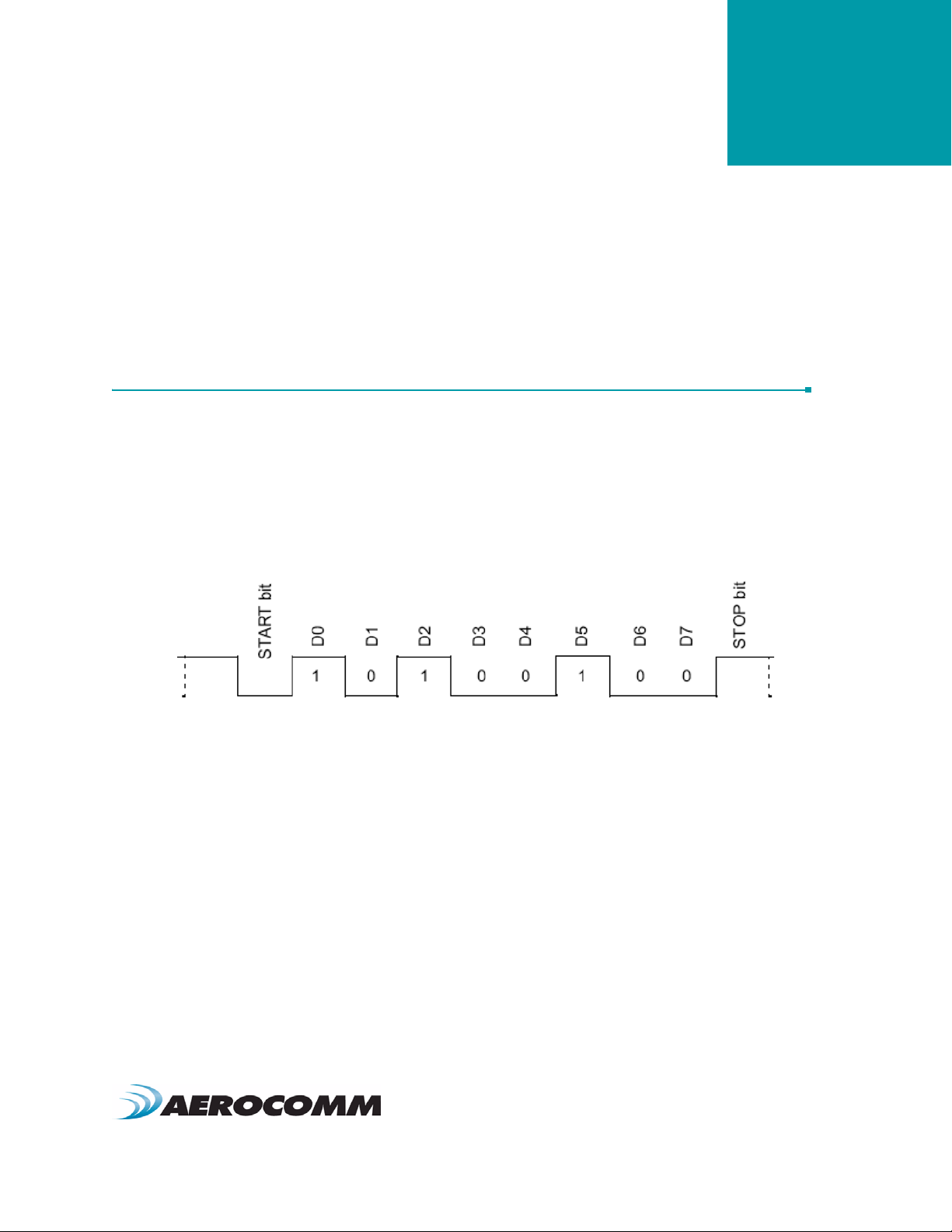
Figure 2: Asynchronous Mode Signal
4
The UART outputs and inputs logic level signals on the TX and RX pins. The signal is high when no data is being
transmitted and goes low when transmission begins.
The signal stays low for the duration of the START bit and is followed by the data bits; LSB first. The STOP bit follows
the last data bit and is always high. After the STOP bit has completed, the START bit of the next transmission can
occur.
Parity
A parity bit is used to provide error checking for a single bit error. When a single bit is used, parity can be either even
or odd. Even parity means that the number of ones in the data and parity sum to an even number and vice-versa. The
ninth data bit can be used as a parity bit if the data format requires eight data bits and a parity bit as shown below.
www.aerocomm.com
 Loading...