

AERO 8000 H-PC Service Manual

Please check out our eBay auctions for more great
deals on Factory Service Manuals:

Notice
The information in this guide is subject to change without notice.
COMPAQ COMPUTER CORPORATION SHALL NOT BE LIABLE
FOR TECHNICAL OR EDITORIAL ERRORS OR OMISSIONS
CONTAINED HEREIN; NOR FOR INCIDENTAL OR
CONSEQUENTIAL DAMAGES RESULTING FROM THE
FURNISHING, PERFORMANCE, OR USE OF THIS MATERIAL.
This guide contains information protected by copyright. No part of this
guide may be photocopied or reproduced in any form without prior
written consent from Compaq Computer Corporation.
1999 Compaq Computer Corporation. All rights reserved. Printed in
the U.S.A.
COMPAQ, AERO, and the Compaq logo are registered in the U. S.
Patent and Trademark Office.
Microsoft, MS-DOS, Windows, Windows NT, and other names of
Microsoft Products referenced herein are trademarks or registered
trademarks of Microsoft Corporation.
Product names mentioned herein may be trademarks and/or registered
trademarks of their respective companies.
Maintenance & Service Guide
Compaq Aero 8000 H/PC Pro
First Edition (May 1999)
Compaq Computer Corporation
preface
This Maintenance & Service Guide is a troubleshooting guide that can be used for reference when
servicing the Compaq Aero 8000 H/PC Professional. Only authorized technicians trained by
Compaq should attempt to repair this equipment.
Compaq Computer Corporation reserves the right to make changes to the Compaq Aero 8000
H/PC without notice.
Symbols and Conventions
The following words and symbols mark special messages throughout this guide:
WARNING:
warning could result in bodily harm or loss of life.
!
CAUTION:
result in damage to equipment or loss of data.
Text set off in this manner presents commentary, sidelights, clarifying information, or
✎
specific instructions.
Technician Notes
WARNING:
equipment. All troubleshooting and repair procedures are detailed to allow only
!
subassembly/module level repair. Because of the complexity of the individual
components and subassemblies, no one should attempt to make repairs at the component
level or to make modifications to any printed wiring board. Improper repairs can create
a safety hazard. Any indications of component replacement or printed wiring board
modifications may void any warranty.
CAUTION:
proper operation, plug the AC power cord into a properly grounded AC outlet only.
Text set off in this manner indicates that failure to follow directions in the
Text set off in this manner indicates that failure to follow directions could
Only authorized technicians trained by Compaq should attempt to repair this
The Aero 8000 H/PC Pro is designed to be electrically grounded. To ensure
System Serial Number
The serial number is displayed on the underside of the Aero 8000 H/PC Pro.
Preface v

Locating Additional Information
The following documentation is available to support the Compaq Aero 8000 H/PC Pro:
„#Reference Guide (online)
„#Compaq Service Advisories and Bulletins
„#Compaq QuickFind
„#Compaq Service Quick Reference Guide
vi Preface

chapter
1
EMOVAL AND REPLACEMENT
R
ROCEDURES
P
This chapter provides removal and replacement assembly procedures for the Compaq Aero 8000
H/PC Professional.
1.1 Electrostatic Discharge
A discharge of static electricity from your body or other conductor may damage system boards or
other electrostatic-sensitive devices. This type of damage may reduce the life expectancy of the
devices.
1.1.1 Preventing Electrostatic Discharge
To prevent electrostatic damage, observe the following precautions:
„#Avoid hand contact by transporting and storing products in electrostatic-safe containers.
„#Keep electrostatic-sensitive parts in their containers until they arrive at electrostatic-free
workstations.
„#Place parts on a grounded surface before removing them from their containers.
„#Avoid touching pins, leads, or circuitry.
„#Always be properly grounded when touching an electrostatic-sensitive component or
assembly.
1.1.2 Grounding Methods
There are several methods for grounding. Use one or more of the following methods when handling
or installing electrostatic-sensitive parts.
„#Use a wrist strap connected by a ground cord to a grounded workstation or computer chassis.
Wrist straps are flexible straps with a minimum of 1 megohm +/- 10 percent resistance in the
ground cords. To provide proper ground, wear the strap snug against the skin.
„#Use heel straps, toe straps, or boot straps at standing workstations. Wear the straps on both
feet when standing on conductive floors or dissipating floor mats.
„#Use conductive field service tools.
„#Use a portable field service kit with a folding, electrostatic-dissipating work mat.
If you do not have the suggested equipment for proper grounding, or if you need more
✎
information on static electricity or assistance with product installation, contact a Compaq
authorized service provider.
Removal and Replacement Procedures 1-1
1.2 Service Considerations
Listed below are some of the considerations that you should keep in mind during the disassembly
and assembly of the Compaq Aero 8000 H/PC Pro.
1.2.1 Tool and Software Requirements
To service the Aero 8000, you need the following:
„#Magnetic screwdriver
„#Torx T-8 screwdriver
„#Small Phillips or flat blade screwdriver
1.2.2 Screws
The screws used in the Compaq Aero 8000 H/PC Pro are not interchangeable. If an incorrect screw
is used during the reassembly process, it can damage the unit. Compaq strongly recommends that all
screws removed during disassembly be kept with the part that was removed, then returned to their
proper locations.
When servicing the computer, ensure that all screws are kept with the part with
CAUTION:
which they belong. Using an improper screw during reassembly can damage the computer.
IMPORTANT:
work area to prevent damage.
As each subassembly is removed from the computer, it should be placed away from the
1.2.3 Cables and Connectors
Cables must be handled with extreme care to avoid damage. Apply only the tension required to seat
or unseat the cables during insertion or removal from the connector. Handle cables by the connector
whenever possible. In all cases, avoid bending, twisting. Or tearing the cables, and ensure that the
cables are routed in such a way that they cannot be caught or snagged by parts being removed or
replaced. Handle flex cables with extreme care; they can tear easily.
When servicing the computer, ensure that cables are placed in their proper
CAUTION:
location during the reassembly process. Improper cable placement can damage the
computer.
1.2.4 Plastic Parts
Plastic parts can be damaged by the use of excessive force during disassembly and reassembly.
When handling the plastic parts, use care. Use a bezel removal tool to separate plastic components.
Apply pressure only at the points designated in the maintenance instructions.
1-2 Removal and Replacement Procedures

1.3 Serial Number
The Aero 8000 H/PC Pro serial number should be given to Compaq when requesting information or
ordering spare parts. The serial number is displayed on the bottom of the device.
Removal and Replacement Procedures 1-3

1.4 Features
„#Full-size 800 x 600 SVGA viewable area display
„#Light-weight (2.9 lbs./1.32 kgs.) and slim (8.5 x 10.9 x 9.8”/21.6 x 27.7 x 24.9cm) design
allows for convenient mobile transport
„#Long battery life due to lower power requirements than a notebook
„#Automatic synchronization keeps the Aero 8000 and desktop PC up-to-date
„#Plugs into a standard VGA connector; does not require a special video adapter card
„#Windows CE platform provides handheld versions of Word, Excel, PowerPoint, Outlook and
Access
„#Large keyboard and convenient touchpad mouse have a definite advantage over most
handheld PCs
„#Built-in 56K V.90 modem provides instant connectivity
„#Enhanced security features allow use of a Smart Card for internal security, and a lock slot to
prevent unit theft
„#Extensive I/O options:
❏
Type II PC Card slot
❏
Type II CompactFlash slot
❏
Serial port
❏
Infrared
❏
PS/2 port
❏
Two-way microphone/speaker
1-4 Removal and Replacement Procedures
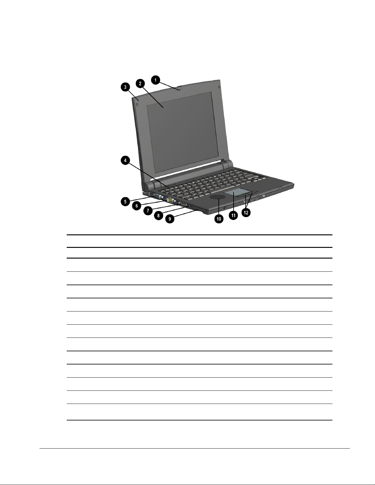
1.5 Front and Left Side Components
The components located on the Aero 8000 front and left side assembly are identified below.
Front and Left Side Components
Front and Left Side Components
No. Component Function
1
2
3
4
5
6
7
8
9
q
w
Lid Latch Secures the lid when the unit is closed.
Screen Displays on-screen information.
Microphone Allows voice memo recording. Works whether the device is open or closed.
Power Button Powers the device. Press once to turn on the device. Press again to turn off.
VGA Port Accepts a VGA video cable.
Serial Port Connects serial devices such as a printer cable.
Sync Port Connects the auto-sync cable for connection to a desktop or docking station.
AC Power Connector Connects to external (AC) power via the AC adapter.
CompactFlash Slot Accepts a Type I or Type II CompactFlash card.
Speaker Produces sound for the alarm, playback of voice memos, and other audio effects.
Touch Pad Manipulates the cursor. Press and move your finger on the pad.
Mouse Buttons Activates the corresponding cursor command. Use like left and right buttons on a
full-size mouse.
Removal and Replacement Procedures 1-5
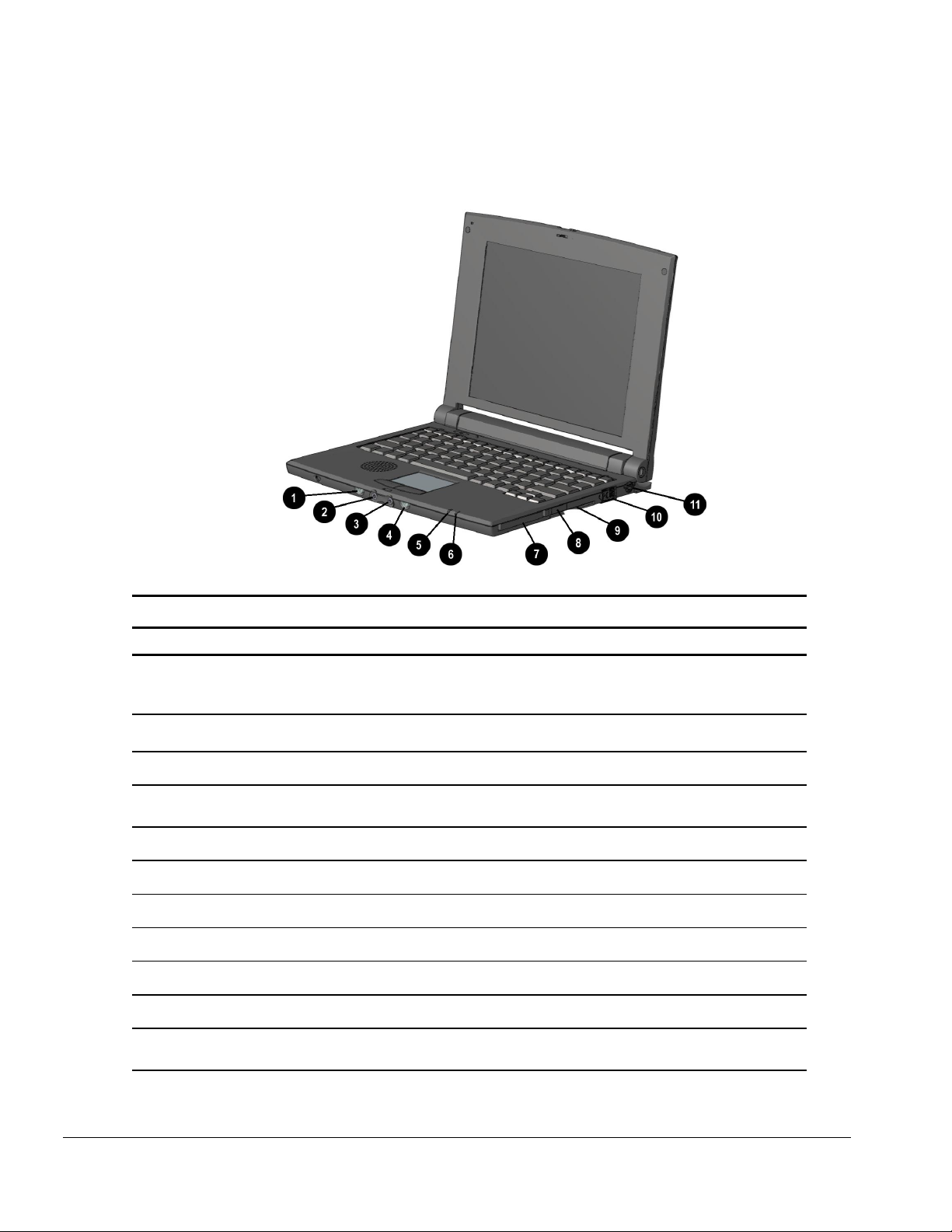
1.6 Front and Right Side Components
The components located on the Aero 8000 front and right side assembly are identified below.
Front and Right Side Components
Front and Right Side Components
No. Component Function
1
2
3
4
5
6
7
8
9
q
Notification Button/LED Notifies the user that the device is powered on or an alarm activates.
Flashes once when the device is turned on. Flashes continuously
when an alarm you have set goes off. Press once to stop the alarm.
Audio In Accepts audio input for recording or playback.
Audio Out Distributes audio output.
Record Button/LED Activates record function. Press once to record. Press again to stop
recording.
Power On LED Appears when the unit is connected to AC power.
Battery Charge LED Appears when the unit is charging.
PC Card Slot Accepts a Type I or Type II PC card.
Infrared (IR) Port Allows for wireless infrared communication.
Smart Card Slot Accepts a credit card-sized Smart Card.
Modem Port Connects an RJ-11 modem cable.
PS/2 Port Allows for connection of up to 2 PS/2 devices, such as a keyboard and
mouse using an optional “Y” cable.
1-6 Removal and Replacement Procedures
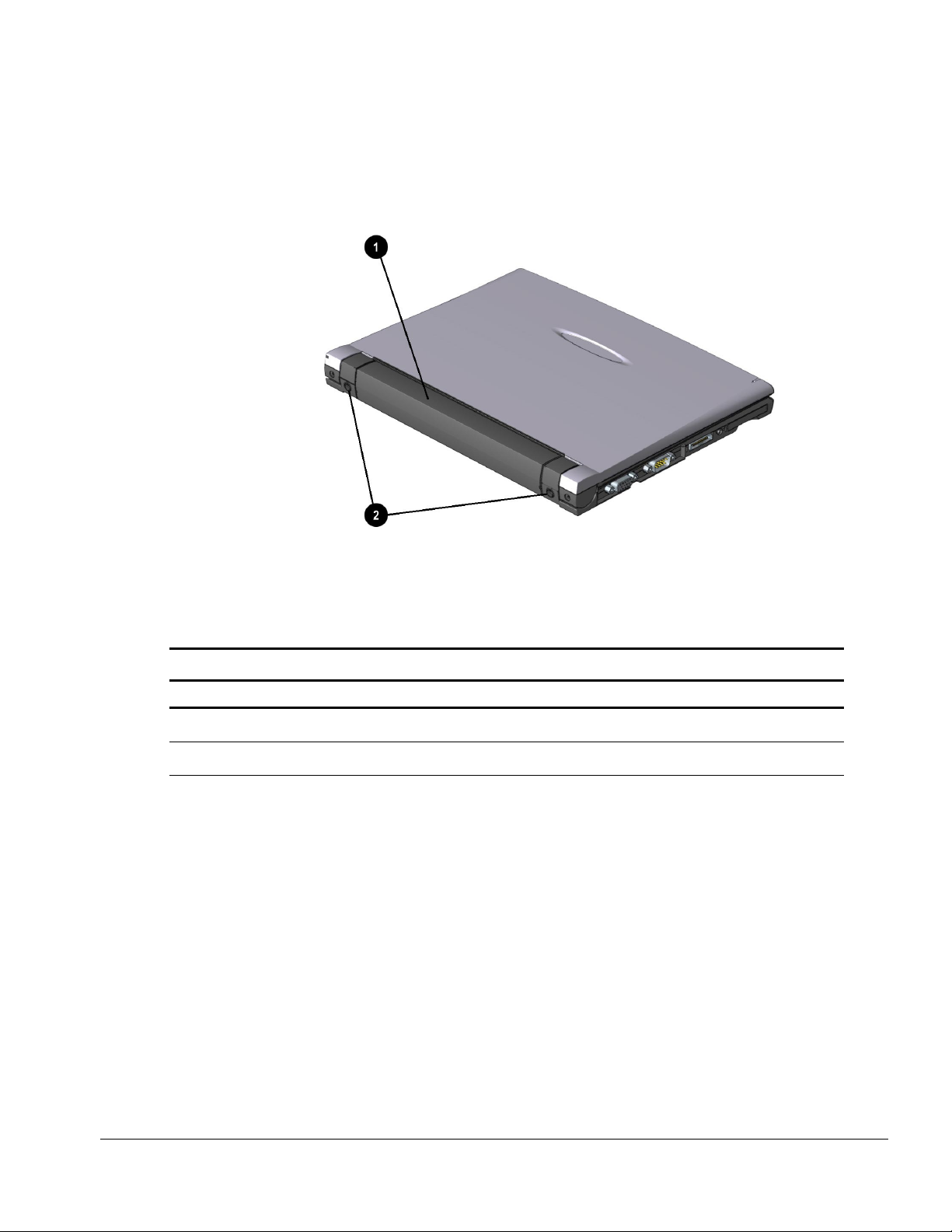
1.7 Top and Rear Components
The components located on the Aero 8000 top and rear assembly are identified below.
Top and Rear Components
Top and Rear Components
No. Component Function
1
2
Battery Pack Powers the device as a rechargeable lithium-ion (Li-Ion) battery pack.
Strap Inserts Allows for connection of a shoulder strap for easier carrying.
Removal and Replacement Procedures 1-7
 Loading...