

Page 1

TECHNICAL MANUAL
VEC
COANDA EFFECT FAN COIL
IVECTY
0906
5074502_01
Replace : 5074502_00 / 0904
Page 2

Page 3

3
English
DECLARATION OF CONFORMITY
Transport • Safety symbols
Important information
Description • Versions
Description of components • Selection criteria
System configuration
Technical data
Operating limits
Cooling capacity
Heating capacity (3R)
Heating capacity BV (1R)
Coil pressure drops
Correction factors in operation using glycol water
Capacity and sound pressure
Accessories
Installation
Size data
Wiring diagrams
Troubleshooting • Maintenance
INDEX
Store the manuals in a dry location to avoid deterioration, as
they must be kept for at least 10 years for any future reference.
Carefully and thoroughly read all the information referred to
in this manual. Pay particular attention to the instructions for
use accompanied by the words “DANGER” or “WARNING”
because, if they are not complied with, the machine/property
can damaged and/or people can be injured.
If any kind of malfunction is not included in this manual, contact the local After Sales Service immediately.
The device must be installed in such a way that maintenance
and/or repair operations are possible.
The device warranty does not in any case cover costs due to
automatic ladders, scaffolding or other lifting systems
necessa-
ry for carrying out repairs under guarantee.
The normal wear of the components and filter is not covered
by the warranty.
AERMEC S.p.A. declines all liability
for any damage due to
improper use of the machine, or the partial or superficial reading of the information contained in this manual.
This manual contains the following number of pages: 40
REMARKS
4
5
6
7
8
9
10
11
12
16
17
18
19
20
21
26
27
28
38
Page 4

4
VEC
Bevilacqua, 02/03/2009 La Direzione Commerciale – Sales and Marketing Director
Luigi Zucchi
AERMEC S.p.A.
I-37040 Bevilacqua (VR) Italia – Via Roma, 996
Tel. (+39) 0442 633111
Telefax (+39) 0442 93730 – (+39) 0442 93566
www .aermec. com - info @aermec. com
DICHIARAZIONE DI CONFORMITÀ
Noi, fi rmatari della presente, dichiariamo sotto la nostra esclusiva
responsabilità, che il prodotto:
VENTILCONVETTORE
serie VEC
al quale questa dichiarazione si riferisce è conforme alle seguenti norme
armonizzate:
- CEI EN 60335-2-40
- CEI EN 55014-1
- CEI EN 55014-2
- CEI EN 61000-6-1
- CEI EN 61000-6-3
soddisfando così i requisiti essenziali delle seguenti direttive:
- Direttiva LVD 2006/95/CE
- Direttiva compatibilità elettromagnetica 2004/108/CE
VEC APC CON ACCESSORI
E’ fatto divieto di mettere in servizio il prodotto dotato di accessori
non di fornitura Aermec.
CONFORMITY DECLARATION
We the undersigned declare, under our own exclusive responsibility,
that the product:
FAN COIL
VEC series
to which this declaration refers, complies with the following standardised
regulations:
- EN 60335-2-40
- EN 55014-1
- EN 55014-2
- EN 61000-6-1
- EN 61000-6-3
thus meeting the essential requisites of the following directives:
- Directive LVD 2006/95/CE
- EMC Electromagnetic Compatibility Directive 2004/108/CE
VEC APC WITH ACCESSORIES
It is not allowed to use the unit equipped with accessories not supplied by Aermec.
CERTIFICAT DE CONFORMITÉ
Nous soussignés déclarons sous notre exclusive responsabilité que le
produit:
VENTILO-CONVECTEURS
série VEC
auquel cette déclaration fait référence, est conforme aux normes
harmonisées suivantes:
- EN 60335-2-40
- EN 55014-1
- EN 55014-2
- EN 61000-6-1
- EN 61000-6-3
satisfaisant ainsi aux conditions essentielles des directives suivantes:
- Directive LVD 2006/95/CE
- Directive compatibilité électromagnétique 2004/108/CE
VEC APC PLUS ACCESSOIRES
Il est interdit de faire fonctionner l'appareil avec des accessoires qui ne
sont pas fournis de Aermec.
KONFORMITÄTSERKLÄRUNG
Wir, die hier Unterzeichnenden, erklären auf unsere ausschließlich
Verantwortung, dass das Produkt:
GEBLÄSEKONVEKTOR
der Serie VEC
auf das sich diese Erklärung bezieht, den folgenden harmonisierten
Normen entspricht:
- EN 60335-2-40
- EN 55014-1
- EN 55014-2
- EN 61000-6-1
- EN 61000-6-3
womit die grundlegenden Anforderungen folgender Richtlinien erfüllt
werden:
- Richtlinie LVD 2006/95/CE
- Richtlinie zur elektromagnetischen Verträglichkeit 2004/108/CE
VEC APC + ZUBEHÖR
Falls das Gerät mit Zubehörteilen ausgerüstet wird, die nicht von
Aermec geliefert werden, ist dessen Inbetriebnahme solange untersagt.
DECLARACIÓN DE CONFORMIDAD
Los que suscriben la presente declaran bajo la propia y exclusiva
responsabilidad que el conjunto en objeto, defi nido como sigue:
FAN COIL
serie VEC
al que esta declaración se refi ere, está en conformidad a las siguientes
normas armonizadas:
- EN 60335-2-40
- EN 55014-1
- EN 55014-2
- EN 61000-6-1
- EN 61000-6-3
al que esta declaración se refi ere, está en conformidad a las siguientes
normas armonizadas:
- Directiva LVD 2006/95/CE
- Directiva compatibilidad electromagnétic 2004/108/CE
VEC APC CON ACCESORIOS
Está prohibido poner en marcha el producto con accesorios
no suministrados por Aermec.
Page 5

5
1
2
3
4
5
6
35Kg
NON bagnare • Do NOT wet
CRAINT l’humidité • Vor Nässe schützen
NO mojar
NON lasciare gli imballi sciolti durante il trasporto.
Do NOT leave loose packages during transport.
ATTACHER les emballages pendant le transport.
Die Verpackungen nicht ungesichert transportieren.
NO lleve las cajas sueltas durante el transporte.
Sovrapponibilità: controllare sull’imballo la posizione della freccia per
conoscere il numero di macchine impilabili.
Stacking: control the packing for the arrow position to know the num-
ber of machines that can be stacked.
Empilement: vérifier sur l’emballage la position de la flèche pour con-
naître le nombre d’appareils pouvant être empilés.
Stapelung: Anhand der Position des Pfeiles an der Verpackung kontrol-
lieren, wieviele Geräte stapelbar sind.
Apilamiento: observe en el embalaje la posición de la flecha para saber
cuántos equipos pueden apilarse.
NON calpestare • Do NOT trample
NE PAS marcher sur cet emballage • Nicht betreten
NO pisar
NON trasportare la macchina da soli se il suo peso supera i 35 Kg.
DO NOT handle the machine alone if its weight is over 35 Kg.
NE PAS transporter tout seul l’appareil si son poids dépasse 35 Kg.
Das Gerät NICHT alleine tragen, wenn sein Gewicht 35 Kg überschreitet.
NO maneje los equipos en solitario si pesan más de 35 kg.
Pericolo: Pericolo: Pericolo!!!
Tensione Organi in movimento
Danger: Danger: Danger!!!
Power supply Movings parts
Danger: Danger: Danger!!!
Tension Organes en mouvement
Gefahr ! Gefahr ! Gefahr!!!
Spannung Rotierende Teile
Peligro: Peligro: Peligro!!!
Tensión Elementos en movimiento
TRASPORTO • CARRIAGE • TRANSPORT • TRANSPORT • TRANSPORTE
SIMBOLI DI SICUREZZA • SAFETY SYMBOL • SIMBOLES DE SECURITE
SICHERHEITSSYMBOLE • SÍMBOLOS DE SEGURIDAD
Page 6

6
English
The fan coils are shipped in standard package which consists of expanded polystyrene foam and cardboard shells.
PACKAGING
Consult control panel manual for installation and use instructions.
USE
WARNING: electrical wirings, installation of the fan coils and relevant accessories should be performed by a technician who has the necessary technical
and professional expertise to install,
modify, extend and maintain systems,
and who is able to check the systems
for the purposes of safety and correct
operation.
WARNING: the fan coil is connected to
the power supply and a water circuit.
Any operation by persons who do not
possess the required technical skills can
lead to personal injury to the operator
or damage to the unit and surrounding
objects.
WARNING:before carrying out any
work, wear the proper personal protective equipment.
WARNING: the appliance must be fitted
according to the national regulations on
process plant engineering.
WARNING: check that the power supply is disconnected before carrying out
any procedures on the unit.
WARNING: install a device, main
switch or plug which allows to completely cut off the power supply from the
unit.
WARNING! DANGER! Any use of the
unit not expressly indicated by Aermec
is strictly prohibited.
MALFUNCTIONS
In the event of a malfunction, cut off
power supply to the unit, then restore
the power and start the unit again. If
the problem occurs again, call the local
After-Sales Service immediately.
POWER THE FAN COIL ONLY WITH
230 VOLT, SINGLE PHASE, 50 Hz
Any other type of power supply could
permanently damage the fan coil.
DO NOT TUG THE ELECTRIC CABLE
It is very dangerous to pull, tread on or
crush the electric power cable, or fix it
with nails or drawing pins.
A damaged power cable can cause short
circuits and injure people.
DO NOT OBSTRUCT THE AIR
OUTLETS BY PLACING OBJECTS INTO
THEM
Do not put anything in the air outlet
slots.
This could injure people and damage
the fan.
DO NOT USE THE FAN COIL
IMPROPERLY
Do not use the fan coil for animal
husbandry applications (e.g. incubation).
AIR THE ROOM
Periodically air the room in which
the fan coil has been installed. This is
particularly important if the room is
occupied by many people, or if gas
appliances or sources of odours are
present.
ADJUST TEMPERATURE ADEQUATELY
The room temperature should be
adjusted in order to provide maximum
comfort to the people in the room,
especially if they are elderly, children
or sick people; avoid differences over
7°C between the outdoor temperature
and the temperature inside the room in
summer.
Carefully choose the room temperature
so as to save energy.
CORRECT AIR JET AIMING
ADJUSTMENT
Air coming out from the fan coil must
not reach people directly; in fact, even
if the air is warmer than the room
temperature, it could cause a cold
sensation and result in discomfort.
DO NOT USE EXCESSIVELY HOT
WATER
To clean the indoor unit, use soft cloths
or sponges dampened with water at a
maximum of 40°C. Do not use chemical
products or solvents to clean any part of
the fan coil. Do not spray water on the
outer or inner surfaces of the fan coil (it
might cause short circuits).
CLEAN THE FILTER FREQUENTLY
Cleaning the filter frequently guarantees
enhanced operating efficiency.
Check whether the filter is very dirty: if it
is, clean it more often.
Clean frequently; remove the accumulated dust with a vacuum cleaner.
Once the filter is clean, refit it to the fan
coil following the removal instructions
but in reverse order.
The normal wear and tear of germicidal
lamps and filter is not covered by the
warranty.
SUPPLEMENTARY CLEANING
The possibility to remove the basin and
the shrouds of the examinable fans (done
only by suitably trained and qualified
personnel) allows to thoroughly clean
even the internal parts - an essential condition when the unit is installed in very
crowded areas or places requiring high
standards of hygiene.
WHAT IS NORMAL
In the cooling function, water vapour
may be present in the air delivery of the
fan coil.
In the heating function, a slight hiss
might be heard close to the fan coil.
Sometimes the fan coil might give off
unpleasant smells due to the accumulation of substances present in the air
of the room (clean the filter more often,
especially if the room is not ventilated
regularly).
While the unit is functioning, there
could be noises and creaks inside
the device due to the various thermal
expansions of the elements (plastic and
metal), but this does not indicate any
malfunction and does not damage the
unit unless the maximum input water
temperature is exceeded.
IMPORTANT INFORMATION
Page 7

7
English
Fan coil for treating air both in winter and summer.
The air is distributed throughout the room via outlets which, thanks to the COANDA effect, draw the air jet towards the ceiling.
Install the unit on the suspended ceiling.
AVAILABLE VERSIONS AND SIZES
VEC fan coils are available in:
4 sizes with a 3 -row coil compulsory accessory
VEC 20 VEC 20 GL
VEC 30 VEC 30 GL
VEC 40 VEC 40 GL
VEC 50 VEC 40 GL
DESCRIPTION OF THE UNIT
VEC 20
VEC 20 GL
System types
The VEC fan
coils are designed for systems with 2 and 4 pipes, in the versions:
- without valve;
- with 3-way water valve
(VCF);
- with 2-way water valve for variable flow rate systems (VCFD);
- with electric heater (RX);
- with electric heater (RX) and valve (VCF/VCFD);
- with hot water coil for systems with 4 pipes (BV) and 2 valves (VCF/VCFD).
Each configuration requires a control panel that manages the functions and accessories installed.
Page 8

8
English
CON TROL PA NEL
The control panel (accessory) can only
be installed on the wall.
The AERMEC fan coil versions without
a control panel can all be combined
with the HSH AERDOMUS centralised
control system, using wired or wireless
connections.
Consult the control panel characteristics before selecting a panel.
ELECTRIC FAN ASSEMBLY
This consists of double suction centrifugal fans with lengthways blades to
obtain a high air flow with a low number of revs. The electrical motor, protected against overloading, has three speeds with the running capacitor always
on, directly coupled with the fans and
cushioned with flexible supports.
BEARING STRUCTURE
Made of galvanised sheet metal of an
adequate thickness. Hole in the back
for wall mounting. A fan cover panel is
available for front-mounted ceiling units.
Each unit is equipped with a condensate
collection tray.
CONDENSATE DRAIN
Every device is fitted with a tray for collecting condensation, with a connection
for draining condensation produced by
the unit in cooling mode. When there
are differences in levels, it is possible
to apply the accessory (DSC4) outside
the unit, complete with pump and water
level control device.
PLUMBING CONNECTIONS
The connections, located on the left
hand side, are female. The coil may also
be rotated.
DESCRIPTION OF COMPONENTS
SELECTION CRITERIA
The Coanda effect fan coil of the VEC
range must be installed in suspended
ceilings and is completed with the obligatory accessory VEC20GL.
The accessory VEC20GL consists of
the panel with suction from below and
delivery with adjustable diffusers that
allow the air to be distributed throughout the room, taking advantage of the
COANDA effect.
VEC must be combined with a control panel to be mounted on the wall.
Consult the characteristics and compatibility of the control panels supplied as
an accessory.
Some control panels can control a
network of fan coils if they are used in
combination with the interface cards
SIT3 and SIT5 supplied as accessories.
The AERMEC fan coil versions without
a control panel can all be combined
with the HSH AERDOMUS centralised
control system, using wired or wireless
connections.
The main technical data of the VEC fan
coils are summarised in the tables.
The table shows the sensible and total
refrigerating yield at maximum speed,
on the basis of the inlet water temperature, its temperature change, and the
dry bulb and wet bulb air temperature,
for sensitive yield and total yield respectively, for versions with a 3-row coil.
Performance levels at average and minimum speed are obtained by multiplying
the values by the correction factors indicated.
The water side pressure drops are
shown in the diagrams.
The correction factors when the unit
operates with glycol water for cooling
and heating function modes are shown
in the graphs in percentages of glycol of
10%, 20% and 35%.
The heating capacity yield, on the
basis of the water flow rate and the
difference in temperature between the
incoming water and the incoming air, is
represented in a graph and refers to the
maximum speed. Performance levels at
average and minimum speed are obtained by multiplying the values shown on
the graph (at maximum speed) by the
correction factors indicated.
The pressure level and sound output
of the fan coils at the various speeds are
shown in the tables.
The installation information is included in the manuals supplied together
with each fan coil or its accessory. This
manual is limited to provide general
information in order to obtain a correct
installation; it also contains drawings
with fan coil dimensions and the wiring
diagrams with the connections to control panels.
Page 9

9
English
System with 2 pipes, with water sensor
SW Water temperature sensor
VCF Solenoid valve (Heating / Cooling)
VC Solenoid valve (Heating)
VF Solenoid valve (Cooling)
SA Room temperature sensor
V3,V2,V1 Maximum, Average or Minimum fan speed
RX Electric heater
CONFIGURATIONS FOR SYSTEMS WITH VEC
System with 2 pipes, without water sensor
System with 4 pipes, with water sensor System with 4 pipes, without water sensor
Key:
Page 10

10
English
TECHNICAL DATA
Performance values refer to the following conditions:
Sound pressure measured in semi-reverberating chamber, 85m3,
and with reverberation time Tr = 0.5s.
Cooling:
- room air temperature 27°C D.B., 19°C W.B.;
• maximum speed:
- water inlet temperature 7°C; Δt water 5°C.
• average and minimum speed:
- water inlet temperature 7°C;
- water flow rate as at maximum speed.
Heating:
room air temperature 20°C D.B.;
• maximum speed:
- water inlet temperature 50°C; Δt water 10°C.
- water flow rate as for cooling operation.
• average and minimum speed:
- water inlet temperature 50°C;
- water flow rate as at maximum speed.
Mod.
Heating
Heating capacity
Electric heater heating capacity
Cooling
Total cooling capacity
Sensible cooling capacity
Water flow rate
Water pressure drop
air flow rate
Number of fans
Sound pressure
Sound power
Water contents
Max. motor power
Max. input current
Max. motor power
with electric heater
Input current
with electric heater
Coil connections 3R
Coil connections 1R
Power supply
VEC with a 3-row coil
VEC 20 VEC 30 VEC 40 VEC 50
W (max) 1835 2770 3745 4285
W (med) 1505 2340 3105 3785
W (min) 1105 1950 2505 2840
W 950 1300 1650 1950
W (max) 1320 1950 2985 3610
W (med) 1085 1645 2470 3170
W (min) 805 1370 1985 2350
W (max) 1085 1535 2410 2595
W (med) 885 1285 1980 2275
W (min) 640 1055 1580 1680
l/h 227 335 514 621
kPa 4,6 13,3 11,3 14,8
m
3
/h (max) 247 383 511 613
m
3
/h (med) 194 309 406 529
m
3
/h (min) 130 241 306 371
n. 1 2 2 2
dB (A) (max) 39,5 36,5 40,0 44,5
dB (A) (med) 33,5 31,5 34,5 41,5
dB (A) (min) 26,5 26,5 29,5 34,5
dB (A) (max) 48,0 45,0 48,5 53,0
dB (A) (med) 42,0 40,0 43,0 50,0
dB (A) (min) 35,0 35,0 38,0 43,0
l 0,79 1,11 1,48 1,48
W 25 44 57 67
A 0,12 0,21 0,28 0,35
W
975 1344 1707 2017
A
4,25 5,86 7,45 8,83
ø 1/2" 1/2" 3/4" 3/4"
ø 1/2" 1/2" 1/2" 1/2"
230V ~ 50Hz
Page 11

11
English
MINIMUM AVERAGE WATER TEMPERATURE
Temperature of the air in the room with dry bulb °C
21 23 25 27 29 31
15 3 3 3 3 3 3
Temperature of the air in the room 17 3 3 3 3 3 3
with wet bulb °C 19 3 3 3 3 3 3
21 6 5 4 3 3 3
23 - 8 7 6 5 5
If the fan coil is working in cold
continuous mode inside an environment
where the relative humidity is high,
condensate might form on the air
delivery. This condensate might be
deposited on any objects underneath
and on the floor.
To avoid condensate on the external
structure of the device while the fan is
functioning, the average temperature of
the water must not be lower than the
limits shown in the table below, that
depend on the thermo-hygrometric conditions of the air in the room.
The limits mentioned above refer to
operation while the fan is set
to its minimum speed level.
In the event of prolonged fan inactivity
and with cold water passing through the
coil, condensate may form on the external case of the unit. As a result, we rec-
ommend including the three-way valve
accessory.
OPERATING LIMITS
In order to prevent air stratification
in the room, and therefore to achieve
improved mixing, it is obligatory not
to supply the fan coil with water at a
temperature over 65°C.
The use of water at high temperatures
could cause squeaking due to the
different thermal expansions of the
elements (plastic and metal), this does
not however cause damage to the unit if
the maximum operating temperature is
not exceeded.
Maximum water input temperature ........................... 65°C
Maximum operating pressure ..................................... 8 bar
Operating voltage ..............................230V(±10%) ~ 50Hz
Room temperature .................................................. 0-40°C
Air humidity ..................................................... <85% U.R.
Output limits (3-row coil):
MOD. VEC 20 30 40 50
Minimum output [l/h] 100 100 150 150
Maximum output [l/h] 750 750 1100 1100
Minimum average water temperature
Water temperature
Page 12

12
English
COOLING CAPACITY
The cooling capacities yielded shown in the table must be multiplied by the following factors:
MOD. VEC 20
Maximum speed
total power
1.00
sensible power
1.00
Average speed
total power
0.82
sensible power
0.82
Minimum speed
total power
0.61
sensible power
0.59
VEC20 TOTAL COOLING CAPACITY [W] SENSIBLE COOLING CAPACITY [W]
Water temp. °C Wet bulb air temperature [°C] Dry bulb air temperature [°C]
Inlet t 15 17 19 21 23 21 23 25 27 29 31
5
3 1089 1523 1984 – – 932 1096 1255 1391 1525 1655
4 977 1390 1839 2299 2783 851 1017 1181 1323 1460 1595
5 834 1207 1666 2147 2643 756 917 1082 1251 1395 1532
6 762 1027 1476 1980 2487 712 836 984 1157 1322 1464
7 – 923 1264 1785 2315 672 794 904 1056 1231 1392
6
3 955 1368 1836 2299 – 858 1019 1183 1322 1459 1587
4 847 1221 1687 2147 2635 766 935 1096 1253 1392 1527
5 737 1054 1497 1987 2487 688 836 1000 1167 1325 1463
6 686 893 1301 1815 2323 649 772 908 1075 1244 1395
7 – 832 1097 1594 2144 611 735 848 979 1150 1321
7
3 834 1207 1666 2147 – 774 933 1104 1253 1390 1519
4 740 1062 1513 1987 2479 685 855 1019 1181 1324 1458
5 660 909
1320
1823 2323 629 760 924
1085
1253 1396
6 622 799 1126 1620 2152 589 712 834 997 1160 1324
7 – 745 974 1405 1964 549 670 792 907 1070 1242
8
3 737 1054 1497 1987 – 695 860 1019 1180 1320 1454
4 658 920 1331 1823 2315 613 780 939 1103 1251 1391
5 601 793 1154 1639 2155 568 688 850 1005 1173 1325
6 – 719 985 1430 1976 528 649 772 918 1081 1251
7 – – 875 1223 1757 488 609 734 846 988 1161
9
3 660 909 1344 1823 – 625 779 944 1103 1250 1384
4 590 798 1156 1653 2147 547 694 861 1020 1181 1322
5 542 689 1001 1443 1980 508 627 768 928 1094 1255
6 – 649 850 1250 1777 467 589 711 845 1004 1170
7 – – 782 1054 1551 426 549 670 791 916 1076
10
3 601 793 1154 1639 2155 554 699 863 1018 1179 1317
4 522 700 998 1454 1972 485 622 785 939 1103 1252
5 – 627 860 1261 1793 446 567 691 857 1014 1177
6 – – 755 1075 1566 406 528 648 774 929 1089
7 – – – 926 1357 363 488 609 735 847 1000
11
3 – 688 1001 1443 1980 482 629 781 943 1100 1246
4 – 630 861 1261 1788 425 550 701 863 1021 1180
5 – 568 752 1089 1580 386 507 627 777 934 1096
6 – – 675 934 1368 344 467 589 711 853 1007
7 – – – 821 1170 299 426 549 669 791 926
12
3 – 627 860 1261 1793 409 558 704 865 1017 1175
4 – 561 752 1097 1585 364 485 630 788 941 1102
5 – – 663 944 1376 324 446 567 699 862 1016
6 – – 617 808 1188 282 406 528 648 778 936
7 – – – 739 1006 233 363 488 609 732 852
13
3 – 568 752 1089 1580 343 487 633 784 943 1096
4 – – 671 931 1374 303 424 558 708 865 1019
5 – – 597 810 1188 262 385 506 630 784 936
6 – – – 709 1016 215 344 467 587 711 860
7 – – – – 869 158 299 426 549 669 789
Page 13
13
English
COOLING CAPACITY
The cooling capacities yielded shown in the table must be multiplied by the following factors:
MOD. VEC 30
Maximum speed
total power
1.00
sensible power
1.00
Average speed
total power
0.84
sensible power
0.82
Minimum speed
total power
0.70
sensible power
0.69
VEC30 TOTAL COOLING CAPACITY [W] SENSIBLE COOLING CAPACITY [W]
Water temp. °C Wet bulb air temperature [°C] Dry bulb air temperature [°C]
Inlet t 15 17 19 21 23 21 23 25 27 29 31
5
3 1150 1646 2216 2778 – 995 1200 1414 1594 1758 1916
4 1428 2013 2577 – – 1185 1407 1624 1803 1976 2138
5 1249 1788 2407 3017 – 1080 1303 1535 1731 1909 2080
6 1086 1582 2208 2848 3501 954 1193 1424 1650 1833 2010
7 939 1373 1982 2656 3326 875 1072 1310 1538 1755 1938
6
3 1400 1977 – – – 1182 1397 1606 1780 1947 2113
4 1241 1776 2376 – – 1079 1296 1520 1714 1888 2053
5 1091 1571 2198 2814 3462 967 1198 1424 1638 1821 1993
6 932 1369 1958 2633 3293 854 1084 1310 1539 1745 1924
7 847 1175 1733 2434 3113 795 968 1200 1430 1662 1847
7
3 1203 1755 – – – 1069 1297 1514 1691 1860 2029
4 1063 1551 2167 2769 – 960 1189 1407 1622 1802 1970
5 943 1369
1950
2600 3248 866 1088 1305
1535
1731 1907
6 829 1183 1726 2411 3079 770 977 1208 1430 1653 1833
7 769 1016 1504 2167 2887 717 875 1095 1317 1543 1758
8
3 1036 1520 2120 – – 951 1183 1397 1603 1774 1940
4 932 1344 1935 2554 – 868 1082 1295 1530 1710 1885
5 831 1180 1710 2376 3034 770 977 1203 1425 1639 1817
6 742 1024 1509 2160 2848 689 868 1101 1317 1539 1745
7 – 893 1315 1915 2644 638 795 982 1212 1435 1663
9
3 919 1301 1908 – – 860 1071 1296 1510 1685 1855
4 840 1165 1687 2337 – 773 977 1190 1417 1621 1795
5 744 1016 1489 2129 2808 670 878 1095 1309 1537 1728
6 – 890 1299 1904 2611 610 773 989 1216 1431 1651
7 – 804 1125 1660 2376 557 717 880 1108 1106 1553
10
3 831 1115 1652 – – 767 955 1182 1396 1596 1766
4 747 998 1459 2105 2746 679 875 1088 1308 1529 1709
5 – 895 1277 1864 2571 582 782 995 1207 1424 1635
6 – 794 1121 1645 2365 546 689 884 1110 1327 1539
7 – – 974 1432 2098 475 638 795 1004 1218 1437
11
3 740 966 1412 2047 – 675 862 1074 1293 1505 1679
4 – 889 1253 1834 2516 580 782 973 1192 1417 1617
5 – 802 1110 1616 2326 503 682 886 1100 1318 1534
6 – – 972 1428 2078 449 610 785 1007 1221 1433
7 – – 850 1234 1834 393 557 717 890 1117 1337
12
3 – 875 1203 1796 – 580 772 957 1183 1392 1590
4 – 798 1069 1582 2276 479 687 880 1089 1308 1524
5 – – 959 1397 2044 424 585 791 1001 1210 1423
6 – – 857 1226 1791 368 531 691 896 1117 1331
7 – – – 1067 1579 304 475 638 799 1017 1232
13
3 – 786 1034 1534 – 484 679 866 1061 1291 1499
4 – – 938 1354 2000 396 589 788 977 1192 1412
5 – – 857 1193 1760 343 503 695 894 1105 1318
6 – – – 1057 1548 282 449 610 799 1016 1223
7 – – – 919 1354 209 393 557 717 906 1132
Page 14
14
English
COOLING CAPACITY
The cooling capacities yielded shown in the table must be multiplied by the following factors:
MOD. VEC 40
Maximum speed
total power
1.00
sensible power
1.00
Average speed
total power
0.83
sensible power
0.82
Minimum speed
total power
0.66
sensible power
0.66
VEC40 TOTAL COOLING CAPACITY [W] SENSIBLE COOLING CAPACITY [W]
Water temp. °C Wet bulb air temperature [°C] Dry bulb air temperature [°C]
Inlet t 15 17 19 21 23 21 23 25 27 29 31
5
3 2521 – – – – 2040 2384 2696 2970 3244 –
4 2187 3087 3996 – – 1876 2227 2569 2863 3145 3412
5 1893 2730 3723 4679 – 1677 2036 2403 2737 3028 3310
6 1587 2385 3358 4398 5435 1439 1845 2209 2580 2899 3190
7 1406 2000 2957 4069 5139 1348 1615 2007 2390 2755 3062
6
3 2187 3070 – – – 1861 2220 2548 2829 3102 –
4 1902 2724 3682 – – 1693 2051 2406 2717 3001 3274
5 1650 2397 3364 4357 5378 1490 1871 2230 2586 2884 3168
6 1372 2057 3008 4061 5106 1306 1666 2041 2405 2751 3047
7 1279 1689 2600 3691 4794 1224 1471 1828 2207 2577 2916
7
3 1884 2696 – – – 1684 2040 2384 2686 2963 3233
4 1652 2407 3358 4300 – 1519 1886 2229 2568 2860 3136
5 1423 2085
2985
4020 5049 1330 1697 2046
2410
2736 3026
6 1242 1768 2622 3708 4761 1183 1466 1867 2234 2585 2901
7 1160 1483 2244 3047 4432 1100 1348 1640 2042 2405 2762
8
3 1624 2374 3302 – – 1519 1865 2217 2540 2819 3091
4 1446 2091 2968 3971 – 1366 1701 2058 2405 2714 2994
5 1301 1791 2645 3674 4703 1165 1529 1886 2236 2583 2880
6 1123 1525 2284 3291 4398 1062 1316 1694 2055 2411 2751
7 – 1333 1927 2895 4053 976 1224 1480 1869 2234 2598
9
3 1443 2040 2934 – – 1372 1689 2038 2392 2675 2951
4 1301 1785 2622 3624 – 1212 1531 1891 2230 2564 2853
5 1111 1564 2272 3284 4349 1021 1360 1713 2069 2408 2734
6 – 1330 1960 2895 4028 938 1183 1513 1897 2240 2588
7 – 1217 1632 2499 3607 852 1100 1345 1687 2062 2410
10
3 1301 1751 2578 – – 1221 1525 1864 2214 2531 2807
4 1152 1553 2266 3233 4275 1050 1381 1712 2058 2401 2707
5 – 1372 1972 2883 3979 897 1195 1547 1894 2235 2581
6 – 1185 1689 2499 3607 814 1060 1339 1726 2078 2412
7 – – 1418 2147 3177 726 976 1224 1500 1894 2247
11
3 1159 1516 2210 3183 – 1069 1377 1692 2037 2386 2665
4 – 1386 1927 2849 3905 882 1227 1543 1893 2224 2558
5 – 1222 1692 2504 3585 773 1029 1383 1738 2072 2407
6 – – 1446 2164 3172 688 938 1188 1546 1909 2244
7 – – 1273 1842 2770 597 852 1100 1351 1717 2072
12
3 – 1375 1887 2765 – 914 1229 1531 1865 2208 2517
4 – 1240 1669 2458 3522 734 1071 1395 1732 2057 2393
5 – – 1465 2136 3143 650 897 1224 1567 1901 2236
6 – – 1287 1859 2758 561 814 1059 1374 1746 2083
7 – – – 1571 2379 462 726 976 1224 1544 1911
13
3 – 1234 1624 2397 – 754 1077 1383 1698 2034 2372
4 – – 1465 2085 3104 609 905 1242 1554 1897 2222
5 – – 1319 1847 2724 524 773 1053 1401 1749 2073
6 – – – 1601 2363 429 688 936 1207 1579 1917
7 – – – 1356 2034 313 597 852 1100 1366 1750
Page 15
15
English
COOLING CAPACITY
The cooling capacities yielded shown in the table must be multiplied by the following factors:
MOD. VEC 50
Maximum speed
total power
1.00
sensible power
1.00
Average speed
total power
0.88
sensible power
0.88
Minimum speed
total power
0.65
sensible power
0.65
VEC50 TOTAL COOLING CAPACITY [W] SENSIBLE COOLING CAPACITY [W]
Water temp. °C Wet bulb air temperature [°C] Dry bulb air temperature [°C]
Inlet t 15 17 19 21 23 21 23 25 27 29 31
5
3 3052 ––––2270 2553 2851 3142 – –
4 2780 3670 4711 – – 2129 2431 2720 3028 3318 3602
5 2509 3353 4379 5519 – 1976 2286 2594 2892 3204 3494
6 2230 3029 4018 5179 6420 1785 2134 2449 2755 3066 3370
7 1935 2697 3648 4795 6068 1518 1947 2289 2608 2914 3235
6
3 2731 ––––2118 2412 2693 2991 3279 –
4 2486 3315 4335 – – 1981 2285 2578 2877 3168 3450
5 2244 3014 3987 5135 – 1813 2137 2447 2740 3047 3340
6 1988 2704 3640 4772 6013 1599 1981 2297 2606 2903 3218
7 1709 2403 3285 4379 5640 1330 1776 2137 2457 2763 3076
7
3 2441 3255 – – – 1970 2269 2544 2837 3130 –
4 2222 2976 3942 – – 1821 2138 2430 2715 3015 3303
5 2007 2697
3610
4727 – 1637 1990 2298
2595
2892 3192
6 1777 2418 3271 4341 5596 1400 1820 2148 2455 2752 3063
7 1483 2132 2931 3957 5201 1172 1580 1983 2310 2612 2915
8
3 2184 2909 – – – 1808 2118 2410 2678 2978 3263
4 2003 2652 3557 4644 – 1644 1988 2285 2573 2861 3155
5 1788 2403 3266 4304 5519 1449 1833 2148 2447 2738 3041
6 1565 2150 2923 3927 5157 1182 1637 1996 2306 2600 2904
7 – 1886 2614 3564 4741 – 1368 1818 2159 2469 2764
9
3 1981 2592 3467 – – 1630 1974 2259 2535 2822 3112
4 1807 2365 3188 4229 – 1462 1836 2143 2429 2707 3000
5 1603 2146 2893 3881 5091 1253 1658 2005 2300 2590 2880
6 – 1920 2599 3527 4711 992 1441 1840 2164 2461 2744
7 – 1671 2320 3188 4297 – 1182 1630 2007 2321 2616
10
3 1788 2305 3104 – – 1451 1810 2118 2400 2663 2959
4 1615 2116 2825 3821 – 1277 1658 1996 2287 2566 2847
5 – 1927 2569 3474 4651 1047 1472 1849 2156 2446 2717
6 – 1716 2312 3158 4244 – 1235 1669 2016 2314 2599
7 – – 2056 2825 3859 – – 1427 1849 2175 2468
11
3 1596 2078 2750 – – 1271 1637 1979 2254 2522 2803
4 – 1916 2516 3414 4538 1086 1476 1846 2143 2425 2691
5 – 1732 2286 3104 4176 823 1281 1679 2017 2303 2577
6 – – 2063 2803 3806 – 1016 1476 1863 2174 2453
7 – – 1829 2509 3444 – – 1211 1671 2026 2329
12
3 – 1889 2441 3301 – 1088 1459 1818 2118 2389 2648
4 – 1724 2244 3022 4078 887 1291 1669 2003 2284 2556
5 – – 2048 2750 3738 – 1082 1494 1866 2163 2442
6 – – 1852 2486 3383 – – 1277 1693 2028 2317
7 – – – 2222 3059 – – – 1476 1877 2186
13
3 – 1697 2181 2928 – 904 1281 1640 1979 2259 2506
4 – – 2026 2682 3656 662 1103 1486 1856 2145 2419
5 – – 1852 2441 3315 – 858 1305 1693 2027 2301
6 – – – 2206 3006 – – 1057 1504 1881 2176
7 – – – 1981 2704 – – – 1260 1706 2046
Page 16
16
English
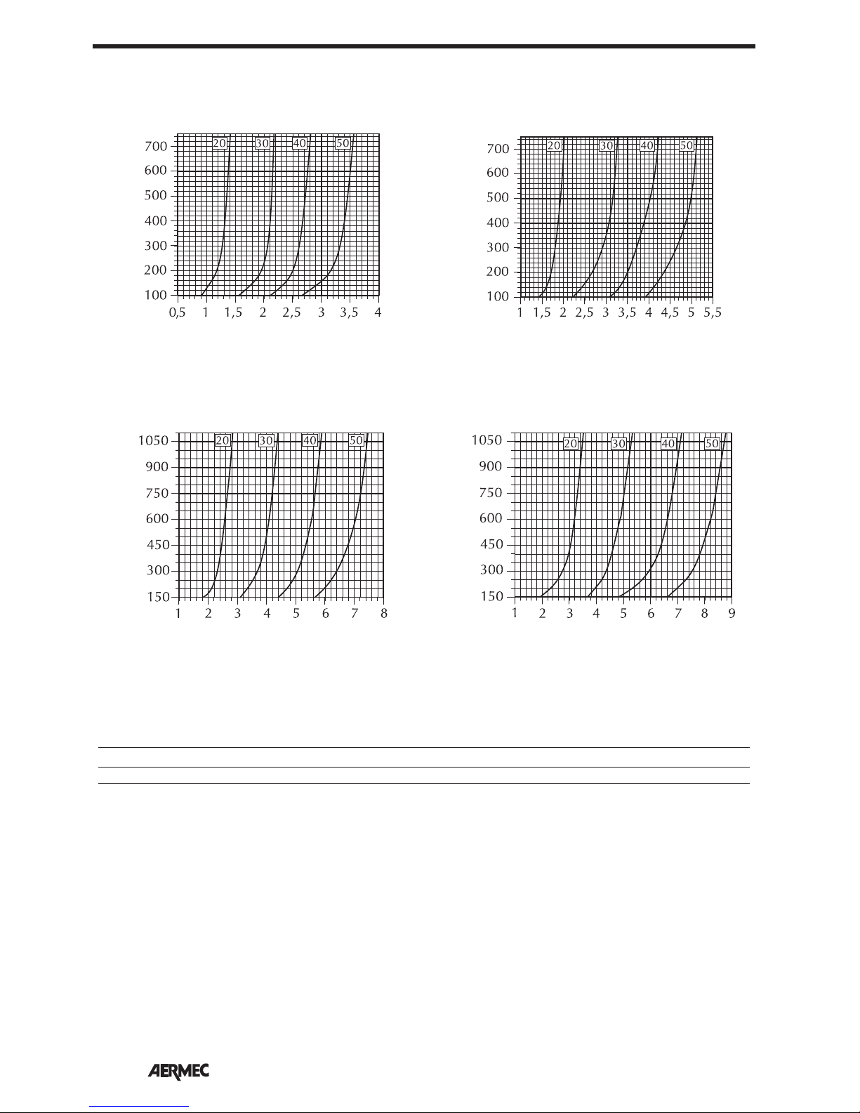
Water flow rate [l/h]
Δt °C (water inlet temperature - air inlet temperature)
Heating capacity [kW]
VEC 20
HEATING CAPACITY YIELDED WITH A 3-ROW COIL
Δt °C (water inlet temperature - air inlet temperature)
Heating capacity [kW]
VEC 30
Water flow rate [l/h]
Δt °C (water inlet temperature - air inlet temperature)
Heating capacity [kW]
VEC 40
Δt °C (water inlet temperature - air inlet temperature)
Heating capacity [kW]
VEC 50
Water flow rate [l/h]Water flow rate [l/h]
HEATING CAPACITY CORRECTION FACTORS
The heat yields refer to the maximum speed. For the rest of the speeds the values must be multiplied by the following factors:
MOD. VEC20 VEC30 VEC40 VEC50
Average speed 0,82 0,85 0,83 0,88
Minimum speed 0,60 0,70 0,67 0,66
Page 17
17
English
Water flow rate [l/h]
Δt °C (water inlet temperature - air inlet temperature)
Heating capacity [kW]
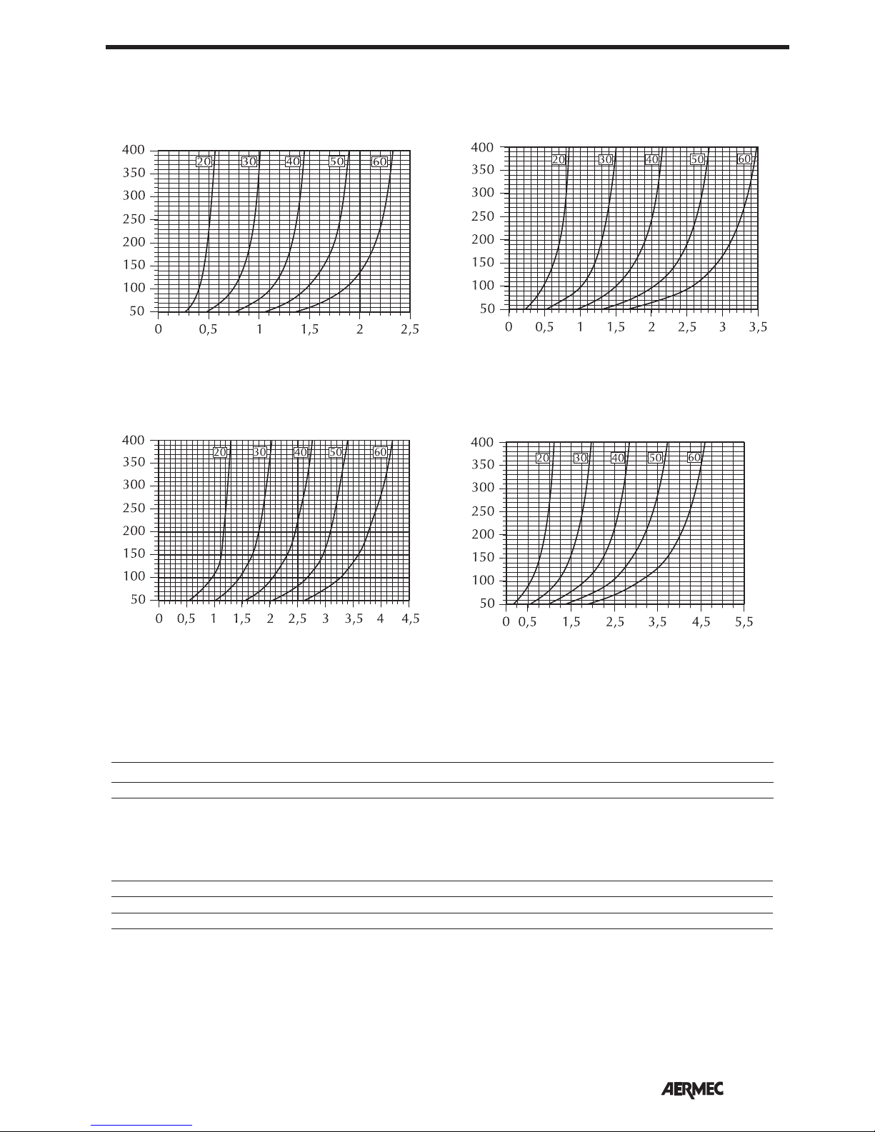
VEC 20 (BV122)
HEATING CAPACITY YIELD FROM 1-ROW COIL (ACCESSORY BV)
Water flow rate [l/h]
Δt °C (water inlet temperature - air inlet temperature)
Heating capacity [kW]
VEC 30 (BV132)
Water flow rate [l/h]
Δt °C (water inlet temperature - air inlet temperature)
Heating capacity [kW]
VEC 40 (BV142)
Water flow rate [l/h]
Δt °C (water inlet temperature - air inlet temperature)
Heating capacity [kW]
VEC 50 (BV142)
HEATING CAPACITY CORRECTION FACTORS
The heat yields refer to the maximum speed. For the rest of the speeds the values must be multiplied by the following factors:
MOD. VEC20 VEC30 VEC40 VEC50
Average speed 0,86 0,87 0,90 0,93
Minimum speed 0,69 0,76 0,81 0,80
The heat yield of the 3-row coil in fan coils fitted with the BV coil accessory (configuration 3R+1R) is indicated in the diagrams
relating to the 3-row standard coils, applying the coefficients shown below.
Total cooling capacity = 0,99
Total perceived cooling capacity = 0,98
Heating = 0,99
Page 18
18
English
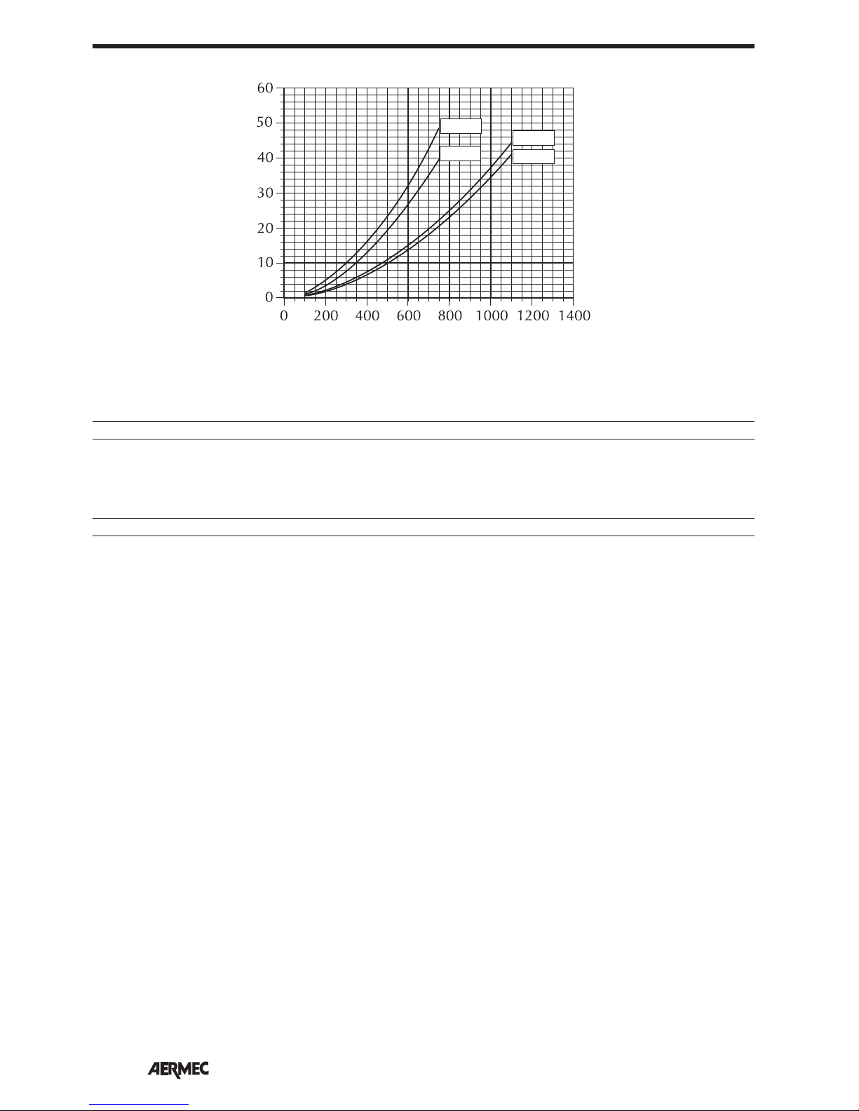
VEC20
VEC30
VEC40
VEC50
Water flow rate [l/h]
Coil pressure drops [kPa]
3R COIL PRESSURE DROPS
The pressure drops in the previous diagram refer to an average water temperature of 10°C. The following table shows the correction to apply to the pressure drop when the average water temperature varies.
Average water temperature °C 5 10 15 20 50 60 70
Multiplication coefficient 1.03 1 0.96 0.91 0.78 0.75 0.72
The pressure drops in the previous diagram refer to an average water temperature of 65°C. The following table shows the correction to apply to the pressure drop when the average water temperature varies.
Average water temperature °C 5 10 15 20 50 60 70
Multiplication coefficient 1.4 1.36 1.31 1.24 1.06 1.02 0.98
Page 19
19
English
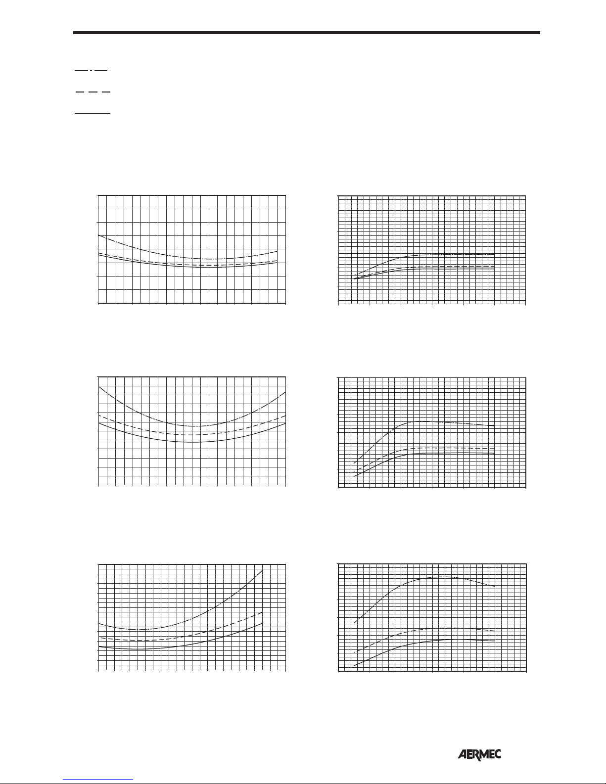
Average glycol water temperature
Correction factor
Pressure drop
Air flow rate
Yield
GLYCOL WATER AT 10%
CORRECTION FACTORS WHEN OPERATING USING GLYCOL WATER
COOLING FUNCTION MODE HEATING FUNCTION MODE
Key:
0,8
0,9
1,0
1,1
1,2
6 7 8 9 10 11 12 13 14 15 16 17 °C
GLYCOL WATER AT 35%
GLYCOL WATER AT 20%
0,6
0,7
0,8
0,9
1,0
1,1
1,2
6 7 8 9 10 11 12 13 14 15 16 17 °C
Average glycol water temperature
Correction factor
0,5
0,6
0,7
0,8
0,9
1,0
1,1
1,2
1,3
1,4
1,5
1,6
6 7 8 9 10 11 12 13 14 15 16 17 18 °C
Average glycol water temperature
Correction factor
30 40 50 60 70 80 90 °C
0,8
0,9
1,0
1,1
1,2
1,3
1,4
Average glycol water temperature
Correction factor
0,8
0,9
1,0
1,1
1,2
1,3
1,4
30 40 50 60 70 80 90 °C
Average glycol water temperature
Correction factor
0,8
0,9
1,0
1,1
1,2
1,3
1,4
30 40 50 60 70 80 90 °C
Average glycol water temperature
Correction factor
Page 20
20
English
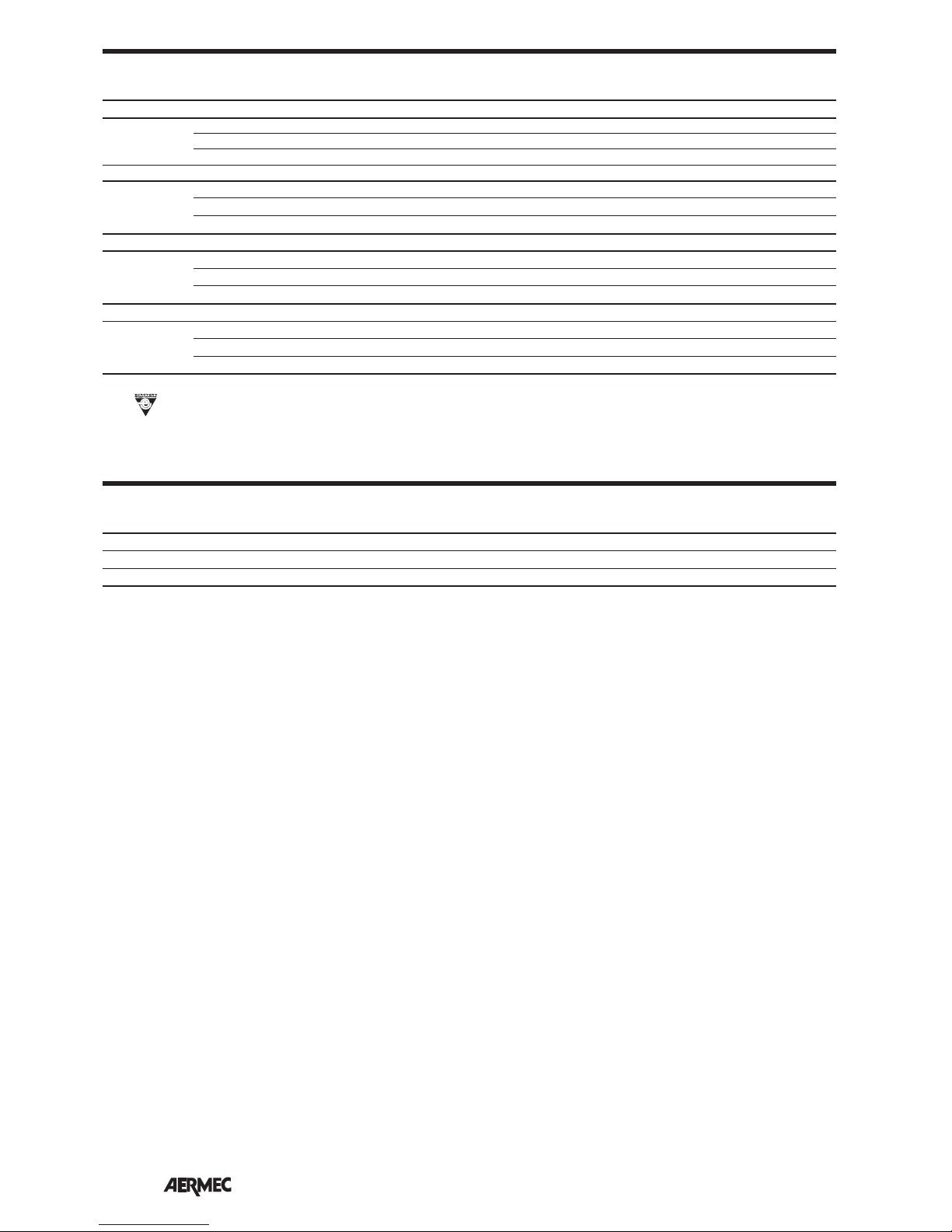
Level of sound pressure (A-weighted) measured in the room with volume V = 85 m3; reverberation time t = 0.5 s; direction factor
Q = 2; distance r = 2.5 m.
(E) =
Eurovent certified performances.
SOUND PRESSURE LEVEL expressed in dB (A)
SOUND POWER LEVEL expressed in dB
Speed Central band frequency [Hz] Overall
M
od. 125 250 500 1000 2000 4000 8000 dB dB(A)
Max 43.3 48.6 46.4 42.7 39.3 31.3 17.7 52.2 48 (E)
VEC20 Med 38.2 43.9 40.8 36.4 31 24.9 6.5 49.9 42 (E)
Min 29.8 37 33.1 30.2 23.9 20.2 6.6 39.7 35 (E)
Max 40.6 45.8 43.4 39.7 36 28.3 14.7 49.3 45 (E)
VEC30 Med 36 42 38.7 34.7 28.9 23 4.4 44.9 40 (E)
Min 29.9 37.1 33.2 30 23.9 20.2 4.1 39.8 35 (E)
Max 44.1 49.3 46.9 43.2 39.5 31.8 18.2 52.8 48.5 (E)
VEC40 Med 38.6 43.8 41.4 37.7 34 26.3 12.7 47.3 43 (E)
Min 32.9 40.1 36.2 33 26.9 23.2 7.1 42.8 38 (E)
Max 48.6 53.8 51.4 47.7 44 36.3 22.7 57.3 53 (E)
VEC50 Med 45.6 50.8 48.4 44.7 41 33.3 19.7 54.3 50
(E)
Min 38.6
43.8 41.4 37.7 34 26.3 12.7 47.3 43 (E)
Velocità Mod. VEC 20 30 40 50
Max 39,5 36,5 40,0 44,5
Med 33,5 31,5 34,5 41,5
Min 26,5 26,5 29,5 34,5
Page 21

21
English
OBLIGATORY ACCESSORIES:
essential for unit operation:
VEC_GL
Air suction and delivery grille with
Coanda effect adjustable outlets.
White RAL 9010.
CONTROL PANELS
FMT10 FLUSH-MOUNTING CONTROL
PANEL WITH ELECTRONIC THERMOSTAT
Electronic thermostat for fan coils instal-
led in
systems with 4 pipes, 2 pipes and
2 pipes with heater, with the possibility
to connect two On-Off valves to shut off
the water feeding the coils. Commands
simplified with only two selectors for
temperature and ventilation control (3
speeds). External air sensor (6m cable
supplied with probe-holder) to be
positioned inside the fan coil. Flushmounting (module 503).
See the accessory instructions for further
information.
FMT20AW FLUSH-MOUNTING
CONTROL PANEL WITH ELECTRONIC
THERMOSTAT AND LCD DISPLAY
Electronic thermostat with LCD display
for fan coils installed in systems with
4 pipes, 2 pipes and 2 pipes with
heater, with the possibility to connect
two On-Off valves to shut off the water
feeding the coils. Air temperature sensor
inside the panel. You can connect a
room air temperature sensor (accessory
SWA). You can connect a system water
temperature sensor (accessory SWA).
Flush-mounting (module 503).
KTL P REMOTE CONTROL KIT WITH
THERMOSTAT
Kit with regulating thermostat, consisting
of an infrared remote control, an infrared
receiver, an electronic control card with
air temperature probe, a connection
cable, brackets and everything required
for fixing. KTLP can be applied to a fan
coil installed in a 2-pipe system with
or without a water valve, or a 4-pipe
system with water valves.
See the acces-
sory instructions for further information.
PTI MULTIFUNCTION CONTROL
PA
NEL WITH THERMOSTAT
Electronic control panel with multifunction electronic thermostat for wallmounted 2-pipe systems.See the accessory instructions for further information.
PX2 CONTROL PANEL WITH SELECTOR
Control panel with manual command
of the ventilation speed, consisting of
on/off selector and a 3-position selector
for fan speed. Wall mounting. See the
accessory instructions for further information.
PXA E CONTROL PANEL WITH MULTIFUNCTION ELECTRONIC THERMOSTAT
Multifunction, electronic room thermostat for fan coils in 2-pipe or 4-pipe
systems. Simplified controls with only
two selectors to control temperature and
ventilation, 3 speeds + automatic speed,
on-off and automatic summer-winter
switching, according to water tempera-
ture. The minimum water temperature
sensor SW is available as an accessory. It
interrupts the heating function when the
water temperature is below 35°C. Wallmounted installation.
See the accessory instructions for further
information.
PXA I CONTROL PANEL WITH MULTIFUNCTION ELECTRONIC THERMOSTAT
Multifunction, electronic room thermostat for fan coils in 2-pipe or 4-pipe
systems. Simplified controls with only
two selectors to control temperature and
ventilation, 3 speeds + automatic speed,
on-off and automatic summer-winter
switching, according to water temperature. Equipped with a minimum water
temperature sensor that interrupts the
heating function when the water temperature is below 35°C. Installation on
machine. See the accessory instructions
for further information.
PXA R CONTROL PANEL WITH MULTIFUNCTION ELECTRONIC THERMOSTAT
Multifunction, electronic room thermostat for fan coils in 2-pipe systems and
an electric heater. Simplified commands with only two selectors to control
temperature and ventilation, 3 speeds +
automatic speed, on/off, activation of the
electric heater when desired, and automatic summer/winter switchover according to water temperature. Equipped
with a minimum water temperature sensor that interrupts the heating function
when the water temperature is below
35°C. By suitably adjusting the dip
switches on the card, it can also be used
for 2-pipe or 4-pipe systems without an
electric heater. Wall mounting. See the
accessory instructions for further information.
WMT05 CONTROL PANEL WITH
THERMOSTAT
Electronic thermostat for fan coils in
2-pipe systems. The panel is electrically protected by an internal fuse. Wallmounted installation. See the accessory
instructions for further information.
WMT10 CONTROL PANEL WITH
THERMOSTAT
Electromechanical thermostat for fan
coils installed in 4-pipe, 2-pipe and
2-pipe with heater systems, with the possibility of connecting two On-Off valves
to shut off the water feeding the coils.
The panel is electrically pro
tected by an
internal fuse. Continuous or thermostatcontrolled ventilation. Wall mounting.
ACCESSORIES:
AMP SUPPORTS FOR HANGING
INSTALLATIONS
The installation kit includes the brackets
and nuts and bolts for fixing to the ceiling.
BC AUXILIARY TRAY FOR
COLLECTING CONDENSATE
Made of thermoplastic material, it collects and channels outwards the condensate that is formed during the summer
functioning mode, near the non-insulated plumbing connections.
BV WATER-BASED HEATING COIL
The 1-row heating coil that works with
hot water can be installed in fan coils
in 4-pipe systems, positioned above the
standard coil. The coil can be adjusted
via a control panel able to command the
double valve.
DSC CONDENSATE DISCHARGE DEVICE
Thanks to a pump, this allows you to
discharge the condensate when there
is a difference of levels. It is assembled
outside the device.
PCR COMMAND PROTECTION
In galvanised sheet iron, this is used to
protect the commands and the electric
control board in hanging version models
with electric heater.
RX ELECTRIC HEATER
Protected electric heater complete with
safety thermostat. Available as an accessory for all versions.
SIT 3
Each fan coil fitted with a SIT3 card
becomes a Slave and can be controlled
from a centralised control panel with
an electromechanical selector or with
SIT5. Up to ten fan coils fitted with SIT
3 can be applied to a single centralised
command.The electronic control panels
and those with valve control must also
be interfaced with a SIT 5. The electro-
mechanical control panel with just the
speed control can be fitted directly to
the SIT 3 without the SIT 5 interface.
SIT 5
The SIT 5 accessory, a Master interface
card, connects to the electronic control panels or electromechanical control
panels with command of the valves and/
or electric heaters. The SIT5 interface
card requires that all fan coils connected
to it (up to 10) be fitted with SIT3 Slave
interface cards.
SW3 MINIMUM WATER TEMPERATURE SENSOR
The SW3 accessory is a sensor that
detects the temperature of the water inside the heating coil and it prevent the
fans from working when the water temperature is less than 39°C. The SW3 sensors are fit for 230V single phase power
supply. The sensor has a 2500mm long
cable.
SWA TEMPERATURE PROBE
SWA outside probe accessory (length L =
6m). The probe detects the temperature
of the ambient air if connected to the
connector (A) of the panel FMT20AW;
the ambient air temperature probe incorporated in the panel is automatically
deactivated. It detects the temperature
of the water in the system, for ventilation
consent, if connected to the connector
(W) of the panel FMT20AW. Two SWA
probes can be connected to the panel
FMT20AW simultaneously.
ACCESSORIES
Page 22
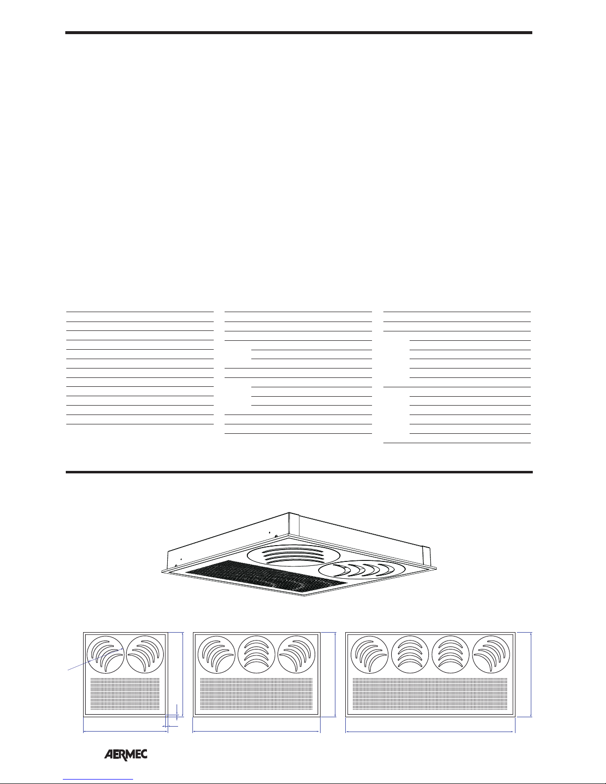
22
English
VCF 3-WAY VALVES KIT
The SW3 sensor should be used with
this accessory.
Kits complete with copper pipe fittings and 3-way valves of the "all
or nothing" type that work with a
230V and 24V power supply.
Available for fan coils:
- with a 3-row coil (VCF41, VCF4124,
VCF42, VCF4224)
- with additional 1-row coil (BV)
(VCF44, VCF4424).
VCFD 2-WAY VALVES KIT
The SW3 sensor should be used with
this accessory.
Kits complete with copper pipe fittings and 3-way valves of the "all
or nothing" type that work with a
230V and 24V power supply.
Available for fan coils:
- with 3-row coil (VCFD1, VCFD124,
VCFD2, VCFD224)
- with additional 1-row coil (BV)
(VCFD4, VCFD5).
ACCESSORIES
Consult the compatibility table to make your choice.
Obligatory VEC
accessory 20 30 40 50
VEC20GL
✔
VEC30GL ✔
VEC40GL ✔ ✔
FMT10 ✔ ✔ ✔ ✔
FMT20AW ✔ ✔ ✔ ✔
KTLP ✔ ✔ ✔ ✔
PX2 ✔ ✔ ✔ ✔
PXAE ✔ ✔ ✔ ✔
PXAR ✔ ✔ ✔ ✔
WMT05 ✔ ✔ ✔ ✔
WMT10 ✔ ✔ ✔ ✔
VEC
Accessory 20 30 40 50
AMP
✔ ✔ ✔ ✔
AMP 20 ✔ ✔ ✔ ✔
BC 5 ✔ ✔ ✔ ✔
122 ✔
BV 132
✔
142
✔ ✔
DSC 4 ✔ ✔ ✔ ✔
22 ✔
RX
32
✔
42
✔
52
✔
SIT3 ✔ ✔ ✔ ✔
SIT5 ✔ ✔ ✔ ✔
VEC
Accessory 20 30 40 50
SW3
✔ ✔ ✔ ✔
SWA ✔ ✔ ✔ ✔
41 ✔ ✔
42
✔ ✔
VCF
44*
✔ ✔ ✔ ✔
4124 ✔ ✔
4224
✔ ✔
4424* ✔ ✔ ✔ ✔
1 ✔ ✔
2
✔ ✔
VCFD
4*
✔ ✔ ✔ ✔
124 ✔ ✔
224
✔ ✔
424* ✔ ✔ ✔ ✔
595
1195
895
595
Ø262
595
15
15
595
VEC20GL VEC40GLVEC30GL
VEC20GL
OBLIGATORY ACCESSORIES
Page 23
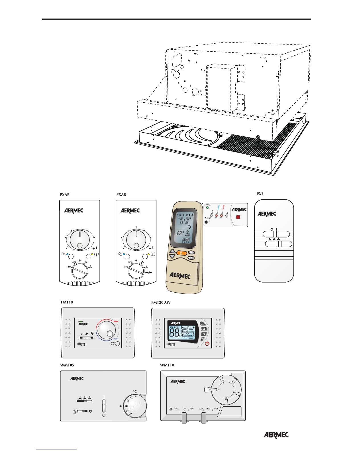
23
English
OBLIGATORY ACCESSORIES
KTLP
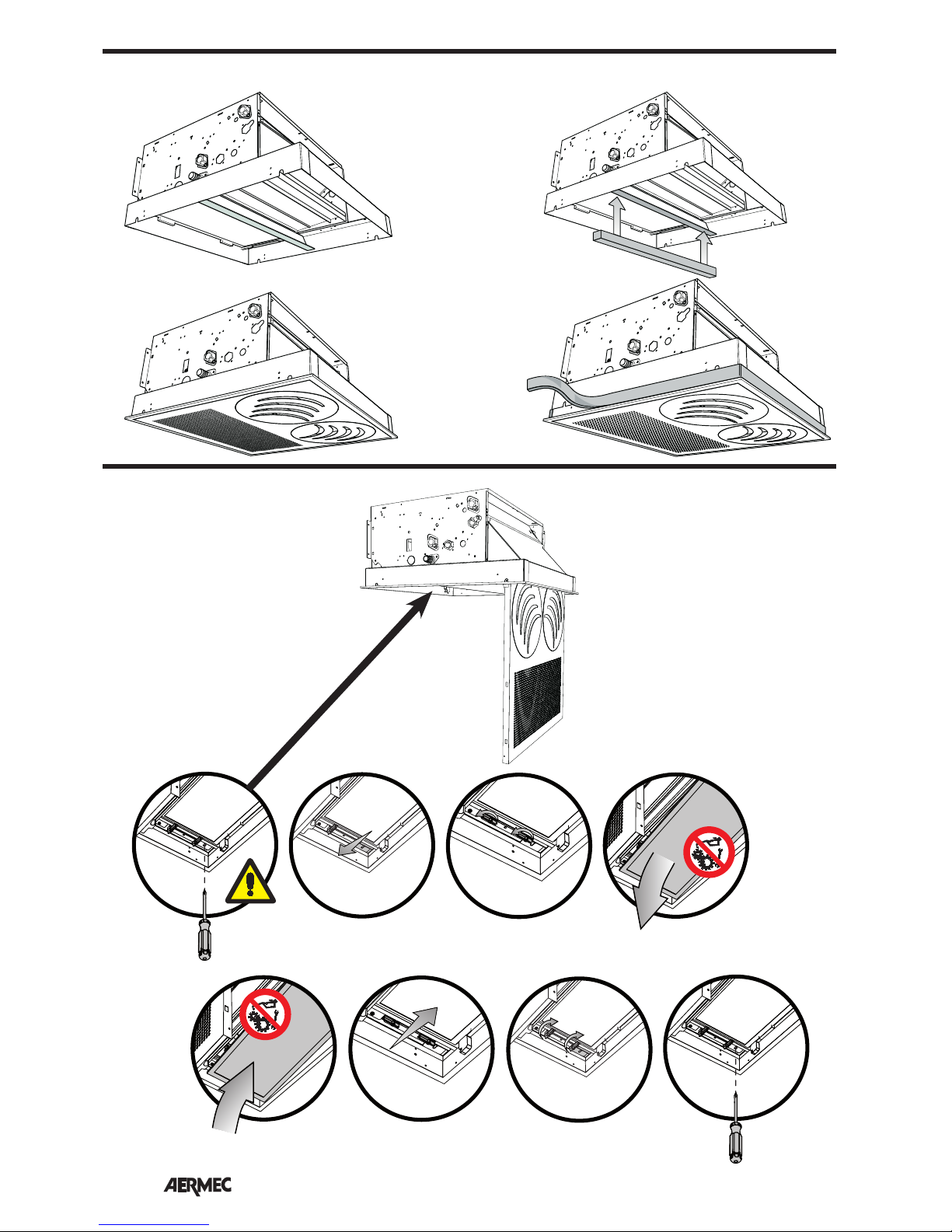
VEC_GL allows 2 installation positions:
A) for suspended ceiling installation
with reduced space that requires units
with small dimensions.
B) allows (increasing total height)
to increase the difference in level
between condensate drain and
suspended ceiling by a further 30
mm, to make the realisation of the
condensate drain ducting even easier,
in order to prevent, in most cases,
the necessity for a condensate drain
pump. In this case it is mandatory to
apply the insulating gasket to the filter
retainer divider (supplied) to prevent
by-pass between intake and flow.
Moreover, after having fixed the frame
to the fan coil using the 4 screws,
apply the insulating tape (supplied)
to the entire exposed perimeter of the
frame.
WARNING: No or incorrect
installation of the insulating products
caused the reduction in performance
and the formation of condensate on
the surfaces.
Page 24
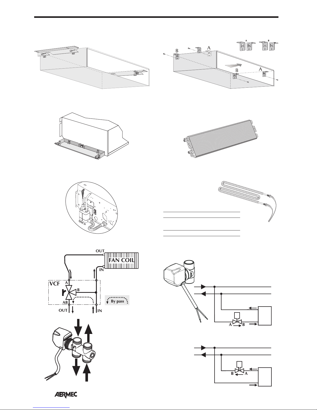
24
English
FanCoil
VCFD4
FanCoil
VCFD1-2-3
ACCESSORIES
BC5 CONDENSATE COLLECTION TRAY
AMP SUPPORTS FOR INSTALLATION
Heating capacity of electric heater [W]
RX 22 RX 32 RX 42 RX 50
950 1300 1650 1950
Electric heater input current [A]
RX 22 RX 32 RX 42 RX 50
4,13 5,65 7,17 8,48
AMP20 SUPPORTS FOR INSTALLATION
BV WATER-BASED HEATING COIL
DSC4 CONDENSATE DISCHARGE DEVICE RX ELECTRIC HEATER
VCFD 2-WAY VALVE
Flow direction
VCF 3-WAY VALVE
A
B
AB
IN
OUT
Page 25
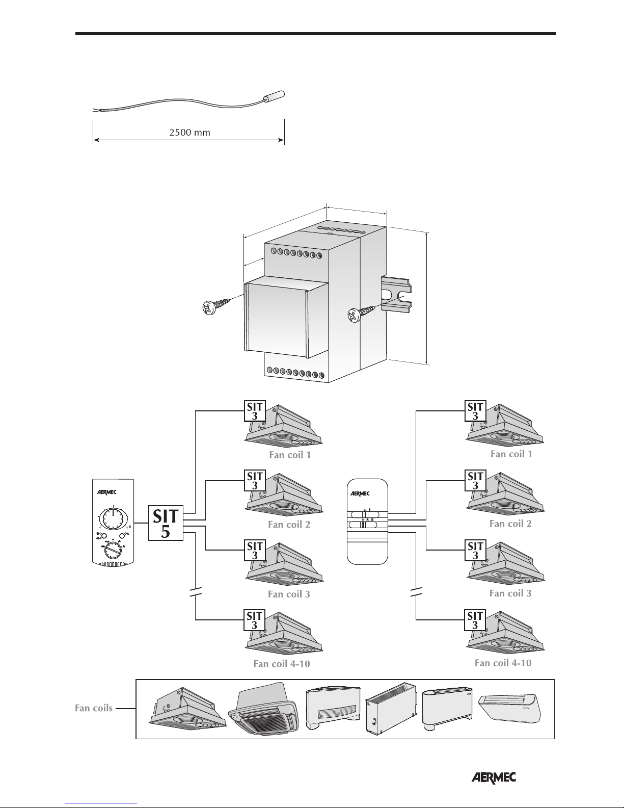
25
English
SIT3 - SIT5 INTERFACE CARDS
V1
V2
V3
OUTPUT
N
PH
L
V2
V1
N
V3
INPUT
52
65
90
15
DIN
SIT 3
SIT 5
ACCESSORIES
SW3 MINIMUM WATER TEMPERATURE SENSOR
Page 26
26
English
The unit must be connected directly
to an electrical outlet or to an
independent circuit.
To protect the unit against short circuits, fit an omnipolar thermal-magnetic
trip 2A 250V (IG) to the power line
with a minimum contact opening
distance of 3mm.
CHARACTERISTICS OF THE
CONNECTION CABLES
Use H05V-K or N07V-K type cables
with 300/500V with insulation, piped
or ducted.
All the cables must be piped or ducted
until they are inside the fan coil.
The cables coming out of the pipe or
duct must not be subject to stretching
or twisting. They must be protected from
external agents.
Stranded wires can only be used with
terminating sleeves. Make sure that the
strands of the wires are inserted properly.
Wiring diagrams are constantly updated. It is therefore compulsory to refer
to the ones supplied with the unit.
The control panel may not be fitted on
a metal wall unless this is permanently
connected to an earthed outlet.
The control panels consist simply of
electric circuits connected at the mains
voltage of 230V; all the inputs for the
probes and controls must therefore be
correspondingly insulated for this voltage.
Multifunctional electronic thermostats
are provided ready for operation in the
standard configuration but allow the
installer to adjust them to the specific
necessities of the system by modifying
the internal dip-switch configuration.
The functions that can be customised might
vary from model to model, for this reason it
is advisable to consult the relevant manuals.
WARNING:check whether the installation has been carried out correctly. FOLLOW THE CHECKING PROCEDURES indicated in the control panel
manuals.
INSTALLATION
INSTALLING THE UNIT
ELECTRICAL WIRINGS
WARNING: before carrying out any
intervention, check the power supply i
s
disconnected.
WARNING:before carrying out any
work, put the proper individual
protection equipment on.
WARNING: the appliance must be fitted
according to the national regulations on
process plant engineering.
WARNING: electrical wirings,
installation of the fan coils and relevant
accessories should be performed by
a technician who has the necessary
technical and professional expertise
to install, modify, extend and maintain
systems, and who is able to check the
systems for the purposes of safety and
correct operation.
WARNING: install a device, main
switch or plug which allows to
completely cut off the power supply
from the unit.
Instructions which are essential for the
proper installation of the equipment are
given here.
The completion of all the operations
in accordance with the specific
requirements is however left to the
experience of the installation engineer.
Do not install units in rooms where
there are inflammable gases or acid
or alkaline substances that could
irretrievably damage the aluminiumcopper heat exchanger or the internal
plastic parts.
Do not install the unit in workshops or
kitchens where the oil vapours mixed
with the treated air can be deposited
on the exchange coils, reducing their
performance, or on the parts inside the
unit, damaging the plastic parts.
Choose a position at the centre of the
room whenever possible; adjusting the
air output allows air to be distributed
optimally within the room. Do not
install at a height above three metres.
- Choose the place where to install
the unit according to the layout of
the room, the number of units to be
installed and any limitations imposed
by the architecture. Check that the
ch
osen place facilitates installing and
servicing the unit.
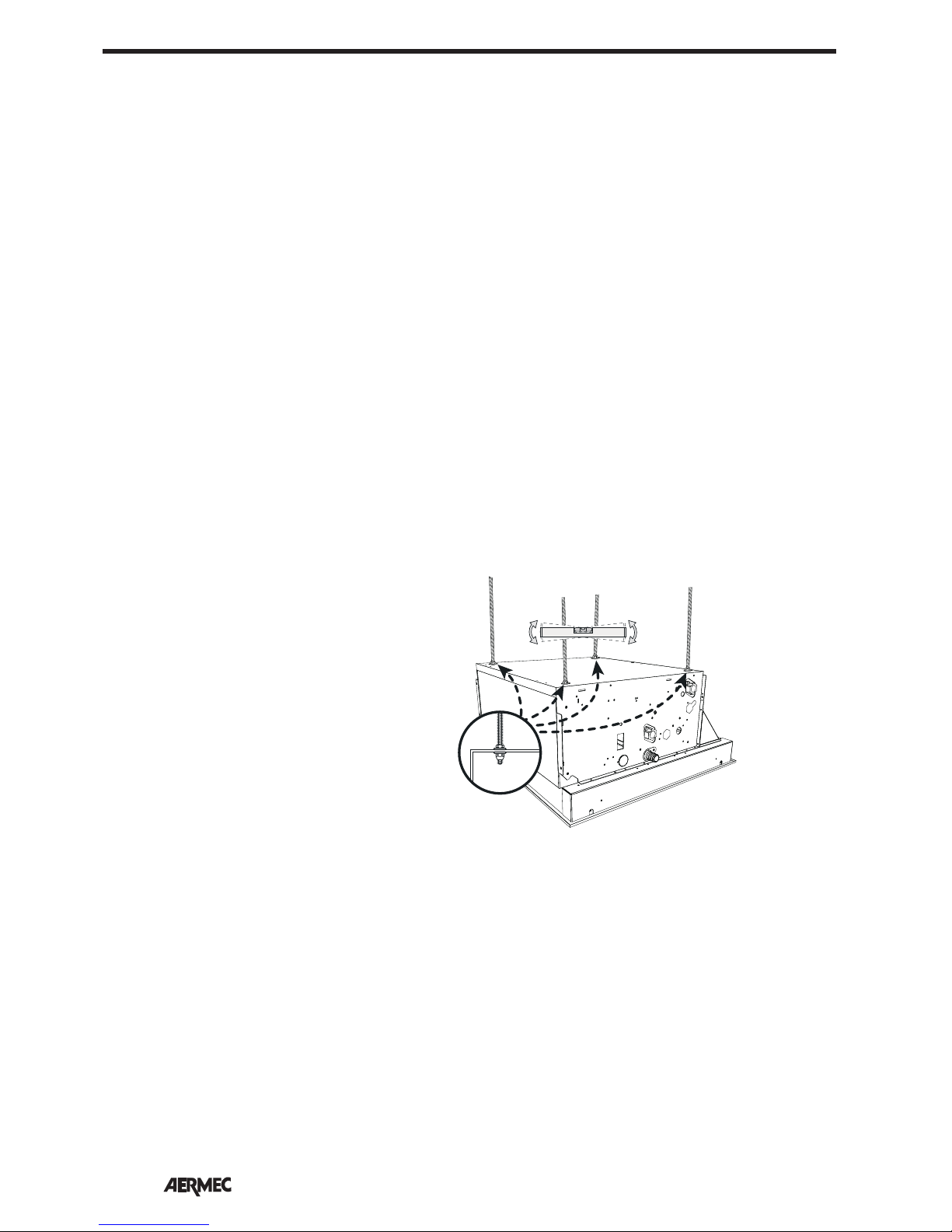
- Install four M8 threaded rods into the
ceiling to hold the frame.
VEC allows 2 installation options thanks
to the grill prepared to be fixed in two
positions:
A) for suspended ceiling installation with
reduced space that requires units with
small dimensions.
B) allows (increasing total height)
to increase the difference in level
between condensate drain and
suspended ceiling by a further 30
mm, to make the realisation of the
condensate drain ducting even easier,
in order to prevent, in most cases,
the necessity for a condensate drain
pump.
To install the VEC unit, proceed as
follows:
- open the cardboard box
- if necessary, mount any accessory
before installing the unit on the ceiling
WARNING: consult the relevant
manuals of the accessories
- lift the unit carefully a
nd, keeping it
slightly inclined, attach it to the 4
threaded bars using 8 nuts, 4 of which
are self-locking. Operate the nuts
to adjust height; finally, check that
the unit is installed in a horizontal
position
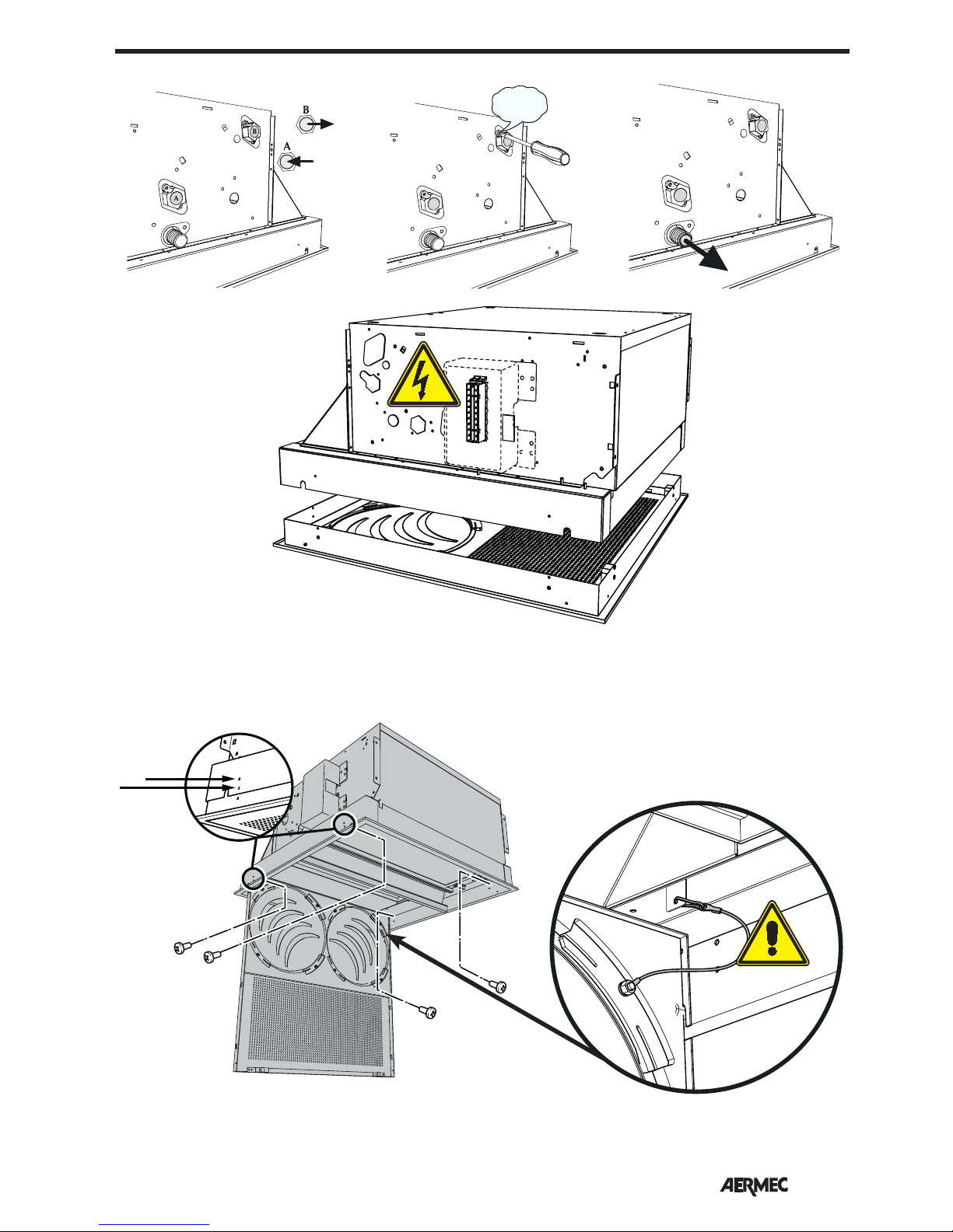
- lay the hydraulic pipes through the
suspended ceiling to the attachment
plate on the unit
- make the hydraulic connections as
described in the relative chapter
- bring the condensate discharge pipe
so that it matches the relative fitting on
the condensate discharge device
- drain the system via the drain valve
- bring the power supply and the
control cables close to the electrical
box
- adjust the position of the unit from the
support bracket by means of the nuts
so that the unit is level and the frame
rests slightly on the suspended ceiling
- start the fan coil unit and carry out
an operation test; the functions are
described in the User Manual
Page 27
27
English
INSTALLATION
H2O
H
2
O
AIR
H
2
O
A
B
Page 28
28
English
INSTALLING AND REPLACING THE AIR FILTER
INSTALLATION
Installation "A" Installation "B"
Page 29
29
English
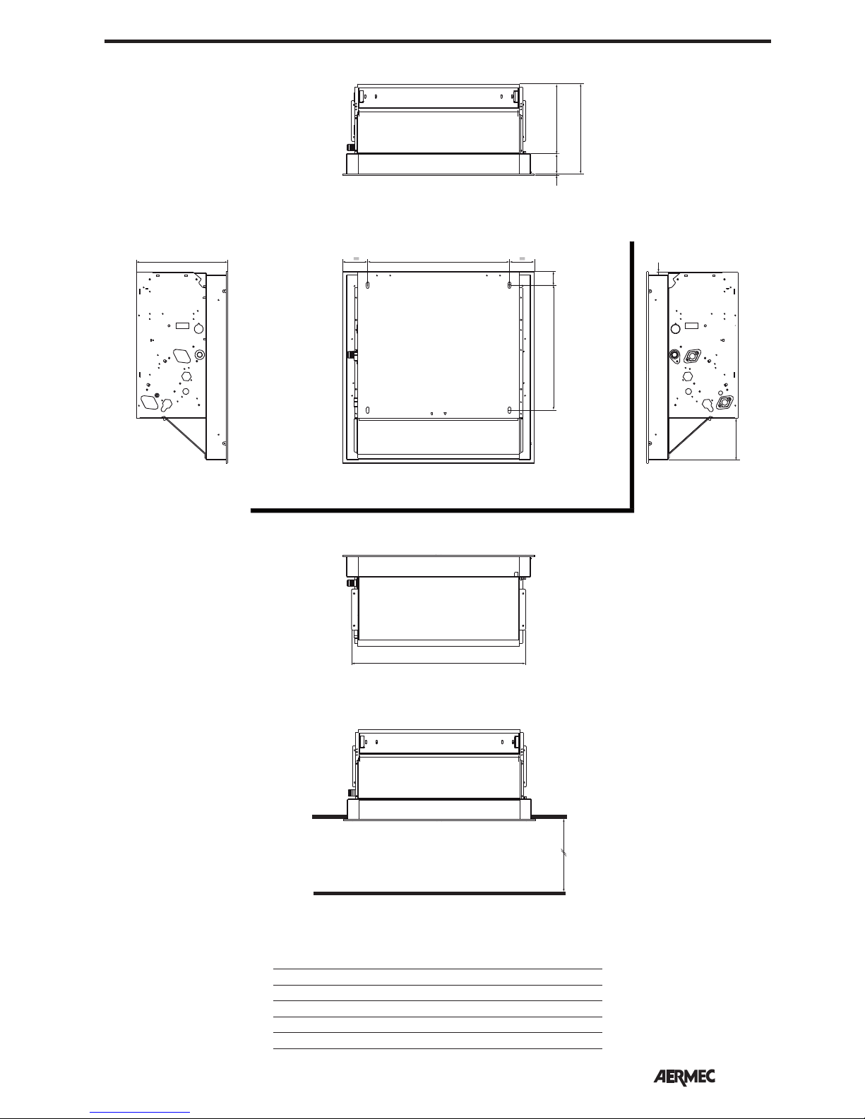
DIMENSIONS [mm]
L
I
Max. 3000mm
284(A) / 314(B)
388
43
129
8
216(A) / 246(B)
279(A) / 309(B)
63
5
VEC 20 30 40 50
L [mm] 540 771 991 991
I [mm] 440 671 891 891
Weight (VEC) [kg] 15,5 20,6 24,7 24,7
Weight (VEC GL) [kg] 3,7 5,7 7 7
Page 30
30
English
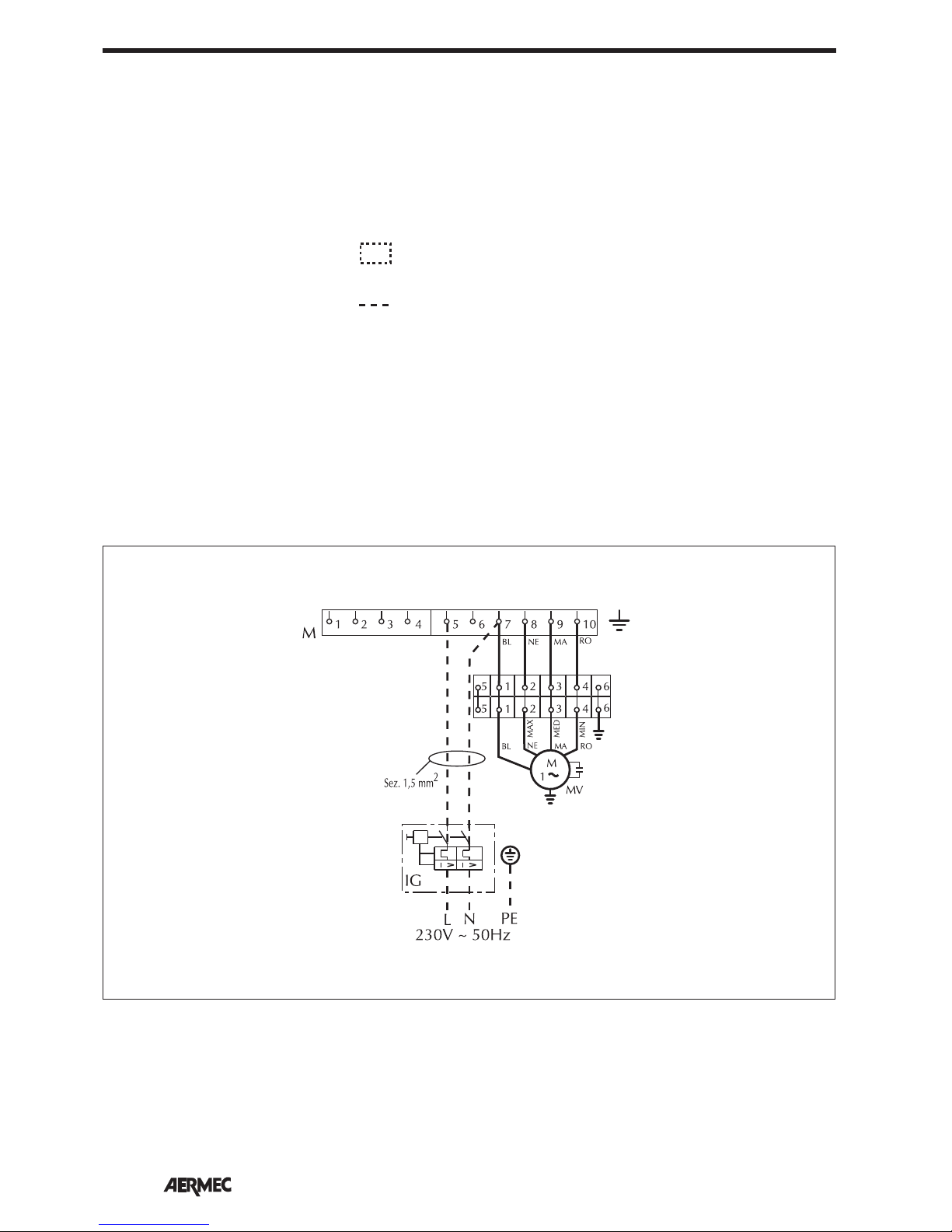
F = Fusibile • Fuse • Fusible
Sicherung • Fusible
IG = Interruttore generale • Main switch
Interupteur général • Hauptschalter
Interruptor general
M = Morsettiera • Terminal board
Boitier • Klemmleiste
Placa de bornes
MV = Motore ventilatore • Fan motor
Moteur ventilateur • Ventilatormotor
Motor del ventilador
PE = Collegamento a terra
Earth connection
Mise à terre
Erdanschluss
Toma de tierra
Sonda temperatura mínima del agua
VCF =Valvola solenoide • Solenoid valve
Vanne solenoide • Magnetventil
Válvula solenoide
SPC = Dispositivo scarico condensa
Condensate drainage device
Dispositif pour évacuation condensation
Kondensatablauf Einrichtung
Dispositivo para desagüe de condensación
= Componenti non forniti
Components not supplied
Composants non fournis
Nicht lieferbare Teile
Componentes no suministrados
= Componenti forniti optional
Optional components
Composants en option
Optionsteile
Componentes opcionales
= Collegamenti da eseguire in loco
On-site wiring
Raccordements à effectuer in situ
Vor Ort auszuführende Anschlüsse
Cableado in situ
AR = Arancio • Orange • Orange • Orange • Naranja
BI = Bianco • White • Blanc • Weiss • Blanco
BL = Blu • Blue • Bleu • Blau • Azul
GR = Grigio • Grey • Gris • Gray • Gris
MA = Marrone • Brown • Marron • Braun • Marrón
NE = Nero • Black • Noir • Schwarz • Negro
RO = Rosso • Red • Rouge • Rot • Rojo
VE = Verde • Green • Vert • Grün • Verde
VI = Viola • Violet • Violet • Violet • Violeta
READING KEY
WIRING DIAGRAMS
Gli schemi elettrici sono soggetti ad un continuo aggiornamento, è obbligatorio quindi fare riferimento a quelli a bordo macchina.
All wiring diagrams are constantly updated. Please refer to the ones supplied with the unit.
Nos schémas électriques étant constamment mis à jour, il faut absolument se référer à ceux fournis à bord de nos appareils.
Die Schaltpläne werden ständig aktualisiert, deswegen muss man sich stets auf das mit dem Gerät gelieferte Schaltschema beziehen.
El cableado de las máquinas es sometido a actualizaciones constantes. Por favor, para cada unidad hagan referencia a los esquemas suministrados con la misma.
Page 31
31
English
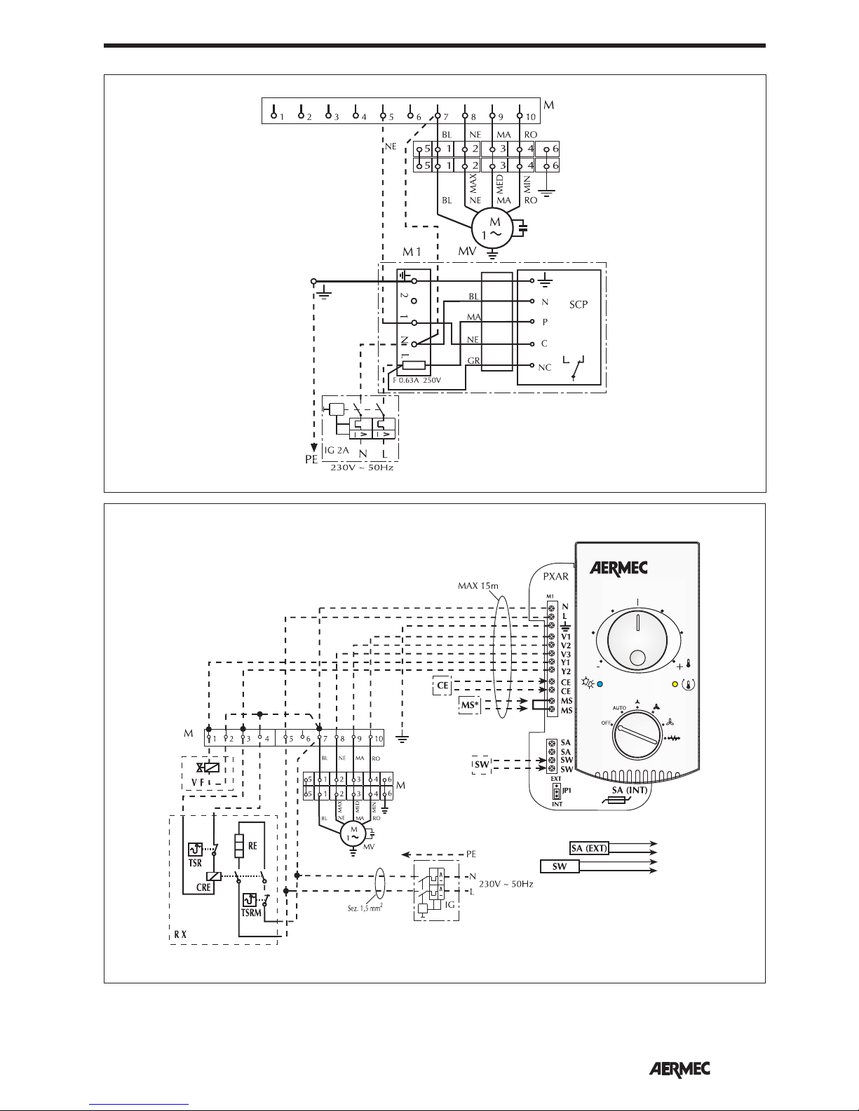
SCHEMI ELETTRICI • WIRING DIAGRAMS • SCHEMAS ELECTRIQUES • SCHALTPLÄNE • ESQUEMAS ELÉCTRICOS
Gli schemi elettrici sono soggetti ad un continuo aggiornamento, è obbligatorio quindi fare riferimento a quelli a bordo macchina.
All wiring diagrams are constantly updated. Please refer to the ones supplied with the unit.
Nos schémas électriques étant constamment mis à jour, il faut absolument se référer à ceux fournis à bord de nos appareils.
Die Schaltpläne werden ständig aktualisiert, deswegen muss man sich stets auf das mit dem Gerät gelieferte Schaltschema beziehen.
El cableado de las máquinas es sometido a actualizaciones constantes. Por favor, para cada unidad hagan referencia a los esquemas suministrados con la misma.
BL
VEC
DSC
VEC
PXAR + VF + RX
2 tubi pannello PXAR a muro
2 tubes PXAR wall-mounted panel
2 tuyaux panneau PXAR inst. murale
2 Röhren Platte PXAR an Wand
2 tubos panel PXAR mural
Page 32
32
English
VEC
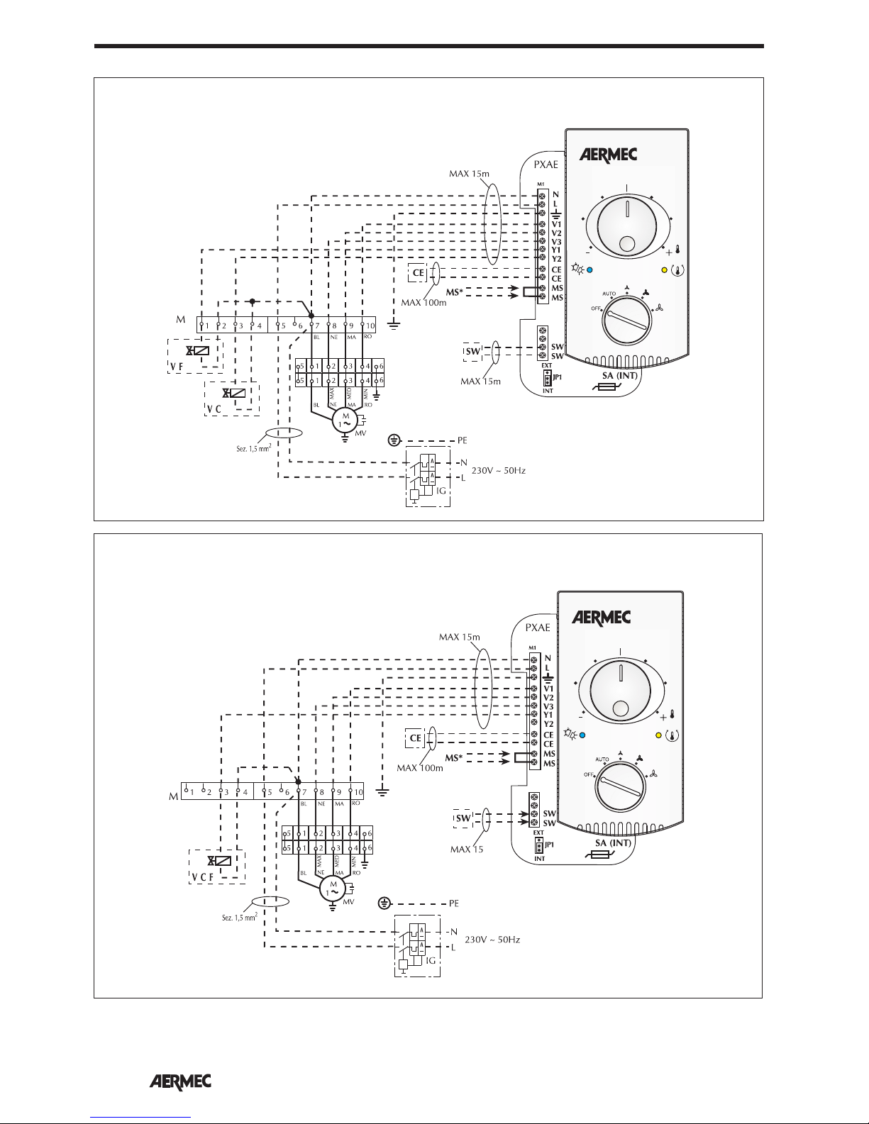
PXAE + VC + VF
VEC
PXAE + VCF
4 tubi pannello PXAE a muro
4 tubes PXAE wall-mounted panel
4 tuyaux panneau PXAE inst. murale
4 Röhren Platte PXAE an Wand
4 tubos panel PXAE mural
2 tubi pannello PXAE a muro
2 tubes PXAE wall-mounted panel
2 tuyaux panneau PXAE inst. murale
2 Röhren Platte PXAE an Wand
2 tubos panel PXAE mural
Gli schemi elettrici sono soggetti ad un continuo aggiornamento, è obbligatorio quindi fare riferimento a quelli a bordo macchina.
All wiring diagrams are constantly updated. Please refer to the ones supplied with the unit.
Nos schémas électriques étant constamment mis à jour, il faut absolument se référer à ceux fournis à bord de nos appareils.
Die Schaltpläne werden ständig aktualisiert, deswegen muss man sich stets auf das mit dem Gerät gelieferte Schaltschema beziehen.
El cableado de las máquinas es sometido a actualizaciones constantes. Por favor, para cada unidad hagan referencia a los esquemas suministrados con la misma.
SCHEMI ELETTRICI • WIRING DIAGRAMS • SCHEMAS ELECTRIQUES • SCHALTPLÄNE • ESQUEMAS ELÉCTRICOS
Page 33
33
English
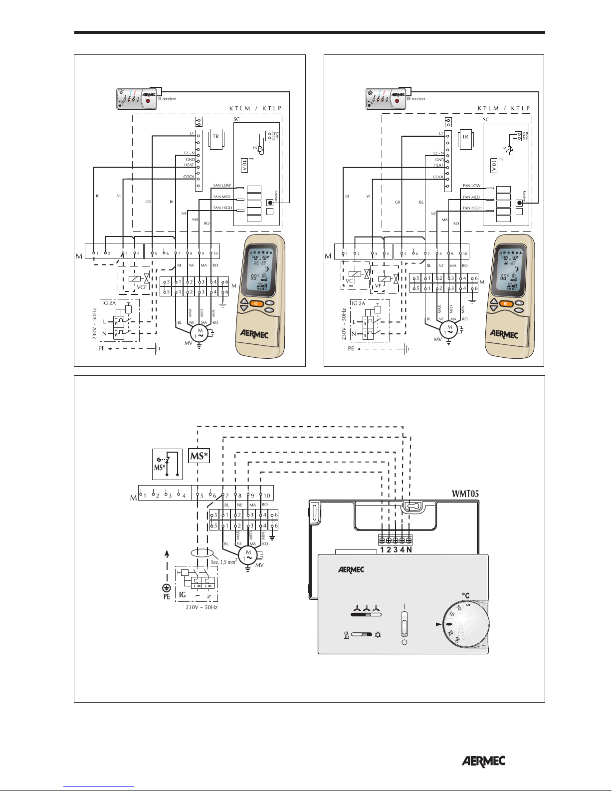
Gli schemi elettrici sono soggetti ad un continuo aggiornamento, è obbligatorio quindi fare riferimento a quelli a bordo macchina.
All wiring diagrams are constantly updated. Please refer to the ones supplied with the unit.
Nos schémas électriques étant constamment mis à jour, il faut absolument se référer à ceux fournis à bord de nos appareils.
Die Schaltpläne werden ständig aktualisiert, deswegen muss man sich stets auf das mit dem Gerät gelieferte Schaltschema beziehen.
El cableado de las máquinas es sometido a actualizaciones constantes. Por favor, para cada unidad hagan referencia a los esquemas suministrados con la misma.
VEC
KTLP + VCF
VEC
KTLP + VC + VF
2 tubi
2 tube
2 tuyaux
2 Röhren
2 tubos
4 tubi
4 tube
4 tuyaux
4 Röhren
4 tubos
VEC
WMT05
2 tubi
2 tube
2 tuyaux
2 Röhren
2 tubos
SCHEMI ELETTRICI • WIRING DIAGRAMS • SCHEMAS ELECTRIQUES • SCHALTPLÄNE • ESQUEMAS ELÉCTRICOS
Page 34
34
English
Gli schemi elettrici sono soggetti ad un continuo aggiornamento, è obbligatorio quindi fare riferimento a quelli a bordo macchina.
All wiring diagrams are constantly updated. Please refer to the ones supplied with the unit.
Nos schémas électriques étant constamment mis à jour, il faut absolument se référer à ceux fournis à bord de nos appareils.
Die Schaltpläne werden ständig aktualisiert, deswegen muss man sich stets auf das mit dem Gerät gelieferte Schaltschema beziehen.
El cableado de las máquinas es sometido a actualizaciones constantes. Por favor, para cada unidad hagan referencia a los esquemas suministrados con la misma.
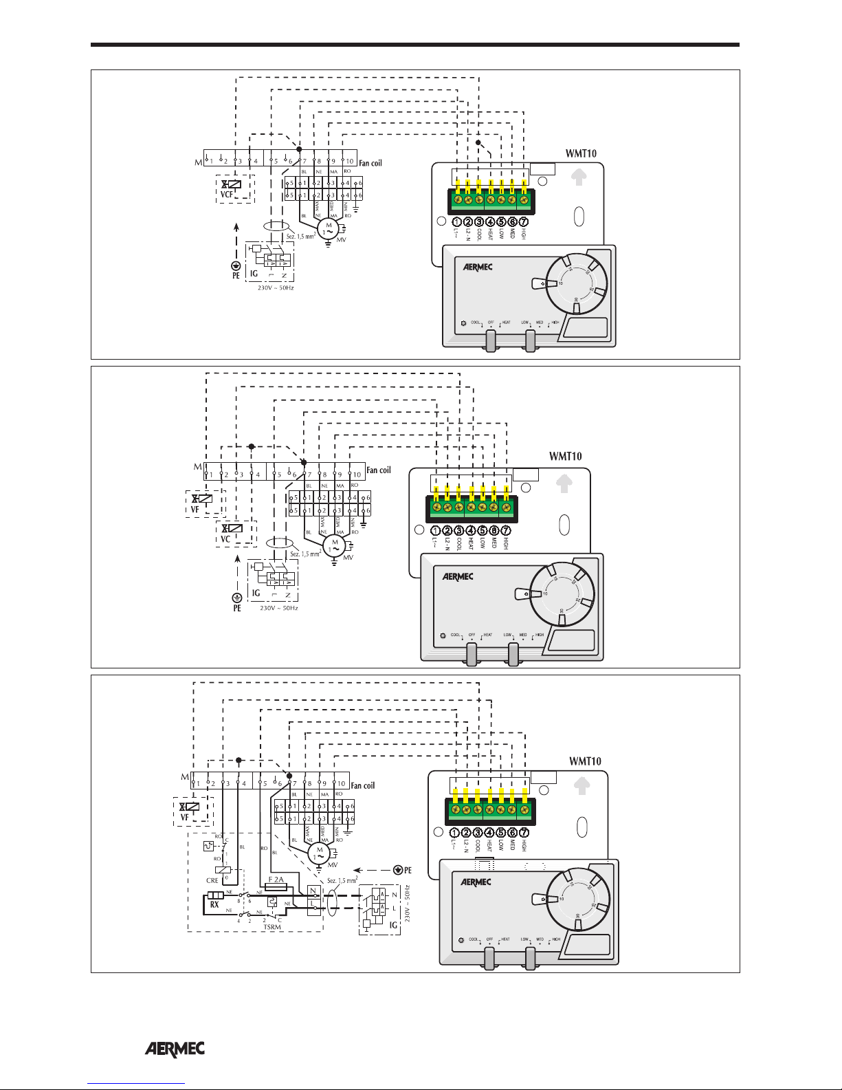
VEC
WMT10 + VCF
2 tubi
2 tube
2 tuyaux
2 Röhren
2 tubos
VEC
WMT10 + VF + VC
4 tubi
4 tube
4 tuyaux
4 Röhren
4 tubos
VEC
WMT10 + VF + RX
2 tubi
2 tube
2 tuyaux
2 Röhren
2 tubos
SCHEMI ELETTRICI • WIRING DIAGRAMS • SCHEMAS ELECTRIQUES • SCHALTPLÄNE • ESQUEMAS ELÉCTRICOS
Page 35
35
English
Gli schemi elettrici sono soggetti ad un continuo aggiornamento, è obbligatorio quindi fare riferimento a quelli a bordo macchina.
All wiring diagrams are constantly updated. Please refer to the ones supplied with the unit.
Nos schémas électriques étant constamment mis à jour, il faut absolument se référer à ceux fournis à bord de nos appareils.
Die Schaltpläne werden ständig aktualisiert, deswegen muss man sich stets auf das mit dem Gerät gelieferte Schaltschema beziehen.
El cableado de las máquinas es sometido a actualizaciones constantes. Por favor, para cada unidad hagan referencia a los esquemas suministrados con la misma.
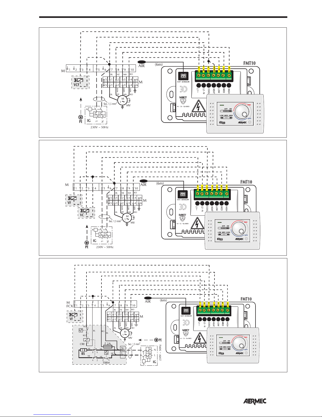
VEC
FMT10 + VCF
2 tubi
2 tube
2 tuyaux
2 Röhren
2 tubos
VEC
FMT10 + VF + VC
4 tubi
4 tube
4 tuyaux
4 Röhren
4 tubos
VEC
FMT10 + VF + RX
2 tubi
2 tube
2 tuyaux
2 Röhren
2 tubos
SCHEMI ELETTRICI • WIRING DIAGRAMS • SCHEMAS ELECTRIQUES • SCHALTPLÄNE • ESQUEMAS ELÉCTRICOS
Page 36
36
English
Gli schemi elettrici sono soggetti ad un continuo aggiornamento, è obbligatorio quindi fare riferimento a quelli a bordo macchina.
All wiring diagrams are constantly updated. Please refer to the ones supplied with the unit.
Nos schémas électriques étant constamment mis à jour, il faut absolument se référer à ceux fournis à bord de nos appareils.
Die Schaltpläne werden ständig aktualisiert, deswegen muss man sich stets auf das mit dem Gerät gelieferte Schaltschema beziehen.
El cableado de las máquinas es sometido a actualizaciones constantes. Por favor, para cada unidad hagan referencia a los esquemas suministrados con la misma.
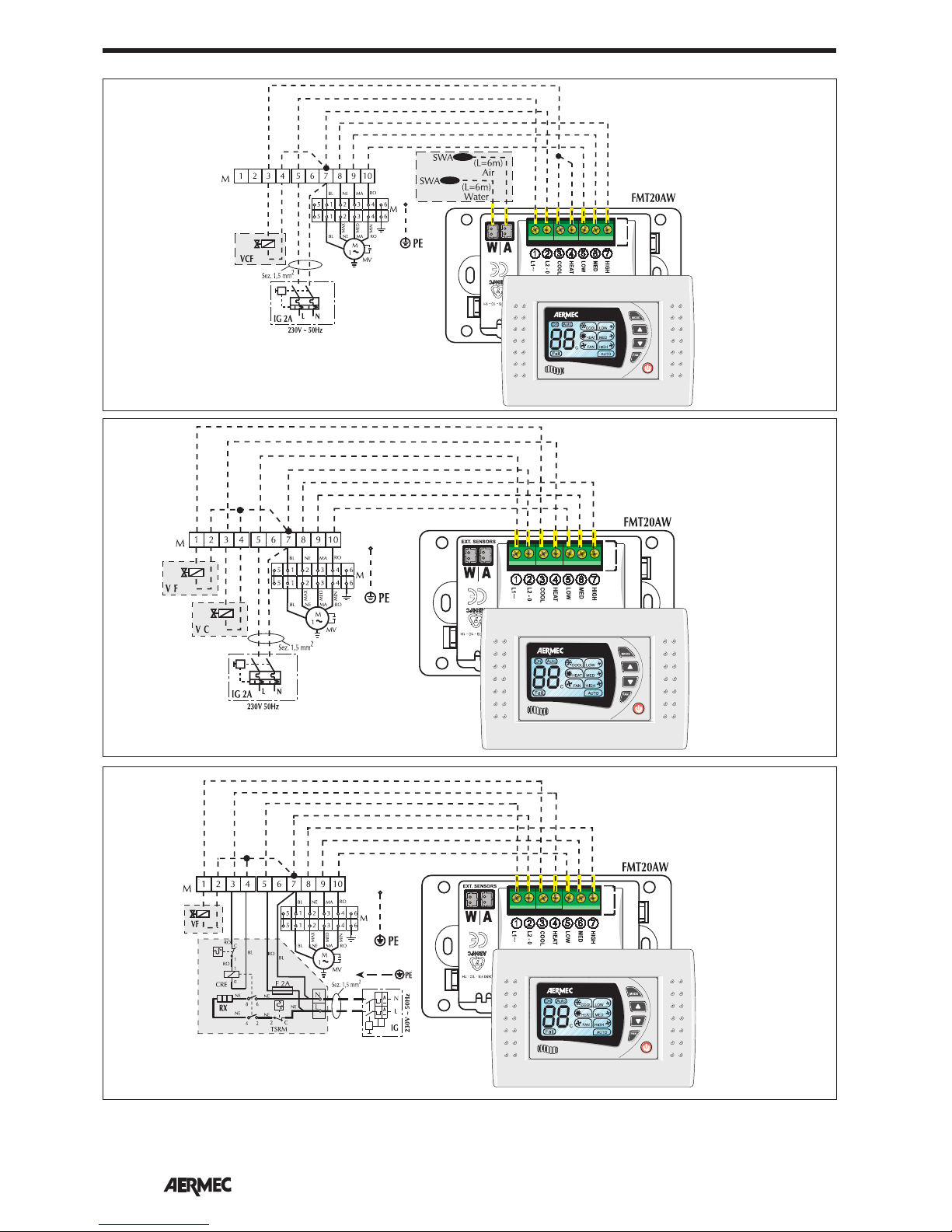
VEC
FMT20 + VCF
2 tubi
2 tube
2 tuyaux
2 Röhren
2 tubos
VEC
FMT20 + VF + VC
4 tubi
4 tube
4 tuyaux
4 Röhren
4 tubos
VEC
FMT20 + VF + RX
2 tubi
2 tube
2 tuyaux
2 Röhren
2 tubos
SCHEMI ELETTRICI • WIRING DIAGRAMS • SCHEMAS ELECTRIQUES • SCHALTPLÄNE • ESQUEMAS ELÉCTRICOS
Page 37
37
English
230V ~ 50Hz
M
1 2 3 4 5
L
6
N
7 8 9 10
PE
VCH
IG
M
1 2 3 4 5 6 7 8 9 10
VCH
4A
FCX/1
FCX/2
V1
V2
V3
V1
V2
V3
PH
L
N
N
SIT5
Y1
Y2
Y1
Y2
F 1A
M
1 2 3 4 5 6 7 8 9 10
VCH
FCX/N
M
1
MV
BL NE MA RO
MIN
MED
MAX
5
5
1 4
4
3
3
2
2
6
6
1
BL NE MA RO
V1V2V3
V1
V2
V3
L
N
N
PH
SIT3/1
F
2A
INPUT
OUTPUT
MS
MS
INPUT
OUTPUT
V1
V2
V3
V1
V2
V3
L
N
N
PH
SIT3/2
F
2A
INPUT
OUTPUT
V1V2V3
V1
V2
V3
L
N
N
PH
SIT3/10
F
2A
INPUT
OUTPUT
MS
M
1
MV
BL NE MA RO
MIN
MED
MAX
5
5
1 4
4
3
3
2
2
6
6
1
BL NE MA RO
M
1
MV
BL NE MA RO
MIN
MED
MAX
5
5
1 4
4
3
3
2
2
6
6
1
BL NE MA RO
L = 15m MAX
PXAE
+
-
SA (INT)
N
L
V1
Y1
V3
V2
Y2
CECEMS
MS
SW
SW
M1
JP1
EXT
INT
Gli schemi elettrici sono soggetti ad un continuo aggiornamento, è obbligatorio quindi fare riferimento a quelli a bordo macchina.
All wiring diagrams are constantly updated. Please refer to the ones supplied with the unit.
Nos schémas électriques étant constamment mis à jour, il faut absolument se référer à ceux fournis à bord de nos appareils.
Die Schaltpläne werden ständig aktualisiert, deswegen muss man sich stets auf das mit dem Gerät gelieferte Schaltschema beziehen.
El cableado de las máquinas es sometido a actualizaciones constantes. Por favor, para cada unidad hagan referencia a los esquemas suministrados con la misma.
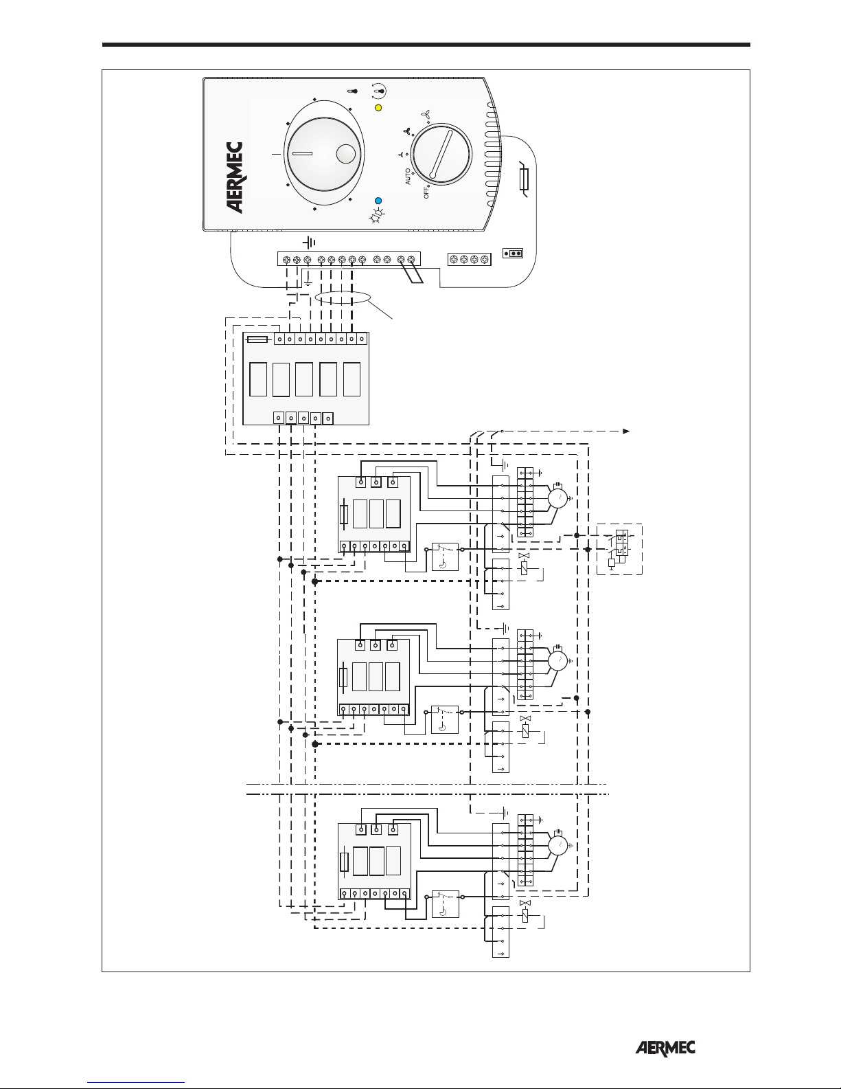
VEC
PXAE
SIT3 + SIT5
SCHEMI ELETTRICI • WIRING DIAGRAMS • SCHEMAS ELECTRIQUES • SCHALTPLÄNE • ESQUEMAS ELÉCTRICOS
Page 38
38
English
PROBLEM
Insufficient air flow at outlet
Unit does not heat
Unit does not cool
Fan not turning
Condensation forming on
the external case of the
unit
PROBABLE CAUSE
Incorrect speed setting on control panel
Blocked filter
Obstructed air flow (inlet and/or outlet)
No hot water
Incorrect control panel setting
No cold water
Incorrect control panel setting
No electrical power
Water has not reached the operating temperature
Air has not reached the operating temperature
Temperature and humidity limits specified by
“MINIMUM AVERAGE WATER TEMPERATURE” have
been reached
SOLUTION
Select the correct speed on the control
panel
Clean the filter
Remove the obstacle
Check the boiler
Check the heat pump
Set the control panel correctly
Check the chiller
Set the control panel
Check that there is electrical power
Check the boiler or chiller and/or its setting
Check the temperature set on the thermostat
Raise the water temperature above the limits
specified by “MINIMUM AVERAGE WATER
TEMPERATURE”
For any problems not listed, contact the After Sales Service immediately.
TROUBLESHOOTING
Interventions:
- External cleaning, weekly, to be carried
out with a damp cloth (
dipped in water
maximum 40°C)
and neutral soap; avoid
any other type of detergent or solvent.
- Do not spray water on the outer or
inner surfaces of the fan coil (this could
cause short-circuiting).
- Visual inspection of the state of the fan
coil for every maintenance operation;
any anomaly must be reported to the
After Sales Service.
MAINTENANCE
Routine maintenance can be carried out
by the user: it involves a series of simple
operations, thanks to which the fan coil
can operate at its maximum efficiency
level.
Before carrying out any work, make
sure the electricity supply is unplugged.
Do not remove the shell or the
mechanical/electrical protection
devices.
Interventions:
- Internal cleaning, once a year or before the machine is shut
down for a long period. In rooms where a high level of air
cleaning is requested, the cleaning intervention can be made
more often. It consists in the cleaning of the coil, fan louvres,
basin, ioniser, and all the parts in contact with the treated air.
Check also the condition of the filter, cleaning or replacing it if
necessary.
Do not use jets or sprays of water during the cleaning.
Use the brush to remove any dust deposits.
- Repairs and fine tuning: if you notice anomalies, consult the
“TROUBLESHOOTING" chapter of this manual before contacting the After Sales Service.
Extraordinary maintenance must only
be carried out by Aermec After Sales
Service centres, or by technicians with
the technical and professional requisites
for the installation, transformation,
amplification and maintenance of the
systems, and able to check these aspects
in terms of safety and good working.
For the electrical wiring in particular,
checks relating to the following aspects
are required:
- Measurement of the electrical system
insulation resistance;
- Continuity test of the protection wires.
Extraordinary maintenance consists of a
set of complex operations that involve
the dismantling of the fan coil or its
components, resulting in the restoration
of the fan coil's functioning at maximum
efficiency.
Before carrying out any work, make
sure the electricity supply is unplugged.
ORDINARY MAINTENANCE
EXTRAORDINARY MAINTENANCE
Page 39
Aermec S.p.A.
I-37040 Bevilacqua (VR) - Italy
Via Roma, 44 - Tel. (+39) 0442 633111
Telefax (+39) 0442 93730 - (+39) 0442 93566
www .aermec. com
The technical data in this document are not binding.
Aermec S.p.A. reserves the right to introduce any modifications deemed necessary for the improvement of the product, at any time.
Les données mentionnées dans ce manuel ne constituent aucun engagement de notre part. Aermec S.p.A. se réserve le droit de modifier à tous moments les
données considérées nécessaires à l’amelioration du produit.
The technical data in this documentation are not binding.
Aermec S.p.A. reserves the right to make whatever modifications it deems necessary to improve the product at any time.
Im Sinne des technischen Fortschrittes behält sich Aermec S.p.A. vor, in der Produktion Änderungen und Verbesserungen ohne Ankündigung durchzuführen.
Los datos técnicos indicados en la presente documentación no son vinculantes.
Aermec S.p.A. se reserva el derecho de realizar en cualquier momento las modificaciones que estime necesarias para mejorar el producto.
Aermec partecipa al Programma di Certificazione EUROVENT. I prodotti interessati figurano nella Guida EUROVENT dei Prodotti Certificati.
Aermec adheres to the EUROVENT Certification Programme. These products are listed in the EUROVENT Directory of Certified Products.
Aermec partecipe au Programme de Certification EUROVENT. Les produits figurent dans l’Annuaire EUROVENT des Produits Certifiés.
Aermec ist am Zertifikations - Programm EUROVENT beteiligt. Die entsprechend gekennzeichneten Produkte sind im EUROVENT - Jahrbuch aufgeführt.
AERMEC S.p.A. participa en el programa de certificación EUROVENT. Sus equipos aparecen en el directorio de productos certificados EUROVENT.
 Loading...