


ROOF-TOP UNITS R410A - Manual selection, installation and maintenence
RTE
240-400
GB
1102. 6180892_00

AERMEC S.p.A.
37040 Bevilacqua (VR) – Italy
Via Roma, 996
Tel. (+39) 0442 633111
www
.aermec. com
1115
DICHIARAZIONE DI CONFORMITA’
DECLARATION OF CONFORMITY
DÉCLARATION DE CONFORMITÉ
KONFORMITÄTSERKLÄRUNG
Tipo macchina / Type of unit / Type
de machine / Maschinentyp
Condizionatore d'aria tipo Roof-top, Roof-top air conditioning unit
Unité de climatisation Roof-top, Autonome Klimaanlage
Modello / Model / Modèle / Modell
Matricola / Serial No /
Numéro de série / Seriennummer
La macchina è conforme alle disposizioni contenute nelle seguenti direttive: / The unit complies with the
provisions contained in the following directives: / La machine est conforme aux dispositions contenues
dans les directives suivantes: / Das Gerät entspricht den Bestimmungen der folgenden Richtlinien
enthaltenen:
2006/42/CE Direttiva Macchine / Machine Directive / Machine Direct ive / Mas ch inenr ic htlinie
2006/95/CE Direttiva Bassa Tensione / Low voltage Directive / Basse Tension / Niederspannungsrichtlinie
2004/108/CE Direttiva EMC / EMC Directive / EMC Directive / EMV-Richtlinie
97/23/CE Direttiva PED / PED Directive / PED Directive / PED- Ric htlinie
ed è stato sottoposto alla procedura di valutazione A1 con controlli dell’organismo Società Consortile
PASCAL a r.l. (n° 1115) via A. Scarsellini, 13 – 20161 Milano (certificato n° 20 del 10/02/2003)
has been evaluated according to the A1 procedures with controls carried out by PASCAL (n°1115)
company, address A. Scarsellini 13, 20126 Milan (certificate n°20 dated 10/02/2003)
et a été vérifiée selon la procédure A1 par l’organism Società Consortile PASCAL a r.l. (n° 1115) via A.
Scarsellini, 13 – 20161 Milano (certificat n° 20 date 10/02/2003)
wurde überwacht nach Beobachtung Unternehmen PASCAL (n°1115), Adresse A. Scarsellini 13, 20126
Mailand (Zertifikat n°20 von 10/02/2003
Componente / Component / Élément / Komponente Modulo / Module / Module / Modul
Pressostato di alta pressione / Pressure switch / Pressostat / Druckschalter B + D
Valvola di sicurezza / Pressure relief valve / Valve de sécurité / Sicherheitsventil B + D
Compressore / Compressor / Compresseur / Kompressor D1
Ricevitore di liquido / Liquid receiver / Flüssigkeitssammler / Boutilles liquide A
Separatore di liquido / Suction accumulator / Flüssigkeitsabscheider / Boutilles anti-coup A
Filtro deidratatore / Filter / Filter / Filtres A
Rubinetti / Ball valve / kleinventile / Vanes A
Batteria di scambio termico / Coil / Register / Batterie A
La persona autorizzata a costituire il fascicolo tecnico è: / The person authorized to compile the technical
file is: / La personne autorisée à constituer le dossier technique est: / Die Person berechtigt, die
technischen Unterlagen zusammenzustellen:
Giampaolo Cardin via Luppia Alberi,170
Bevilacqua, 25/01/2011 Luigi Zucchi

Index
General norm 4
Units identification and description 5
Version cambination 6
Unit configuration 7
Description of components 10
Regulation system 11
Accessories 12
Technical data 14
Operating limits 20
Sound data 20
Cooling capacity and input power 21
Heating capacity and input power 22
Corrective coefficients for different flow rates 23
Total capacities for different relative humidities 23
Performance tables for water heating coils 24
Technical data generator Gxxx 25
List of pressure equipment - Directive PED 97/23 CE 26
Refrigerant circuits 26
Dimensions 28
Nominal dimensions 32
Refrigerant charge 32
Weights 33
Configurations 34
RTE with three-way mixing box 35
RTE with heat recovery unit 35
RTE with heat generators G72 - G92 - G150 kW 37
PR2 remote panel 38
Installing and using the unit 39
Norms covering the use of R410A gas 40
Hydraulic connections - Condensate drain pain 40
Connection aeraulic 41
Joining RTE sections 42
Improper use 43
Electrical wiring 43
Security 44
Unit maintenance 44
Monthly maintenence program 45
Diagnosis and fault solving 46
English

General norms
Roof-top units - RTE series-
This manual is an integral
part of the documentation
enclosed with the unit.
It must be preserved for
future reference and must
accompany the machine throughout its
life.
The manual defines the purpose for
which the machine has been built and
establishes its correct installation and
the limits of its use.
• This manual provides all the
technical instructions and
instructions for the installation
of this unit and the main accident
prevention regulations.
Read carefully and thoroughly all the
information referred to in this manual.
Pay particular attention to the usage
instructions accompanied by the words
"DANGER" or "WARNING" because, if
not observed, they can cause damage
to the machine and/or property and/or
injury to people.
If any malfunctions are not included
in this manual, contact the local After
Sales Service immediately.
• AERMEC S.p.A. declines all liability
for any damage due to improper
use of the machine or the partial or
superficial reading of the information
contained in this manual.
• Installation and maintenance
must be carried out by trained
and qualified personnel, having
the requirements laid down by
law 46/90 and/or DPR 380/2001
for electric/electronic and air
conditioning installations, with
consequent registration at the
local CHAMBER of COMMERCE.
Otherwise AERMEC S.p.A. decline
all responsibility regarding the safety
of the product.
THE MANUFACTURER DECLINES ALL
LIABILITY FOR DAMAGE TO THINGS
OR INJURY TO PERSONS AND
ANIMALS CAUSED BY THE FAILURE
TO OBSERVE THE INSTRUCTIONS
AND STANDARDS IN THIS MANUAL.
Even though during the design phase of
the RTE unit adequate assessment of the
risks was made, pay ATTENTION to the
pictograms on the machine that helps
the reading the manual by drawing the
reader's attention rapidly to the risk
situations that cannot be avoided or
sufficiently limited by using measures
and technical means of protection.
GENERAL HAZARD SIGNAL
Carefully adhere to all the
indications next to the icon.
Failure to comply with the instructions
may generate hazardous situations
with possible damage to the health
of the operator and user in general.
DANGEROUS ELECTRICAL
VOLTAGE SIGNAL
Carefully adhere to all the
indications next to the icon.
The signal indicates components of the
unit or, in this manual, specifies actions
that could generate electrically-related
risks.
GENERAL PROHIBITION
SIGNAL
Carefully adhere to all the
indications next to the icon that limit
actions in order to guarantee better
operator safety.
IT IS PROHIBITED TO
CLEAN, OIL AND GREASE,
repair or manually adjust
parts in motion.
INFLAMMABLE MATERIAL.
MAIN WARRANTY
CONDITIONS
• The warranty does not include
payment for damage due to the
incorrect installation of the unit by
the installation engineer.
• The warranty does not include
payment for damage due to the
improper use of the unit by the user.
• The manufacturer does not consider
itself liable for accidents to the user
or the installer due to the incorrect
installation or improper use of the
unit.
The warranty is not valid when:
• the services and the repairs have
been carried out by non-authorised
personnel or companies;
• the unit has been repaired or
modified in the past with non OEM
spare parts;
• the unit has not been adequately
maintained;
• if the instructions described in this
manual have not been followed;
• if non-authorised modifications have
been made.
Note:
The Manufacturer reserves the right at
all times to make any modification for
the improvement of its product and is
not obliged to add these modification
to machines of previous manufacture
that have already been delivered or are
being built.
The warranty conditions are any
subject to the general sales conditions
at the moment the contract is finalised.
Manual selection, installation and maintenance
4

Roof-top units - RTE series-
The RTE rooftop units are identified
by means of a product identification
code created by the selection program
AERMECPro. A product identification
code example is the following:
Units identification and description
RTE240F001600000000000
For further information, please refer to
the selection program.
Unit description
The “ ROOFTOP “ units of the RTE series
have been designed taking into account
the precise requirements in the system
necessary for treating large air volumes,
typical of supermarket and hypermarket
buildings and environments for shows, fairs
and industrial uses in general.
These units are usually situated on the roofs
or anyway in the open air, offering these
main advantages:
• because they are installed on the roof
they do not take operational space away
from the room;
• they offer the maximum modularity,
therefore making it possible to differentiate
the treatments in different volumes with
different destination characteristics (food,
clothing department etc.);
• they offer high levels of environmental
comfort by controlling the exchange,
filtering and humidification or
dehumidification of the air in addition to
the temperature;
• the environmental noise level is kept low due
to the careful soundproofing of the machine.
Components
The RTE Rooftop units are all available in
the cooling only version (RTE F) or in heat
pump version (RTE H).
RTE units are equipped with an adhesive label that summarizes the main technical data such as model, heat output
and cooling capacity, rated capacity of
the air in recovery and extraction and
electrical data.
For any future reference and for all
communication with the AERMEC SpA
must indicate the number.
In addition, each piece is accompanied
by targhettta with weight and other
information traceability.
The rating plate and the plate of the
weight of the package are applied outside the main rooftop, on the side panel
near the electrical panel inspected the
same.
The plate of the weight of each package
is applied externally on the panel additional inspections, or packaging.
The rooftop RTE units come complete with :
• condenser unit with 6 pole axial fans and
scroll compressors;
• complete refrigeration circuit complete
with thermostatic valve, filters, sight glass;
• synthetic undulated filter class G4
(EN779);
• direct expansion coil with aluminium
condensate drain pan;
• radial supply fan with forward-curved
blades with belt and variable pulley
transmission;
• microprocessor control complete with
sensors and actuators;
• electrical panel;
Sizes
The units in the RTE series are available in
four sizes (240-260-300-350 -400) each of
which with the possibility of standard, low
noise L (excluding 350 and 400) or high
temperature operation mode A (excluding
350 and 400). By aptly combining the
several available options, it is possible to
configure each model in such a way as to
meet the specific of system requirements.
The RTE Series rooftop units are identified
by a commercial speaker symbol generated directly from the breeding program. An
example of an acronym speaker is as follows:
RTE260FA0A000PD00P00000
For more information, refer to the selection
program.
The table in fig.01 shows how to make up
the commercial code with twenty-four fields,
representative of the available options.
Available versions
N.B. the figures shown refer to the
dimensional specifications on pages 27-29.
STANDARD CONFIGURATION: consists of
the single block rooftop module with G4 flat
filters (efficiency according to EN779), direct
expansion coil (hot coil optional) (fig.1)
SMP : rooftop with 2-way mixing box rear
NOTE:
(1) Damper without actuators and
recirculation damper upon request.
(1)
exhaust
SM2: rooftop with 2-way mixing box side/
bottom exhaust
SM3: rooftop with 3-way mixing box with
temperature free-cooling (fig. 7)
FT7: rooftop with panel pre-filters G3 and
rigid bag filters F7 (EN779) (fig.3)
REC: rooftop with plate type heat recovery
section and exhaust fan. The cross-flow
heat recuperator allows the sensible heat
recovery from the exhaust air with a winter
operation efficiency over 50%. The two air
flows (supply and exhaust) are completely
separated and therefore all types of
contamination are avoided. (fig.13)
G72, G92, G150: rooftop with condensation
heat generator with rated heating capacity
of 72 kW
condensation generator is fed by methane
gas. The air is heated through the passage
over the surface of the combustion chamber
and heat exchanger pipes. The combustion
chamber is fully made of AISI 430 stainless
steel, while the surfaces in contact with
the condensate (exchanger, fume hood)
are made of AISI 304 L stainless steel to
give outstanding resistance to corrosion. It
is provided with an automatic reset safety
thermostat (fig.6).
(fig.2)
(1)
(2)
, 92 kW or 150 kW. The hot air
Air heater model
G72
G92
G150
(fig.4)
RTE
Methane gas
consumption
G20 (15°C 1013 mbar)
2,3 - 8,3 mc/h
3,2 - 10,4 mc/h
4,7 - 16,4 mc/h
R410A
RTE
Manual selection, installation and maintenance
5

Version combinations
SM2-FT7: rooftop with 2-way mixing box,
side/bottom exhaust and bag filters F7
(fig.5)
G72-SMP: rooftop with 72kW heat
generator and 2-way mixing box rear
exhaust (fig.8)
(1)(2)
G72-FT7: rooftop with 72 kW heat
generator and bag filters F7 (fig.9)
G92-SMP: rooftop with 92kW heat
generator and 2-way mixing box rear
exhaust (fig.8)
G92-FT7: rooftop with 92 kW heat
generator and bag filters F7 (fig.9)
G150-SMP: rooftop with 150kW heat
generator and 2-way mixing box rear
exhaust (fig.8)
G150-FT7: rooftop with 150 kW heat
generator and bag filters F7 (fig.9)
SM3-FT7: rooftop with 3-way mixing box
and bag filters F7 (fig.10)
SM2-G72:
and
rooftop with 72kW heat generator
2-way
mixing box (fig.11)
(1)(2)
SM2-G92: rooftop with 92kW heat
generator and 2-way mixing box (fig.11)
SM2-G150: rooftop with 150kW heat
generator and 2-way mixing box (fig.11)
SM2-G72-FT7: rooftop with 72kW heat
generator, 2-way mixing box and bag filters
F7 (fig.12)
(1)(2)
SM2-G92-FT7: rooftop with 92kW heat
generator, 2-way mixing box and bag filters
F7 (fig.12)
(1)
SM2-G150-FT7: rooftop with 150kW heat
generator, 2-way mixing box and bag filters
F7 (fig.12)
(1)
REC-FT7: rooftop with static heat recovery
unit and bag filters F7 (fig.14)
SM3-G72: rooftop with 72kW heat
generator and 3-way mixing box (fig.15)
SM3-G92: rooftop with 92kW heat
generator and 3-way mixing box (fig.15)
SM3-G150: rooftop with 150kW heat
generator and 3-way mixing box (fig.15)
(1)
(2)
(1)
(1)
(2)
Version combinations
SM3-G72-FT7: rooftop with 72kW heat
generator, 3-way mixing box and bag filters
F7 (fig.16)
SM3-G92-FT7: rooftop with 92kW heat
generator, 3-way mixing box and bag filters
F7 (fig.16)
SM3-G150-FT7: rooftop with 150kW
heat generator, 3-way mixing box and bag
filters F7 (fig.16)
REC-G72: rooftop with static heat recovery
unit and 72kW heat generator (fig.17)
REC-G92: rooftop with static heat recovery
unit and 92kW heat generator (fig.17)
REC-G150: rooftop with static heat
recovery unit and 150kW heat generator
(fig.17)
REC-G72-FT7: rooftop with section with
heat recovery unit, 72kW heat generator
and bag filters F7 (fig.18)
REC-G92-FT7: rooftop with crossflow
recovery unit, 92kW heat generator, and
bag filters F7 (fig.18)
REC-G150-FT7: rooftop with crossflow
recovery unit, 150kW heat generator, and
bag filters F7 (fig.18)
(1)()
NOTE:
(1) dampers without actuators
(2) not available for sizes 260 - 300 - 350 - 400
e.g.: (REC+G72+FT7) is an example of version
combination. To see the sizes, refer to the sizes
chapter (page 25).
Roof-top units - RTE series-
(2)
Manual selection, installation and maintenance
6

Unit configuration
Roof-top units - RTE series-
Field 1, 2, 3,4
Field 5, 6, 7
Field 8 Versions
Field 9 Operation
Field 10 Power supply
Field 11 Versions and combinations (THE FIGURES INDICATED REFER TO THE SIZES FROM PAGE 25 TO 28)
RTE
240
260
300
350
400
F cooling only
H heat pump
0 Standard
L Low-noise operation (no 350 and 400)
A High temperature (no 350 and 400)
O ° 3~ 400 V -50 Hz (standard)
W TV2 3~ 230 V -50 Hz
Z TV3 3~ 460 V -60 Hz
0 ° Basic configuration (Fig. 1)
1 SMP 2-way mixing box rear exhaust (Fig.2) (1)
2 FT7 Bag filters F7 (Fig. 3)
A SM2 2-way mixing box side/bottom exhaust (Fig.4) (1)
B SM2-FT7 2-way mixing box, side/bottom exhaust and bag filters (Fig.5) (1)
C G72 Heat generator 72 kW (Fig. 6) (4)
D G92 Heat generator 92 kW (Fig. 6)
3 G150 Heat generator 150 kW (Fig. 6) (5)
E SM3 3-way mixing box with ventilator fan (Fig. 7 on dimensional indications)
F G72-SMP 72 kW heat generator and 2-way mixing box rear exhaust (fig.8) (4)
G G92-SMP 92 kW heat generator and 2-way mixing box rear exhaust (Fig.8)
4 G150-SMP 150 kW heat generator and 2-way mixing box rear exhaust (Fig.8) (5)
H G72-FT7 72 kW heat generator and bag filters F7 (Fig.9) (4)
I G92-FT7 92 kW heat generator and bag filters F7 (Fig.9)
5 G150-FT7 150 kW heat generator and bag filters F7 (Fig.9) (5)
J SM3-FT7 3-way mixing box with bag filters F7 (Fig.10)
K SM2-G72 72kW heat generator and two-ways mixing box(Fig.11) (1)(4)
L SM2-G92 2-way mixing box with 92kW heat generator (Fig.11) (1)
6 SM2-G150 2-way mixing box with 150kW heat generator (Fig.11) (1) (5)
M SM2-G72-FT7: 2-way mixing box with 72kW
N SM2-G92-FT7: 2-way mixing box with 92kW
7 SM2-G150-FT7: 2-way mixing box with 150kW
P REC
Q REC-FT7
R SM3-G72 3-way mixing box with
S SM3-G92 3-way
8 SM3-G150 3-way
T SM3-G72-FT7 3-way mixing box with
U SM3-G92-FT7 3-way
9 SM3-G150-FT7 3-way
V REC-G72
Y REC-G92
Z REC-G150
X REC-G72-FT7
W REC-G92-FT7
O REC-G150-FT7
Section with crossflow plate heat recuperator (Fig. 13)
Section with crossflow plate heat recuperator and bag filters F7 (fig.14)
mixing box with 92kW heat generator (Fig.15)
mixing box with 150W heat generator (Fig.15) (5)
mixing box with 92kW heat generator and bag filters F7 (Fig.16)
mixing box with 150kW heat generator and bag filters F7 (Fig.16) (5)
Section with crossflow plate heat recuperator and 72kW heat generator (Fig.17) (4)
Section with crossflow plate heat recuperator and 92kW heat generator (Fig.17)
Section with crossflow plate heat recuperator and 150kW heat generator (Fig.17) (5)
Section with crossflow plate heat recuperator, 72kW heat generator, and bag filters F7(fig.18)(4)
Section with crossflow plate heat recuperator
Section with crossflow plate heat recuperator
heat generator and bag filters F7(Fig.12)
heat generator and bag filters F7 (Fig.12)
heat generator and bag filters F7 (Fig.12)
72kW heat generator (Fig.15)
72kW heat generator and bag filters F7 (Fig.16)
, 92kW heat generator, and bag filters F7(fig.18)
, 150kW heat generator, and bag filters F7(fig.18) (5)
(4)
(1)(4)
(1)
(1) (5)
(4)
(1) = Dampers without actuators
(2) = The right or left direction refers to the direction of air flow inside the air handling sections
(3) = The coil to water connection side is always on the left
(4) = 72 kW Generator only available on RTE 240
(5) = No RTE 240 model
Manual selection, installation and maintenance
7

Roof-top units - RTE series-
Field 12
Field 13 Heating coil accessory
Field 14 Outside coil treatment accessory
Field 15 Air intake accessory
Field 16 Air supply accessory
Filter pressure switch /coil protection grille accessory
0 ° No accessory of the PF/GP type
2 BP Heat recovery unit with by-pass (option only valid if field 10 =
3 PF Filter pressure switch
4 GP Condenser protection grille
5 PF+GP
6 BP+PF (option only valid if field 10 =
7 BP+GP (option only valid if field 10 = P, Q, V, Y, Z, X, W, O)
8 BP+PF+GP (option only valid if field 10 = P, Q, V, Y, Z, X, W, O)
0 ° No battery
W BTR Two-row hot-water heating coil with three-way modulating valve (3)
E BRE 12 Two stages electric heating coil (12 kW)
F BRE 18 Two stages electric heating coil (18 kW)
G BRE 24 Two stages electric heating coil (24 kW)
H BRE 36 Two stages electric heating coil (36 kW)
0 ° Coils with copper pipes and aluminium fins
A BSP Coil with copper pipes and pre-painted aluminium fins
B BSR Coil with copper pipes and copper fins
C BSS Coil with copper pipes and tin-plated copper fins
0 ° Std. rear return air intake. If there is a return fan, the head is up to 150 Pa
(value always 0 when field
M T1 Right side return air intake, rear fresh air intake
(option only valid if field 10 = A, B, K, L, M, N, 6, 7) (2)
N T2 Left side return air intake, rear fresh air intake
(option only valid if field 10 = A, B, K, L, M, N, 6, 7) (2)
P T3 Rear return and fresh air intake
(option only valid if field 10 = A, B, K, L, M, N, 6, 7) (2)
Q T4 Bottom return air intake, rear fresh air intake
(option only valid if field 10 = A, B, K, L, M, N, 6, 7) (2)
T T5 Right side return air intake, left side fresh air intake
(option only valid if field 10 = A, B, K, L, M, N, 6, 7) (2)
U T6 Left side return air intake, left side fresh air intake
(option only valid if field 10 = A, B, K, L, M, N,) (2)
R AI Bottom air intake, return fan available pressure up to 150 Pa
(option valid only if field 10 =E, J, R, S, T, U, 8, 9)
S AS Top air intake, return fan available pressure up to 150 Pa
(option valid only if field
W PA4 Rear air intake, return fan available pressure up to 300 Pa
(option valid only if
Z Al+PA4 Bottom air intake, return fan available pressure up to 300 Pa
(option valid only if field
V As+PA4 Top air intake, return fan available pressure up to 300 Pa
(option valid only if field
0 ° Bottom air supply, supply fan available pressure up to 200 Pa (standard)
D MA Top air supply, supply fan available pressure up to 200 Pa
E MS Left side air supply, supply fan available pressure up to 200 Pa (2)
F MD Right side air supply, supply fan available pressure up to 200 Pa (2)
G PM4 Bottom air supply, supply fan available pressure up to 400 Pa
H MA+PM4 Top air supply, supply fan available pressure up to 400 Pa
I MS+PM4 Left side air supply, supply fan available pressure up to 400 Pa (2)
L MD+PM4 Right side air supply, supply fan available pressure up to 400 Pa (2)
P, Q, V, Y, Z, X, W, O)
P, Q, V, Y, Z, X, W, O)
10 = 0, 1, 2, C, D, F, G, H, I, P, Q, V, Y, X, W)
10 =E, J, R, S, T, U, 8, 9)
field 10 = E, J, P, Q, R, S, T, U, V, Y, X, W, O)
10 =E, J, R, S, T, U, 8, 9)
10 =E, J, R, S, T, U, 8, 9)
(1) = Dampers without actuators
(2) = The right or left direction refers to the direction of air flow inside the air handling sections
(3) = The coil to water connection side is always on the left
(4) = 72 kW heat generator only available on RTE 240
(5) = No RTE 240 model
Manual selection, installation and maintenance
8

Field 17 Refrigeration circuit accessories
0 ° No refrigeration circuit accessory
1 DCPR Low temperature device (external temperature down to - 20 °C) (standard on the low noise operation
2 TP Pressure transducers (standard in the heat pump version)
3 RUB Discharge and Liquid shut-off valves (for cooling only version)
4 DCPR+TP
5 DCPR+RUB
6 TP+RUB
7 DCPR+TP+RUB
Field 18 Enthalpy control accessories
0 ° No enthalpy control accessory
A PUC Humidification control provision
B FCH Enthalpic Freecooling
C DP Dehumidification and re-heating management
D PUC+FCH
E PUC+DP
F FCH+DP
G PUC+FCH+DP
Field 19 Electronic accessories
0 ° No electronic accessory
P PR2 Remote panel
S SSV RS485 interface card for supervision
Q SQA VOC air quality sensor
R PR2+SSV
T PR2+SQA
U SSV+SQA (option only valid if field 10 = E, J, O, P, Q, R, S, T, U, V, Y, Z, W, 8, 9)
V PR2+SSV+SQA (option only valid if field 10 = E, J, O, P, Q, R, S, T, U, V, Y, Z, W, 8, 9)
Field 20 Damper actuator accessory
0 ° Modulating damper actuator series for versions with SM3 and REC
1 SCSR Return air damper for SMP mixing box (if field 10 = 1, 4, F, G)
2 SCS2 Return air damper for SM2 mixing box (if field 10 = A, B, K, L, 6, M, N, 7)
3 SCM3 Modulating spring return actuator for versions with 3-way mixing box and heat recovery unit (that
4 SRP Return air damper for SMP mixing box and modulating damper actuator (if field 10 = 1, 4, F, G)
5 SR2 Return air damper for SM2 mixing box and modulating damper actuator (if field 10 = A, B, K, L, 6,
6 SCMP Return air damper for SMP mixing box and modulating spring return actuator (if field 10 = 1, 4, F,
7 SCM2 Return air damper for SM2 mixing box, modulating damper actuator on fresh air and modulating
Field 21 Shock absorbing accessory
0 ° No shock absorbers
3 VT3 Rubber shock absorbers for units in basic version
5 VT5 Rubber shock absorbers for units from the 5m to the 7.1m
7 VT7 Rubber shock absorbers for units of over the 7.1m
Field 22 Inspection side
0 SX Left-hand supply inspection side (default)
1 DX Right-hand supply inspection side (if field 15 = 0, D, F, G, H, L)
Field 23 Condensate drain side
0 SX Left-hand condensate drain side (standard)
D DX Right-hand condensate drain side
Field 24 Special requirements
0 All according to catalogue
S Unit with at least one special requirement
Roof-top units - RTE series-
units)
(option only valid if field 10 = E, J, O, P, Q, R, S, T, U, V, Y, Z, W, 8, 9)
(option only valid if field 10 = E, J, O, P, Q, R, S, T, U, V, Y, Z, W, 8, 9)
(if field 10 = E, J, R, S, T, U, V, Y, X, W); no actuators in all the other case
contain the code SM3 or REC in the version)
M, N, 7)
G)
spring damper actuator on return air (if field 10 = A, B, K, L, 6, M, N, 7)
(if field 15 = 0, D, F, G, H, L)
(1) = Dampers without actuators
(2) = The right or left direction refers to the direction of air flow inside the air handling sections
(3) = The water coil connection side is always on the left
(4) = 72 kW Generator only available on RTE 240
(5) = No RTE 240 model
Manual selection, installation and maintenance
9

Roof-top units - RTE series-
Refrigeration
Description of components
circuit
Compressors
Scroll-type hermetic compressors with
crankcase heater provided as a standard in the
heat pump version (and in the only coolung
version, if provided with DCPR accessory)
Provided the unit is under voltage the heating
element is automatically switches on when the
unit stops.
Internal heat exchanger
Made with copper pipes and aluminium
fi ns locked into place through mechanical
expansion of the pipes. The coil is of the high
effi ciency type; grooved pipes and corrugated
fi ns.
External heat exchanger
Made with copper pipes and aluminium
fi ns locked into place through mechanical
expansion of the pipes. The coil is of the high
effi ciency type; grooved or smooth pipes
according to the size.
Liquid receiver
(only for heat pump version)
Safety valve
Set to 30 bar, it protects the circuit against
excessive pressures.
Check valve (only for heat pump version)
The valve allows the refrigerant to fl ow in one
direction only.
Frame and fans
Thermostatic valve
The valve with external equaliser on the
evaporator outlet, modulates the gas fl ow to
the evaporator according to the heat load in
such a way as to assure a suffi cient degree of
overheating at the intake gas.
Drier-fi lter
Made of ceramics and hygroscopic material it
traps impurities and any traces of humidity in
the cooling circuit.
Sight glass
To check the refrigerating gas charge and verify
presence of humidity in the cooling circuit.
Solenoid valve
Switches on after the compressor has stopped,
interrupting the migration of the liquid
refrigeration gas to the evaporator.
Liquid and discharge shut-off valves (accessory
only available for the cooling only versions).
They stop the refrigerant fl ow in case of
extraordinary maintenance.
4-way valve (only for heat pump version)
To control the refrigerant fl ow for the summer/
winter mode changeover and to operate the
defrosting cycles.
Solenoid by-pass valve
(only for heat pump version)
The valve by-passes the thermostatic valve
during the defrosting cycles.
Condensing section
It is provided with statically and dynamically
balanced axial fans. The fans are provided of
protection grilles while the electric motors
are protected by means of magnetothermal
switches.
Air handling section
It is provided with a double intake radial
fan with forward curved blades for better
performance and quietness. The fan is driven
by a three phases electric motor with belts and
adjustable pulleys.
Structure
The air handling section is made of 50
mm thick sandwich panels with type of
construction for the air treatment side is:
external peraluman sandwich-type panelling
and galvanised steel 50 mm thick inside with
injected polyurethane insulation (thickness 42
kg/m3). Accessible panels are provided with
proper knobs, while the others are set through
screws.
Control and safety
components
Door lock switch
For safety the electrical panel can only be
accessed by cutting off the power using the
opening lever on the panel itself. This lever
can be locked in place using one or more
padlocks, during maintenance in order to
prevent the machine being powered up
accidentally.
Control keyboard and display on the machine
This allows the complete control of the unit.
For a detailed description refer to the user
manual.
Electrical panel
Contains the power section and the
management of the controls and safety
devices. This conforms with standard CEI
60204-1, and electromagnetic compatibility
directives EMC 89/336/EEC and 92/31/EEC.
Antifreeze sensor (only with BTR)
When the water temperature is below +5°C,
the dedicated software, in the control card,
completely opens the three-way valve,
thereby circulating hot water through the
digital output signal.
Refrigerator circuit pressure switches
These are placed one on the high-pressure
side and one on the low pressure side of the
refrigeration circuit. They stop compressor
from operating in the case of abnormal
operating pressures.
Flow switch
This has the task of ensuring that air circulates
in the air handling section. If there is no air, it
switches off the unit.
High and low pressure transducers
(standard on the heat pump version)
Placed on the high- and low-pressure sides of
the refrigerator circuit making it possible to
show the value of the pressure on the display.
Optional on the cooling only versions.
Manual selection, installation and maintenance
10

The architecture of the microprocessor
control (fig. 02) provides for:
• a BASE CARD with microprocessor
dedicated to the execution of the
control program, provided with
display, keyboard and LED to allow
for the programming of the set-points
and the basic user operations (on/off,
display of checked values, optional
print-out ).
Roof-top units - RTE series-
Regulation system
• the program is written on the
EPROM while the set-points set are
memorised permanently on EPROM,
so that they can be kept even when
there is no power (without the need
for a support battery).
It is possible to connect the basic
card with the pLAN local network
(pCO Local Area Network) consisting
of different basic cards and terminals.
Each board can exchange data
(any parameter, whether digital or
analogue, depending on the program)
at high transmission speeds. Up to
sixteen units can be connected
(between cards and terminals) for a
maximum of 5 rooftops in such a way
as to share the information quickly.
The connection through the serial
supervision/remote assistance line in
accordance with the RS485 standard,
is made through optional serial cards
and MODBUS communication
protocol.
RT- 5.1
RT+5.1
GND5.2
-XTXR
+XTXR
DNG
6J
NALT
DNG
8J
82 2.3
84 2.3
89 4.4
86 2.5
82 2.6
87 2.6
88 3.4
82 3.4
1ON
2ON
3ON
4ON
5ON
5
1
C
9
J
4C
01J
C
5
C
N
11J
7J
5J
CLOCK CARD
built-in terminal
SERIAL CARD
1J
2
J
3
J
4J
Thanks to its versatile software, the
user terminal permits:
• to modify the basic set points at any
moment which may be protected
with a password
• the display of the detected alarms
and their acoustic detection by means
of a beeper
• the indication of the active functions
by means of leds.
• the display of all the measured
parameters.
Manual selection, installation and maintenance
0G
1B
2B
3B
CNYS
G
5.3 1
5.3 0
5.3 1
5.4 10
4B
DNG
5.4 12
5.4 13
5.5 14
5.5 9
5.5 11
1Y
FERV5
+
2
CDV42+
Y
5.6 15
3.7 6
5.2 8
1
3
D
Y
D
N
I
G
5.2 0
4.7 46
4
3DI
2DI
4.7 44
2.7 35
4.6 43
D
I5DI
D
I
2.8 36
3.5 45
4.8 30
1CDI
6
fig.02
11

DCPR - Pressure switch control device
Extends the operating range of the rooftop,
both in the summer cycle (minimum outside
air temperature to 10 ° C), and in the winter
with heat pump (maximum temperature
of outside air to 25 ° C). It also makes the
operation very quiet at part load. An
electronic control varies the speed of the fans
depending on the condensing condensing
pressure, which has a special transducer,
ensuring proper supply to the thermostatic
valve.
TP - Pressure transducers (standard on heat
pumps)
These show the high and low pressures on
a display, manage the compressor and valve
activities during defrosting and inhibit their
operation when the pressure exceeds the set
limits.
Discharge and liquid shut-off valves (only for
cooling only version).
Hermetic taps with manual closing on the
compressor supply on the circuit liquid side.
GP - Protection grills
They protect the external coils from
accidental blows and hail.
T1 - Air intake on the right side (only on the
SM2)
See page. 30.
T2 - Air intake on the left side (only on the
SM2)
See page. 30.
T3 - Rear air intake (only on the SM2)
See page. 30.
T4 - Bottom air intake (only on the SM2)
See page. 30.
AI - Bottom intake (only on the SM3)
See page. 31.
PA4 - Rear air intake
Return fan available pressure up to 300 Pa for
nominal flow rate.
MA - Upper air supply
Top air supply, supply fan available pressure
up to 200 Pa at the nominal air flowrate.
MS - Left air supply
Left air supply, supply fan available pressure
up to 200 Pa at the nominal air flowrate.
MD - Right air supply
Right air supply, supply fan available pressure
up to 200 Pa at the nominal air flowrate.
PM4 - Supply fan available pressure up to
400 Pa
Supply fan available pressure up to 400 Pa for
rated flow rate.
Accessories
BTR- Two-row heating coil
Two-row hot water coil with three way
modulating valve. These can only be
managed in the post-heating phase with the
DP accessory.
BRE- Electrical heating coil
Two-stage heating electric heating battery
provided with double safety thermostat, one
automatic resetting and the other manual
resetting. The capacities proposed are 36,
48, 60 and 72 kW (or in the order phase
indicated the capacity required). These can
only be managed in the post-heating phase
with the DP accessory.
PUC- Provision for humidification control.
ON/OFF Contact (normally open) for
humidification enabling. The unit in this
case has humidity sensor situated on the
ambient air recovery. A humidity valve is
also supplied to be positioned down line
from the humidification section.
DP - Kit for the management of the
humidification and post heating
The control will force the operation of the
compressors to dehumidify the air up to
the humidity set point set. If there is a water
or electric coil, it will also be possible to
manage the post heating.
The PUC accessory can be combined
(humidification contact).
SCS - Damper actuators for two-way
versions
Modulating actuators fitted directly on the
exhaust air damper and external damper for
the management of the air change.
SCSM damper actuators with spring return
for 2-damper-valve versions
Actuators with spring return fitted directly
on the recovery air dampers and outside
air for the management of the air change,
in case of blackout completely close the
outside air damper and open the fresh air
damper completely.
SCM3 damper actuators with spring return
for 3-damper-valve versions
Actuators with spring return mounted
directly on the dampers for the management
of the freecooling to replace the standard
ones ; in case of blackout they close the
outside air dampers completely and open
the fresh air dampers completely.
FCH - Enthalpic Free-cooling
Only with three damper mixing box.
It manages the outside air flow and recovery
referring to their enthalpic values
.
Roof-top units - RTE series-
PR2 - Remote panel
This enables rooftop control operations to be
carried out at a distance.
SSV - RS485 Serial interface for supervision
Serial card necessary for the supervision
system interface.
SQA - Air quality sensor
This analyses the quality of the air on the
basis of a mixed gas SnO2 VOC sensor by
assessing the contamination by polluting
gases. The presence of the sensor combined
with the rooftop control permits:
- the setting of a sensitivity threshold
depending on the maximum contamination
of the air predicted.
- the ventilation of the rooms only when
necessary so as to ensure energy saving.
TV2 - Power voltage 3~230V - 50HZ.
TV3 - Power voltage 3~ 460V - 60HZ.
VTR (3 - 5 - 7)- Shock absorbers
Rubber antivibration dampers. Select the VTR
model from the accessories table (see page 13).
PF - Filter dirtying pressure switch
BSP - Special batteries
Condensing coil with copper pipes and
prepainted aluminium fins.
BSR - Special coils
Condensing coil with copper pipes and
copper fins.
BSS - Special coils
Condensing coil with copper pipes and tin
plated copper fins.
Manual selection, installation and maintenance
12

Available accessories table
Roof-top units - RTE series-
Size
Version
Operation
DCPR
TP
RUB
GP
T1 (1)
T2 (1)
T3
T4
AI
PA4
MA
MS (1)
MD (1)
PM4
BTR
BRE
PUC
DP
SCS
SCSM
SCM3
FCH
PR2
SSV
SQA
TV2
TV3
VTR3 (for basic version units)
VTR5 (for units from 5 to 7.1 m)
VTR7 (for units over 7.1 m)
PF
BSP
BSR
BSS
cooling only (F) hot pump (H)
std L (no 350 and 400) A (no 350 and 400) std L (no 350 and 400) A (no 350 and 400)
o•oo•o
ooo•••
ooo- - -
oooooo
oooooo
oooooo
oooooo
oooooo
oooooo
oooooo
oooooo
oooooo
oooooo
oooooo
oooooo
oooooo
oooooo
oooooo
oooooo
oooooo
oooooo
oooooo
oooooo
oooooo
oooooo
oooooo
oooooo
oooooo
oooooo
oooooo
oooooo
oooooo
oooooo
oooooo
240 - 260 - 300 - 350 - 400
BSR oooooo
BSS
oooooo
1) = The right or left direction refers to the direction of air flow inside the air handling sections
• = standard
o = optional
- = not available
Hot water coil data (BTR accessory)
RTE Size 240 260 300 350 400
Heating capacity (kW) 400 179 200 213 219
Rows (number) 22222
Hot water coil performance referred to : inlet air 20°C; water 80/70 °C;
N.B.: for data about the water flowrate, water side pressure drops and performances with conditions different from the standard
please see page. 24
Electrical coil data (BRE accessory)
RTE Size 240 260 300 350 400
Heating capacity (kW) 12 18 24 36 12 18 24 36 12 18 24 36 12 18 24 36 12 18 24 36
Number of stages 22222
Manual selection, installation and maintenance
13

Roof-top units - RTE series-
Cooling only F (standard)
RTE
Cooling capacity F kW 77.1 88.6 103.0 129.4 142.5
Sensible cooling capacity F kW 50.1 61.2 67.0 77.7 92.6
Total input power F kW 20.7 25.3 31.8 39.7 44.5
Version 240 260 300 350 400
Energy indices
E.E.R. *
F 4.49 4.30 4.01 3.91 3.85
Condensing unit section
Compressors
Type
Number / circuit
Capacity step control
Compressor input power
L.R.A. (Locked Rotor Amps)
F scroll
F n° 2/2 2/2 2/2 2/2 2/2
F % 0-50-100 0-50-100 0-50-100 0-50-100 0-50-100
F kW 16.04 18.87 23.56 30.13 33.95
F A 350 135 175 215 215
Axial Fans
Number / Input power
Air flow rate
F n°/kW 4x0.53 4x0.53 4x0.53 4x0.56 4x0.56
Fm
3
/h 32000 29000 28000 40000 36000
Air handling section
Evaporator
Number of rows
Fn°44444
Fan
Type
Nominal air flow rate
Minimum air flow rate
Maximum air flow rate
Number
Total installed power
Available pressure with std motor
Air filters
Thickness
Efficiency
Operating limits
Max. external air temperature
Base version sizes
Height
Width
Lenght
Weight
F Radial, forward curved blades
Fm
Fm
Fm
Fn°11111
F kW 2.58 4.37 6.13 7.34 8.35
F Pa 200 200 200 200 200
Fmm5050505050
F EN779 G4 G4 G4 G4 G4
F°C4343434343
F
F
F
F
3
/h 40000 17000 20000 22000 23000
3
/h 10400 14800 17400 19100 19550
3
/h 14100 20000 23500 23500 23500
mm
mm
mm
kg
1.830 1.830 1.830 1.830 1.830
2.166 2.166 2.166 2.166 2.166
3.290 3.290 3.290 3.290 3.290
1.300 1.390 1.480 1.565 1.645
Performances referring to:
Room air 27 °C / 50% r.h.
External air 35 °C
* Energy indices referring to cooling circuit
Manual selection, installation and maintenance
14

Roof-top units - RTE series-
Heat pump H (standard)
RTE
Cooling capacity H kW 76.3 87.7 104.9 128.2 141.1
Sensible cooling capacity H kW 49.6 60.6 66.3 76.9 91.7
Heating capacity H kW 73.4 86.3 103.0 127.6 142.2
Total input power in cooling mode H kW 20.4 25.0 30.8 38.5 43.1
Total input power in heating mode H kW 18.9 21.8 26.1 34.4 38.6
Version 240 260 300 350 400
Energy indices
E.E.R.*
C.O.P.*
H 3.7 3.5 3.4 3.3 3.2
H 3.9 3.9 3.9 3.7 3.6
Condensing unit section
Compressors
Type
Number / circuit
Capacity step control
Input power in cooling mode
Input power in heating mode
L.R.A. (Locked Rotor Amps)
Axial Fans
Number / Input power
Air flow rate
H scroll
H n° 2/2 2/2 2/2 2/2 2/2
H % 0-50-100 0-50-100 0-50-100 0-50-100 0-50-100
H kW 15.7 18.5 23.1 29.5 33.2
H kW 14.2 15.3 18.4 25.4 28.7
H A 350 135 175 215 215
H n°/kW 4x0.53 4x0.53 4x0.53 4x0.56 4X0.56
Hm
3
/h 36000 33000 32000 40000 34200
Air handling section
Evaporator
Number of rows
Fan
Type
Nominal air flow rate
Minimum air flow rate
Maximum air flow rate
Number
Total installed power
Available pressure with std motor
Air filters
Thickness
Efficiency
Operating limits
Max. external air temperature
Min. winter external air temperature
Base version sizes
Height
Width
Lenght
Weight
Performances referring to:
Cooling mode: Ambient air 27 °C/50% r.h. External air 35 °C
Heat pump mode: Ambient air 20 °C/50% r.h. External air 7 °C/70% r.h.
* Energy indices referring to cooling circuit
Hn°44444
H Radial, forward curved blades
Hm
Hm
Hm
Hn°11111
H kW 2.5 4.3 5.6 6.7 7.6
H Pa 200 200 200 200 200
Hmm5050505050
H EN779 G4 G4 G4 G4 G4
H°C4343434343
H °C -10 -10 -10 -10 -10
H
H
H
H
3
/h 14000 17000 20000 22000 23000
3
/h 10400 14800 17400 19100 19550
3
/h 14100 20000 23500 23500 23500
mm
mm
mm
kg
1.830 1.830 1.830 1.830 1.830
2.166 2.166 2.166 2.166 2.166
3.290 3.290 3.290 3.290 3.290
1.300 1.390 1.480 1.565 1725
Manual selection, installation and maintenance
15

Roof-top units - RTE series-
Cooling only F-A (high temperature)
RTE
Cooling capacity F A kW 78.0 89.9 105.6
Sensible cooling capacity F A kW 50.7 62.1 68.7
Total input power F A kW 20.3 24.8 30.7
Version 240 260 300
Energy indices
E.E.R.*
F A 4.68 4.30 4.01
Condensing unit section
Compressors
Type
Number / circuit
Capacity step control
Compressor input power
L.R.A. (Locked Rotor Amps)
F A scroll
F A n° 2/2 2/2 2/2
F A % 0-50-100 0-50-100 0-50-100
F A kW 15.5 18.2 22.4
F A A 350 135 175
Fans
Number / Input power
Air flow rate
F A n°/kW 4x0.53 4x0.53 4x0.53
F A m3/h 14500 14000 16500
Air handling section
Evaporator
Number of rows
F A n° 4 4 4
Fan
Type
Nominal air flow rate
Minimum air flow rate
Maximum air flow rate
Number
Total installed power
Available pressure with std motor
Air filters
Thickness
Efficiency
Operating limits
Max. external air temperature
Base version sizes
Height
Width
Lenght
Weight
F A Radial, forward curved blades
F A m3/h 14000 17000 20000
F A m3/h 10400 14800 17400
F A m3/h 14100 20000 23500
F A n° 1 1 1
F A kW 2.58 4.37 6.13
F A Pa 200 200 200
F A mm 50 50 50
F A EN779 G4 G4 G4
F A °C 46 46 46
F A
F A
F A
F A
mm
mm
mm
kg
1.830 1.830 1.830
2.166 2.166 2.166
3.290 3.290 3.290
1.300 1.390 1.480
Performances referring to:
Room air 27 °C / 50% r.h.
External air 35 °C
* Energy indices referring to cooling circuit
Manual selection, installation and maintenance
16

Roof-top units - RTE series-
Heat pump H-A (high temperature)
RTE
Cooling capacity H A kW
Sensible cooling capacity H A kW
Heating capacity H A kW
Total input power in cooling mode H A kW
Total input power in heating mode H A kW
Version 240 260 300
Energy indices
E.E.R.*
C.O.P.*
H A 4.59 4.51 4.31
H A 4.81 5.06 4.98
Condensing unit section
Compressors
Type
Number / circuit
Capacity step control
Input power in cooling mode
Input power in heating mode
L.R.A. (Locked Rotor Amps)
Axial Fans
Number / Input power
Air flow rate
H A scroll
H A n° 2/2 2/2 2/2
H A % 0-50-100 0-50-100 0-50-100
H A kW 15.3 17.9 22.0
H A kW 14.5 15.7 18.5
H A A 350 135 175
H A n°/kW 4x0.53 4x0.53 4x0.56
H A m3/h 14500 14000 16500
77.2 89.0 104.6
50.0 61.1 68.0
77.1 87.4 101.5
20.0 24.4 30.4
19.2 22.1 26.9
Air handling section
Evaporator
Number of rows
Fan
Type
Nominal air flow rate
Minimum air flow rate
Maximum air flow rate
Number
Total installed power
Available pressure with std motor
Air filters
Thickness
Efficiency
Operating limits
Max. external air temperature
Min. winter external air temperature
Base version sizes
Height
Width
Lenght
Weight
H A n° 4 4 4
H A Radial, forward curved blades
H A m3/h 14000 17000 20000
H A m3/h 10400 14800 17400
H A m3/h 14100 20000 23500
H A n° 1 1 1
H A kW 2.58 4.37 6.13
H A Pa 200 200 200
H A mm 50 50 50
H A EN779 G4 G4 G4
H A °C 46 46 46
.
H A °C -10 -10 -10
H A
H A
H A
H A
mm
mm
mm
kg
1.830 1.830 1.830
2.166 2.166 2.166
3.290 3.290 3.290
1.300 1.390 1.480
Performances referring to:
Cooling mode: Ambient air 27 °C/50% r.h. External air 35 °C
Heat pump mode: Ambient air 20 °C/50% r.h. External air 7 °C/70% r.h.
* Energy indices referring to cooling circuit
Manual selection, installation and maintenance
17

Roof-top units - RTE series-
Cooling only F-L (low-noise)
RTE
Cooling capacity F L kW 68.7 84.5 102.6
Sensible cooling capacity F L kW 44.7 58.3 66.7
Total input power F L kW 24.8 27.3 32.1
Version 240 260 300
Energy indices
E.E.R.*
F L 3.2 4.3 4.0
Condensing unit section
Compressors
Type
Number / circuit
Capacity step control
Compressor input power
L.R.A. (Locked Rotor Amps)
F L scroll
F L n° 2/2 2/2 2/2
F L % 0-50-100 0-50-100 0-50-100
F L kW 20.1 20.8 23.8
F L A 350 135 175
Fans
Number / Input power
Air flow rate
F L n°/kW 4x0.53 4x0.53 4x0.53
F L m3/h 9500 9000 11000
Air handling section
Evaporator
Number of rows
F L n° 4 4 4
Fan
Type
Nominal air flow rate
Minimum air flow rate
Maximum air flow rate
Number
Total installed power
Available pressure with std motor
Air filters
Thickness
Efficiency
Operating limits
Max. external air temperature
Base version sizes
Height
Width
Lenght
Weight
F L Radial, forward curved blades
F L m3/h 14000 17000 20000
F L m3/h 10400 14800 17400
Hm
F L n° 1 1 1
F L kW 2.6 4.4 6.1
F L Pa 200 200 200
F L mm 50 50 50
F L EN779 G4 G4 G4
F L °C 39 39 39
F L
F L
F L
F L
3
/h 14100 20000 23500
mm
mm
mm
kg
1.830 1.830 1.830
2.166 2.166 2.166
3.290 3.290 3.290
1.300 1.390 1.480
Performances referring to:
Ambient air 27 °C / 50% r.h.
External air 35 °C
* Energy indices referring to cooling circuit
Manual selection, installation and maintenance
18

Roof-top units - RTE series-
Heat pump H-L (low-noise)
RTE
Cooling capacity H L kW 68.0 83.6 101.6
Sensible cooling capacity H L kW 44.2 55.6 65.9
Heating capacity H L kW 74.5 83.6 98.5
Total input power in cooling mode H L kW 24.4 26.8 31.6
Total input power in heating mode H L kW 19.0 21.8 26.5
Version 240 260 300
Energy indices
E.E.R.*
C.O.P.*
H L 3.13 3.72 3.94
H L 4.74 4.94 4.89
Condensing unit section
Compressors
Type
Number / circuit
Capacity step control
Input power in cooling mode
Input power in heating mode
L.R.A. (Locked Rotor Amps)
Axial Fans
Number / Input power
Air flow rate
H L scroll
H L n° 2/2 2/2 2/2
H L % 0-50-100 0-50-100 0-50-100
H L kW 19.7 20.4 23.4
H L kW 14.3 15.3 18.3
H L A 350 135 175
H L n°/kW 4x0.53 4x0.53 4x0.53
H L m3/h 9500 9000 11000
Air handling section
Evaporator
Number of rows
Fan
Type
Nominal air flow rate
Minimum air flow rate
Maximum air flow rate
Number
Total installed power
Available pressure with std motor
Air filters
Thickness
Efficiency
Operating limits
Max. external air temperature
Min. winter external air temperature
Base version sizes
Height
Width
Lenght
Weight
Performances referring to:
Cooling mode: Ambient air 27 °C/50% r.h. External air 35 °C
Heat pump mode: Ambient air 20 °C/50% r.h. External air 7 °C/70% r.h.
* Energy indices referring to cooling circuit
H L n° 4 4 4
H L Radial, forward curved blades
H L m3/h 14000 17000 20000
H L m3/h 10400 14800 17400
H L m3/h 14100 20000 23500
H L n° 1 1 1
H L kW 2.6 4.4 6.1
H L Pa 200 200 200
H L mm 50 50 50
H L EN779 G4 G4 G4
H L °C 39 39 39
H L °C -10 -10 -10
H L
H L
H L
H L
mm
mm
mm
kg
1.830 1.830 1.830
2.166 2.166 2.166
3.290 3.290 3.290
1.300 1.390 1.480
Manual selection, installation and maintenance
19

Operating limits
46
39
Alta temperatura (A)
Standard
Silenziata (L)
Roof-top units - RTE series-
The units, in their standard configuration,
are not suitable for installation in a salty
Summer mode
Winter mode:
(heat pump)
environment.
N.B: If you wish to operate the
machine beyond the limits indicated in
High temperature (A)
the diagram, please contact AERMEC
engineering/commercial department.
Quiet (L)
If the unit is situated in particularly
windy environments it is necessary to
install a wind break protection to avoid
unstable operation of the DCPR device.
(dry bulbe temperature)
Model 240 260 300 350 240 260 300 240 260 300
Version Standard Vers. High temp Vers.. (A)
Max. external temperature in cooling mode °C 43 46 46 46 39 39 39
Min. external temperature in cooling mode °C 20
Max. input temp. to evaporating coil in cooling mode °C 30
Min. input temp. to evaporating coil on cooling mode °C 18
Min. external temperature in heat pump mode °C -10
Max. external temperature in heat pump mode °C 20
Max. input temp. to evaporator coil in heat pump mode °C 24
Min. input temp. to evaporator coil in heat pump mode °C 10
Quiet operation vers.(L)
fig.03
Sound data
Lw: sound power level
Lp: sound pressure level
* 1 mt. away from the unit, ducted fan,
direction factor Q = 4.
240 80 75 85 78 78 76 72 65 54
260 81 76 86 79 78 76 72 65 54
300 82 78 88 81 79 77 73 66 56
350std 85 79 92 85 82 79 75 68 58
240 77 72 79 75 74 72 71 64 53
260 78 73 80 76 75 72 71 64 53
300 79 74 82 77 76 73 72 65 54
Manual selection, installation and maintenance
Standard version and High Temperature version(A)
Total sound levels Octave band [Hz]
Lw tot
[dBA]
Lp tot *
[dBA]
125 250 500 1000 2000 4000 8000
Sound power levels Lw [dB]]
Low Noise version (L)
Total sound levels Octave band [Hz]
Lw tot
[dBA]
Lp tot *
[dBA]
125 250 500 1000 2000 4000 8000
Sound power levels Lw [dB]
20
Roof-top units - RTE series-
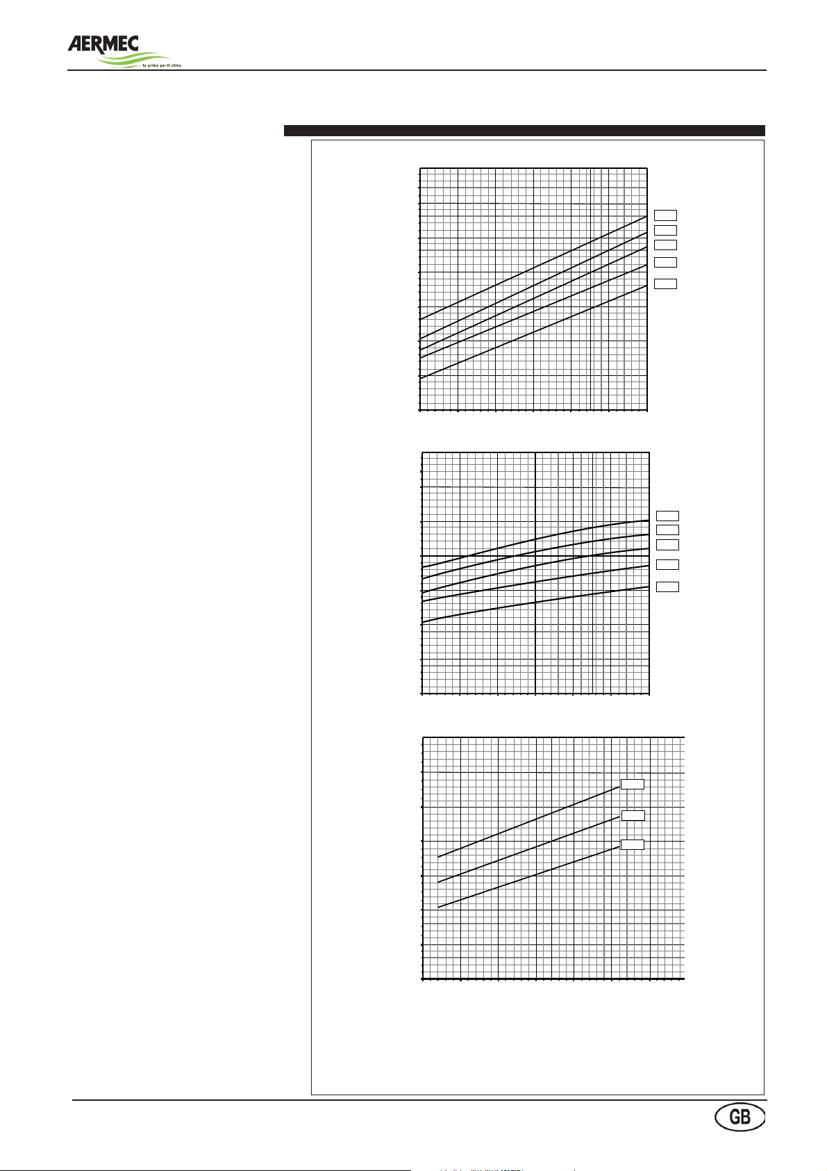
Cooling capacity and input power
The following diagrams make it possible
to obtain the corrective coefficient to be
used for the rooftop units in the cooling
function. Alongside each curve, the
temperature of the outside air it refers
to is reported.
The total cooling capacity, the sensible
cooling capacity and the electrical
input power in conditions other than
the nominal ones are obtained by
multiplying the nominal values in the
technical data table for the respective
correction coefficients (Cft, Cfs e Cpa).
Example: if RTE 240F on the technical
data sheet capacities with nominal air
flow at 27°C and 50% R.H.: tot. refrig.
cap. of 66.0 kW and sens. refrig. cap.
45.2 kW with outside air 35°C;
Then at 24°C and 50% H.R. will supply
respectively : 66.0x0.92=60.7 kW and
45.2x0.97=43.8 kW.
Cft
Total cooling capacity coefficient
Cfs
#
#
#
#
#
#
#
#
#
#
Te [°C]
Te [°C]
Cpa
Input power coefficient Sensible cooling capacity coefficient
#
#
#
Te [°C]
Tav.01
Key
Cft Coefficient Total cooling capacity
Cfs Sensible cooling capacity coefficient
Cpa Input power coefficient
Manual selection, installation and maintenance
Temperature of the air to be treated b.s. 50% R.H. [°C]
Te External air temperature °C
b.s. Dry bulb
R.H. Relative Humidity
21

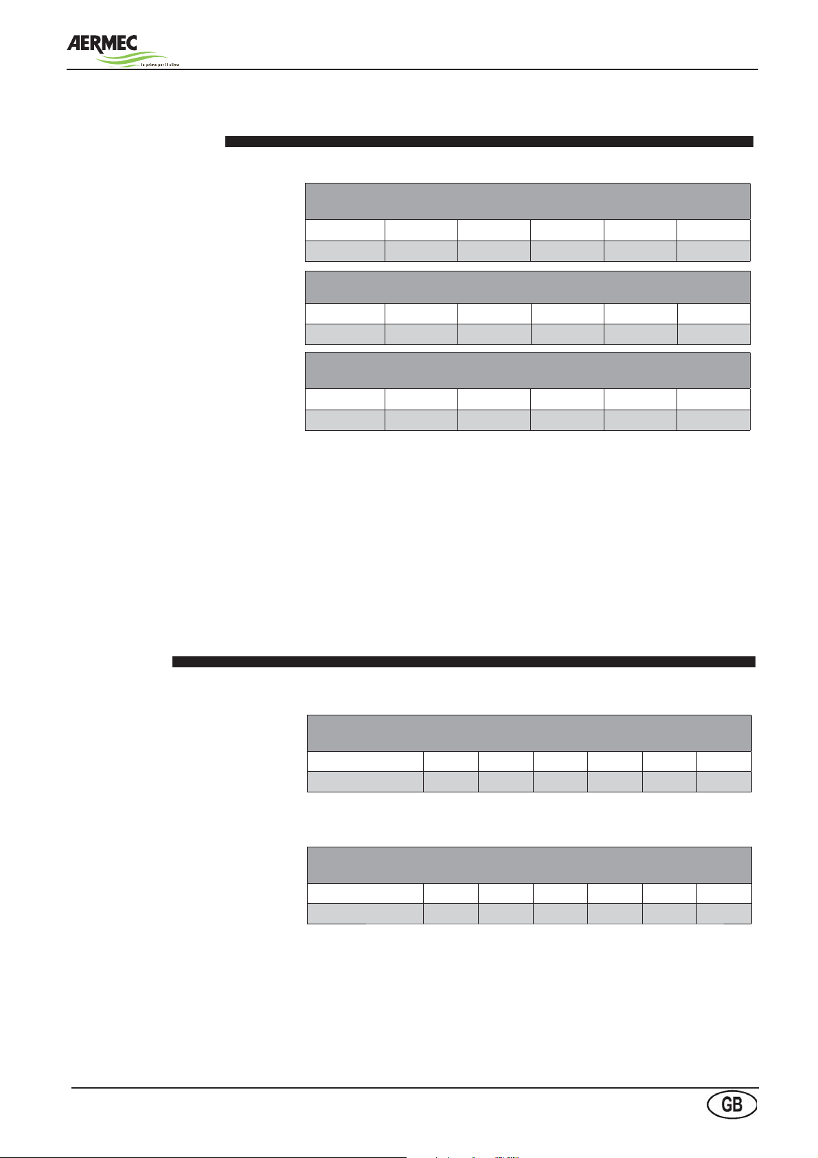
The following diagrams give the
corrective coefficients to be used for the
rooftop units operating in heat pump
mode. Each curve refers to a specific
room temperature (16-20-24°C). The
x-axis shows the dry temperature of
the external air with variable relative
humidity, according to the data shown
in the table below.
The performances are given net of the
defrosting cycles.
The corrective coefficients (Cpt, Cpa)
allow to calculate the heating capacity
and the electrical input power at
conditions other than the nominal ones.
Roof-top units - RTE series-
Heating capacity and input power
Cpt
Heating capacity coefficient
#
#
#
T [°C]
Cpa
Input power coefficient
KEY
Cpt Heating capacity coefficient
Cpa Input power coefficient
d.b. Dry bulb
T [°C] Dry bulb temperature of the handled air.
External air d.b. [°C]
#
#
#
T [°C]
The x-axes show a temperature which refers to the following humidity conditions:
Temp. in x-axis °C -8 -6 -4 -2 0 246810121416
Dry bulb temp °C-8-6-4-20246810121416
Rel. Humid. %90908580757570707065656565
Manual selection, installation and maintenance
22
Roof-top units - RTE series-
Corrective coefficients for different flow rates
The data given by the diagrams at pg.
21-22 refer to nominal air flowrates
(Wn).
For different flowrates (W) please apply
the corrective coefficients shown in the
tables on the right.
Correction coefficients for flow rates other than the rated flow rates by total
cooling capacity
W/Wn 0,8 0,9 1 1,1 1,2
Cft 0,974 0,987 1 1,014 1,027
Correction coefficients for flow rates other than the rated flow rates and for sensitive
cooling capacity
W/Wn 0,8 0,9 1 1,1 1,2
Cfs 0,905 0.953 1 1.048 1.095
Correction coefficients for flow rates other than the rated flow rates for heating
capacity
W/Wn 0,8 0,9 1 1,1 1,2
Cpt 0,974 0,987 1 1,014 1,027
KEY
Cft Coefficient Total cooling capacity
Cfs Sensible cooling capacity coefficient
Cpt Heating capacity coefficient
The input power does not vary greatly with the variation in the flow rate of the air
to be treated
Total capacities for different relative humidities
The table gives the corrective
coefficients to calculate the TOTAL
COOLING CAPACITY for different
relative humidities, dry bulb
temperature unchanged.
The table gives the corrective
coefficients to calculate the SENSIBLE
COOLING CAPACITY for different
relative humidities, dry bulb
temperature unchanged
Correction coefficients for total refrigeration capacities as the relative humidity
changes
R.H. % 30 40 50 60 70
Coefficient 0.89 0.94 1 1.06 1.12
Correction coefficients for sensible refrigeration capacities as the relative
humidity changes
R.H. % 30 40 50 60 70
Coefficient 1.23 1.11 1 0.89 0.79
Example: if RTE 240F on the technical data sheet supplies at 27°C and 50% R.H.:
tot. refrig. cap. of 66.0 kW and sens. cooling cap. 45.2 kW with outside air 35°C;
Then at 27°C and 70% R. H. supplies respectively: 66.0x1.12=73.9 kW
and 45.2x0.79=35.7 kW.
Manual selection, installation and maintenance
23

0,9
1,0
1,1
1,2
1,3
1,4
0% 5% 10% 15% 20% 25% 30% 35% 40%
FcGDpC
FcGQC
Performance tables for water heating coils
The RTE units may be supplied with a
two-row hot water coil (accessory)
provided with modulating three-way
valve (actuator included).
The first diagram shows the corrective
coefficients to be applied to the nominal
performances of the hot water coil given
on pg. 13.
Example :
Calculate the performances of the hot
water coil installed on a RTE 240 at the
following design conditions:
· Heating water inlet temperature: 70 °C;
· Room temperature: 22 °C;
· Water thermal drop
The coil heating capacity, with air at 20°C
and water 80/70°C, is 140 kW according
with the technical data sheet at pg. 13.
The temperature difference between
the water inlet and the air is DAW=7022=48°C.
The diagram gives the corrective
coefficient Cfpt=0.63. Hence the coil
heating capacity at the given condition is
140x0.63=88.2 kW.
T20=20 °C.
CfPT
key• key
CfPT Heating
capacity corrective
coefficient
DAW Temperature
difference between
water inlet - air inlet
[°C]
∆ t Water thermal
drop [°C]
[kPa]
351
Roof-top units - RTE series-
AW
$4#
$4#
$4#
K
Water coil pressure
drops
Fig.04 shows the heating coil water
pressure drops.
The pressure drops due to the three-way
valves are included.
Corrective coefficients
for pressure drop and
flowrate with glycoled
water
FcGDpC = Pressure drop corrective
coefficient
FcGQC = Flowrate corrective
coefficient
The water flowrate and pressure drop
corrective coefficients have to be
applied directly to the data for normal
water.
Water pressure drop
Water flow rate [l/h]
Percentage of ethylene glycole
Percentuale di glicole etilenico
fig.04
Manual selection, installation and maintenance
24

Roof-top units - RTE series-
Technical data generator Gxxx
Gxxx Model G72 G92 G150
RTE
Matching with sizes RTE
Combination thermal modu-
les
Temperature rise (at nominal air flow and maximum
heat output)
Thermal Module 072 092 150
Nominal air flow kW 22 78 30 98 44 155
Efficiency % 105 93,8 105 95,3 105,2 93,5
Nominal thermal power kW 23,1 73,2 31,5 93,4 46,3 145
Condensate produced l/h 2,2 2,6 3,9
NOx mg/kWh 35 37 43
Gas connection diameter UNI ISO 7/1 - 1” M UNI ISO 7/1 - 1” M UNI ISO 7/1 - 1” M
diameter tube suction / discharge mm 100 / 100 100 / 100 350 / 350
Available pressure exhaust fumes Pa 120 120 100
Minimum working temperature °C -15 -15 -15
Power supply V / Hz 230 / 50 230 / 50 230 / 50
Category II 2H 3B/P
G20 natural gas supply pressure mbar 20 (min. 17; max. 25)
G20 natural gas consumption (15 ° C - 1013mbar)
Carbon dioxide gas supply pressure G30CO2 G20
Supply Pressure G30 mbar 37
Consumption G30 (15 ° C - 1013mbar)
Carbon dioxide CO2 G30 % 9,5 +/- 0,3
Supply Pressure G31 mbar 37
Consumption G31 (15 ° C - 1013mbar)
Carbon dioxide CO2 G31 % 9,5 +/- 0,3
RTE240 RTE240 RTE260 RTE300 RTE350 RTE400 RTE260 RTE300 RTE350 RTE400
model
n° x
model
1x72 1x92 1x92 1x92 1x92 1x92 1x150 1x150 1x150 1x150
°C
20 25,5 17,9 15,2 13,8 13,2 27,7 23,5 21,4 20,5
min. max. min. max. min. max.
m3/h 2,33 - 8,25 3,18 - 10,38 4,50 - 15,80
% 8,7 +/- 0,2
m3/h 1,42 - 5,02 1,93 - 6,31 2,83 - 9,97
m3/h 1,40 - 4,95 1,88 - 6,14 2,76 - 9,71
Manual selection, installation and maintenance
25

Roof-top units - RTE series-
List of pressure equipment - Directive PED 97/23 CE
The table alongside shows the list of pressure equipment
and form mounted on the roof-top RTL, according to
Directive 97/23 CE PED module A1.
Refrigerant circuits
RTE 240 F - 400 F refrigerating circuit
EB
AP
PA
COMPONENT MODULE
Compressor D1
Coil A
Three way valve esclusa (art. 3.3)
Liquid receiver D1
High pressure switch B+D
Safety valve high pressure side B+D
Safety valve low pressure side B+D
IB
SR
MV
SV
PC
P
B
AP
TV
L
I
SR
NOTE: This scheme refers to only one of the two circuits. Scketched elements are optional.
CP compressor FI filter drier
VS high pressure safety valve 30 bar VO solenoid valve (optional)
AP high pressure switch (27 bar) IL liquid and humidity indicator
PA pressure transducer VT thermostatic expansion valve
RS ball valve (optional) VM centrifugal fan
EV axial fan BI internal coil
BE external coil BP low pressure switch (it stops the compressor at 2 bar and starts it at 2,3 bar)
IF
OV
Manual selection, installation and maintenance
26

RTE 240 H - 400 H refrigerating circuit
EV
EB
Roof-top units - RTE series-
CIV
P
A
B
I
MV
PA
SV
PC
AP
UV
UV
PBSV
TV
I
L
P
Z
V
O
LR
FI
V
U
NOTE: This scheme refers to only one of the two circuits.
CP compressor VO solenoid valve
VS high pressure safety valve 30 bar PZ temperature probe pit
AP high pressure switch (27 bar) IL liquid and humidity indicator
PA pressure transducer VT thermostatic expansion valve
VIC refrigerant reversing valve VSBP by pass solenoid valve
EV axial fan VM centrifugal fan
BE external coil BI internal coil
FI filter drier RL liquid receiver
VU one way valve
U
V
Manual selection, installation and maintenance
27

Base versions
Base versions
Single section rooftop
• front exhaust
• downwards supply
• filters G4
(optional heating coil)
(fig.1)
Standard air flow
SMP
Single section rooftop
• two-ways mixing box, rear exhaust
intake (actuator as optional)
• filters G4
(optional heating coil)
FT7
Single section rooftop
• prefilter G3
• bag filters F7
(heating coil as optional)
SM2
Single section rooftop
• two-ways mi x i n g bo x , s i d e or
bottom exhaust intake (actuators as
optional)
• filters G4
(optional heating coil)
SM2-FT7
Single section rooftop
• two-ways mixing box with side,
bo ttom or front exhaust i ntake
(actuators as optional)
• prefilter G3
• bag filters F7
(heating coil as optional)
(fig.2)
(fig.3)
(fig.4)
(fig.5)
Single section rooftop
• front exhaust
• downwards supply
• filters G4
(optional heating coil)
Roof-top units - RTE series-
Dimensions
SMP
Single section rooftop
• two-ways mixing box, rear exhaust
intake (actuator as optional)
• filters G4
(optional heating coil)
FT7
Single section rooftop
• prefilter G3
• bag filters F7
(heating coil as optional)
Standard air flow
3930
3930
3290
(fig.1)
(fig.2)
(fig.3)
SM2
Single section rooftop
• two-ways mixing box, side or
bottom exhaust intake (actuators as
optional)
• filters G4
(optional heating coil)
SM2-FT7
Single section rooftop
• two-ways mixing box with side,
bottom or front exhaust intake
(actuators as optional)
• prefilter G3
• bag filters F7
(heating coil as optional)
Manual selection, installation and maintenance
28
4500
4500
(fig.4)
(fig.5)

G72 - G92 - G150
G72 - G92 - G150
Single section rooftop
• prefilter G3
• hot air condensation type generator with
72 or 92 kW heating capacity according
to the selected rooftop version. The
generator is installed in a module with
sandwich panels with mineral wool
insulation (density 100 kg/m
3
)
SM3
Rooftop
• three-way mixing box with:
exhaust fan with variable pitch
pulley
- standard rain hoods
- modulating actuators for all the
da m pers (modulat ing s pring
return actu ators for external
damper as optional).
Exhaust
air intake
Optional exhaust air
intake
G72 - SMP / G92 - SMP / G150 - SMP
G72 - F7 / G92 - FT7 / G150 - FT7
SM3 - FT7
(fig.6)
(fig.7)
(fig.8)
(fig.9)
(fig.10)
Single section rooftop
• prefilter G3
• hot air condensation type generator with
72 or 92 kW heating capacity according
to the selected rooftop version. The
generator is installed in a module with
sandwich panels with mineral wool
insulation (density 100 kg/m
SM3
Rooftop
• three-way mixing box with:
-
exhaust fan with variable pitch
pulley
- standard rain hoods
- modulating actuators for all the
dampers (modulating spring
return actuators for external
damper as optional).
3
)
Exhaust
air intake
4985
5310
Optional exhaust air
intake
Roof-top units - RTE series-
(fig.6)
(fig.7)
G72 - SMP / G92 - SMP / G150 - SMP
G72 - F7 / G92 - FT7 / G150 - FT7
5625
5625
(fig.8)
(fig.9)
SM3 - FT7
Manual selection, installation and maintenance
29
5950
(fig.10)

SM2 - G72 / SM2 - G92 / SM2 - G150
SM2 - G72 / SM2 - G92 / SM2 - G150
SM2 - G72 - FT7
SM2 - G92 - FT7
REC
REC - FT7
(fig.11)
(fig.12)
(fig.13)
(fig.14)
SM2 - G72 - FT7
SM2 - G92 - FT7
SM2 - G150 - FT7
SM2 - G72 - FT7
SM2 - G72 - FT7
SM2 - G92 - FT7
SM2 - G92 - FT7
SM2 - G150 - FT7
6280
Roof-top units - RTE series-
(fig.11)
REC
Rooftop:
• Heat recovery unit provided with :
- exhaust fan with variable pitch
pulley
- panel filters G4 for exhaust air
- panel filters G4 for fresh air
- modulating actuators for all the
dampers (modulating spring
return actuators for external
dampers as optinal).
- double filter differential pressure
switch as optional
REC - FT7
6280
7080
(fig.12)
(fig.13)
Manual selection, installation and maintenance
30
7080
(fig.14)

(fig.15)
(fig.16)
(fig.17)
(fig.18)
SM3 - G72
SM3 - G72
SM3 - G92
SM3 - G150
SM3 - G72 - FT7
SM3 - G92 - FT7
SM3 - G150 - FT7
REC - G72
REC - G92
REC - G150
REC - G72 - FT7
REC - G92 - FT7
REC - G150 - FT7
SM3 - G92
SM3 - G150
SM3 - G72 - FT7
SM3 - G92 - FT7
SM3 - G150 - FT7
7005
Roof-top units - RTE series-
(fig.15)
REC - G72
REC - G92
REC - G150
REC - G72 - FT7
REC - G92 - FT7
REC - G150 - FT7
8125
7645
(fig.16)
(fig.17)
Manual selection, installation and maintenance
31
8765
(fig.18)

Nominal dimensions
RTE 240-260-300-350 - 400 standard base version
Roof-top units - RTE series-
2172
2162
3291
3282
2246
1830
1730
Refrigerant charge
R410A REFRIGERANT CHARGE -ONLY COOLING VERSION
Model 240 F 260 F 300 F 350 F 400 F
Std version [kg]
High temperature version [kg]
Low noise version [kg]
R410A REFRIGERANT CHARGE - HEAT PUMP VERSION
Model 240 H 260 H 300 H 350 H 400 H
Std version [kg]
High temperature version [kg]
Low noise version [kg]
Manual selection, installation and maintenance
Contact the technical department AERMEC S.p.A.
Contact the technical department AERMEC S.p.A.
32

Roof-top units - RTE series-
Weights
WEIGHTS - ONLY COOLING VERSION
Model 240 F 260 F 300 F 350 F 400 F
Std version [kg] 3500 1420 1460 1610 1695
SMP [kg] 1460 1590 1630 1770 1855
FT7 [kg] 1532 1660 1700 1840 1925
SM2 [kg] 1600 1640 1770 1910 1995
SM2 - FT7 [kg] 1630 1670 1800 1940 2025
Weight addition for high temperature/low noise versions
[kg] + 50 + 50 + 50 n.d. n.d.
WEIGHTS - HEAT PUMP VERSION
Model 240 H 260 H 300 H 350 H 400 H
Std version [kg] 1350 1380 1550 1690 1775
SMP [kg] 1500 1540 1720 1860 1945
FT7 [kg] 1550 1560 1760 1900 1985
SM2 [kg] 1570 1580 1950 2260 2175
SM2 - FT7 [kg] 1670 1680 2060 2200 2285
Weight addition for high temperature/low noise versions
WEIGHTS VALID FOR BOTH VERSIONS ONLY COOLIG AND HEAT PUMP
Model 240 F/H 260 F/H 300 F/H 350 F/H 400 F/H
Two rows water coil [kg] 55 55 55 55 55
Heat generator 72 kW [kg] 610 n.d. n.d. n.d. n.d.
Heat generator 92 kW [kg] 650 650 650 650 650
Heat generator 150 kW [kg] n.d. 700 700 700 700
Heat generator 72 kW + two ways mixing box rear exhaust
and/or bag filters
Heat generator 92 kW + two ways mixing box rear exhaust
and/or bag filters
Heat generator 150 kW + two ways mixing box rear exhaust
and/or bag filters
Heat generator 72 kW + two ways mixing box side exhaust
and/or bag filters
Heat generator 92 kW + two ways mixing box side exhaust
and/or bag filters
Heat generator 150 kW + two ways mixing box side exhaust
and/or bag filters
Three way mixing box [kg] 560 570 580 600 600
Heat recovery unit [kg] 890 900 910 940 940
[kg] 50 50 50 n.d. n.d.
[kg] 840 n.d. n.d. n.d. n.d.
[kg] 860 860 860 860 860
[kg] n.d. 900 900 900 900
[kg] 1040 n.d. n.d. n.d. n.d.
[kg] 1060 1060 1060 1060 1060
[kg] n.d. 1100 1100 1100 1100
Manual selection, installation and maintenance
33

Configurations
RTE 240-260-300-350 with two-ways mixing box SM2
The ROOFTOP units with two-ways mixing
box are available in the following different
configurations:
T1 - RIGHT SIDE ROOM AIR INTAKE
The damper for the room air intake is on the
right side of the unit while the fresh air damper
is on the back of the unit.
T2 - LEFT SIDE ROOM AIR INTAKE
The damper for the room air intake is on the
VERSIONS MIXING
VERSIONI CAMERA DI MISCELA A 2
CHAMBER AT 2 DAMPERS
SERRANDE TIPO SM2
SM2
left side of the unit while the fresh air damper is
on the back of the unit.
T3 - REAR ROOM AIR INTAKE
The dampers for the room air intake and the
fresh air intake are both on the back of the unit.
This version is required only when the units is
provided also with FT7 bag filters; if there are
no bag filters, select the two-ways mixing box
'SMP' type.
T4 - BOTTOM ROOM AIR INTAKE
The damper for the room air intake is at the base
Roof-top units - RTE series-
of the unit while the fresh air intake is on the
back of the unit
5 - AMBIENT AIR INLET SIDE RIGHT
The air intake damper the environment to conditions and post to the right of following the
flow
air, while the air damper External renewal is to
the left unit.
T6 - SUCTION AMBIENT AIR LEFT SIDE
The damper air intake from the environment to conditions and to the left of the
unit following the flow of air, while the
outside air damper for renewal shall be
placed to the right of the unit.
.
SM2 T1
Presa aria di rinnovo
Fresh air intake
con serranda interna
with internal
damper
SM2 T3
Note: recommended
N.B.: consigliato solo
only with filters F7
con filtri F7
Front
recirculation
damper
T4
SM2
Right recirculation
Serranda di ricircolo
destra
damper
Serranda di ricircolo
posteriore
Bottom
recirculation
Serranda di ricircolo
inferiore
damper
Right
Serranda di ricircolo
recirculation
sinistra
damper
SM2 T2
SM2
T6
Manual selection, installation and maintenance
SM2 T5
34

Roof-top units - RTE series-
RTE 240-260-300-350
with three-way mixing
box
STANDARD - REAR INTAKE
The room air intake is from the back of the
unit
.
AI - BOTTOM INTAKE
The exhaust air is intaken from the
bottom of the vertical exhaust section
integrated in the three-way mixing box.
AS - HIGHER ASPIRATION
The exhaust air is intaken from the
higher the vertical exhaust section
integrated in the three-way mixing box.
THREE-WAY MIXING BOX
STANDARD
Damper renewals
with waterproof headphones
Damper
removal
AS - Higher
aspiration
AI
Bottom intake
RTE 240-260-300-350
with heat recovery unit
• Heat recovery unit provided with :
- exhaust fan with variable pitch
pulley
- panel filters G4 for exhaust air
- panel filters G4 for fresh air
- modulating actuators for all the
dampers (modulating spring
return actuators for external
damper as optional).
- double filter differential pressure
switch as optional.
- cross flow heat exchanger sized
for the recovery of up to 100%
flow
HEAT RECOVERY CROSS FLOW REC
HEAT RECOVERY WITH CROSS-FLOW BYPASS REC BP
Manual selection, installation and maintenance
Air return
Damper
renewal
35
Damper
removal
Inspection
coil
Filters renewal
inspection
Inspection fan and filter recovery
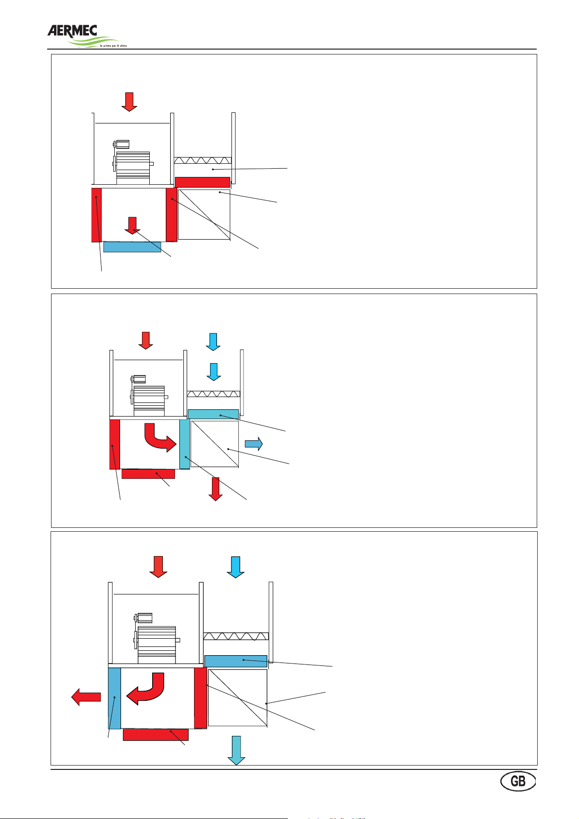
RTE with recuperator
Heating up operation (all fresh air)
EXHAUST AIR
Rinnovo
Espulsione
CHIUSA
pulsione Rec.
Roof-top units - RTE series-
In the heating up modality, the outside exhaust damper and the recuperators exhaust damper are completely closed, while the recirculation
damper is entirely open. All exhaust air flow is recirculated until the
desired room temperature is reached.
FRESH DAMPER
CROSS FLOWS RECUPERATOR
RECIRCULATION DAMPER
ROOM AIR
Total recovery operation
EXHAUST AIR
Espulsione
RECIRCULATION
EXHAUST
DAMPER
DAMPER
FRESH AIR
Rinnovo
pulsione Rec.
RECUPERATORS EXHAUST DAMPER
In the total recovery operation, the outside exhaust damper and
the recirculation damper are completely closed, while the recuperators exhaust damper is entirely open. According to the operation type (winter or summer) the exhaust air exchanges heat with
the fresh air.
It is possible to set a partial recovery operation: the recuperators
exhaust damper reaches the percentage of the set opening while
the remaining air flow crosses through the recirculation damper.
FRESH DAMPER
CROSS FLOWS RECUPERATOR
EXHAUST AIR
RECUPERATORS
EXHAUST DAMPER
Free-cooling operation
EXHAUST AIR FRESH AIR
Rinnovo
EXHAUST
Espulsione
AIR
EXHAUST
DAMPER
RECIRCULATION
DAMPER
Manual selection, installation and maintenance
pulsione Rec.
In this modality, the recuperators exhaust damper and the
recirculation damper are completely closed, while the outside
exhaust damper remains entirely open.
The exhaust air is therefore directly conveyed to outside
without crossing through the heat recuperator. The fresh air is
extracted from outside and introduced in room.
FRESH DAMPER
CROSS FLOWS RECUPERATOR
RECUPERATORS
EXHAUST DAMPER
36

RTE with heat generators G72 - G92 kW
(Here is the image of the version with bag
filters and edge inspection R)
Form of heat from the generator
72 or 92 kW supplied with:
- Combustion chamber condensing heat exchanger tube boilers;
- Modulating gas burner premixed
methane;
- Insulated stainless steel flue terminal anti reflux provided in support;
- Conversion kit to LPG;
- Electronic controller and safety
thermostats.
Air flow
Roof-top units - RTE series-
Survey electrical
connection box
Burner
and boiler
inspection
Gas Line In
Condensate drain boiler
Inspection filters
RTE with heat generators G150 kW
(In this position is displayed the version
with flat filters and left inspection)
Form 150-kW generator of heat supplied with:
- Combustion chamber condensing
heat exchanger tube boilers;
- Modulating gas burner premixed
methane;
- Insulated stainless steel flue terminal
anti reflux provided in support;
- Conversion kit to LPG;
- Electronic controller and safety thermostats.
Air flow
Inspection filters
Burner and boiler
inspection
Manual selection, installation and maintenance
Condensate drain boiler
37
Gas Line In

Roof-top units - RTE series-
PR2 Remote panel (accessory)
The graphic display is an electronic
device that allows for the complete
management of the graphics through
the display of icons (defined at
the level of software application
development) and the management
of two dimension international fonts:
5x7 e 11x15 pixel. The application
software is only resident on the card.
The terminal does not need any
additional software in the usage phase.
In addition, the terminal offers a wide
range of operating temperature and
in the wall built-in version, the front
guarantees a high degree of electrical
protection (IP65).
30,4
67
18
156
125,5
Manual selection, installation and maintenance
38

Roof-top units - RTE series-
Packaging
The RTE series units are usually
supplied without packaging with the
exception of high-efficiency filtering
cells and assembly accessories, which
are supplied in cardboard boxes and
have to be installed by the customer.
Upon request, the units can be supplied
packaged with polyethylene fim on
pallets + polyethylene film, in a cage or
in a crate.
Handling
Before moving the unit make sure that it
has not been damaged during transport
and make sure that the equipment
to be used for lifting and positioning
is adequate in terms of capacity and
complies with security regulations
currently in force.
Particular attention must be paid to all the
loading, unloading and lifting operations
so as to avoid dangerous situations for
people and damage to the structure and
operational parts of the machine.
The holes in the base to be used for
lifting are indicated with yellow stickers
showing a black arrow.
The iron poles, which must be suitably
sized, must protrude from the base unit
for a sufficient length so that the lifting
straps can be tightened upwards without
encountering any interference.
Make sure that the belts have been
approved for supporting the weight of the
unit, make sure they are properly fixed to
the upper frame and to the lifting poles.
The safety closures must guarantee that the
belts do not come out of their seats.
The hooking point of the lifting frame must
be on the vertical of the centre of gravity.
The positioning must be done using two
transpallet, one for each side of the section,
preferably acting on the longer sides.
Alternatively the positioning can be done
by sliding the centre on the tubes that act as
rollers.
During lifting operations we recommend to
mount the shock absorbers (VT), fixing the
holes on the base according to the assembly
accompanying the accessories (VT).
Under no circumstance should anybody or
anything stay, even for short periods, under the
unit.
The machines in the RTE series must be
installed externally in an area suitable
for this purpose, which has the required
technical spaces. This is essential to
allow ordinary and extraordinary
maintenance and for functioning reasons
3.000
Installing and using the unit
as the device must gather air from
the outside along the perimeter sides
and expel it upwards. For the proper
functioning of the unit, this must be
installed on a perfectly flat surface. Make
sure that the resting surface is able to
bear the weight of the machine.
Positioning
If the unit is situated in particularly windy
environments it is necessary to install
a wind break barrier to avoid unstable
operation of the DCPR device.
Minimum space
requirements
CAUTION:
The equipment must be installed in such
a way as to make maintenance and/or
repair operations possible, see fig.05.
The equipment warranty does not cover
costs due to motor ladders, scaffolding
or other raising systems made necessary
to carry out the operations covered by
the guarantee.
Before commissioning
the unit
Before starting up the unit you should
check that :
– the electrical connections have been
made properly;
– the line voltage is within the admitted
tolerance limits (±10% of the rated value);
WARNING:
At least twenty-four hours before the
unit start-up (or at the end of each
period of prolonged stop) power up
3.000
the compressors crankcase heaters
to evaporate any refrigerant in
the oil. Without this precaution the
compressors could be seriously
damaged and the warranty could cease
to be valid.
Unit start-up
Commissioning the units must be
previously agreed on the basis of the
timing for the realisation of the installation
Before the intervention of AERMEC
After Sales Service all the works
(aeraulic, hydraulic and electrical
connections, loading and blowing out
of air from the system) will have to be
completed.
For the setting of all the operating
parameters and for detailed information
regarding the operation of the machine
and check list, refer to the user's
manual.
System charge/discharge
During the winter period, only in the
case of water coils, if the system is left
still, the water in the heat exchanger
might freeze and damage the heat
exchanger irreparably.
To avoid the risk of freezing, there are
three possible solutions:
1) The complete drainage of the water
from the heat exchanger at the end
of the season and refilling at the
beginning of the next season.
2) Operation with glycol water with
a glycole percentage chosen on
the basis of the minimum external
temperature expected. In this case,
due account must be taken of the
heating coil performance and pump
scaling.
3) Keeping the temperate of the water above
5°C.
.
fig. 05
1.200500
800 800
Manual selection, installation and maintenance
39

Roof-top units - RTE series-
Norms covering the use
of R410A gas
Rooftop units functioning with refrigerating
R410A gas require particular attention at
the assembly stage and during maintenance
so as to keep them from malfunctioning.
It is therefore necessary:
- To avoid refilling with oil different
from the one specified which is
already pre-charge in the compressor.
- If there are gas leaks implying that
the Rooftop units are even partially
empty, do not refill the refrigerant
partly but completely drain the
machine and after evacuating it
completely fill it again with the
amount required.
- In the event of replacement of one of
the refrigerating circuit parts, do not
leave the circuit open for more than
15 minutes.
- In particular, in the case of
substitution of the compressor,
complete the installation within
the above mentioned times after
removing the rubber caps.
- Do not power up the compressor if it
is empty; do not compress air inside
the compressor.
- If you use R410A gas tanks, please pay
attention to the maximum number of
withdrawals you can make in order to
ensure the correct ratio of the components
in the R410A gas mixture.
Hydraulic connections
Condensate drain pain
The condensate drain pan has a
threaded drain pipe 1” G UNI 338.
The drainage system should feature an
adequately sized siphon to:
• allow the free drainage of the
condensate;
• prevent the undesired inlet of air in
the vacuum systems;
• prevent the undesired air leakage
from pressure systems;
• prevent bad smells or insects from
infiltrating.
Here below you will find rules to adopt
for the dimensioning and creation of
syphons in the case of pressure and
vacuum tanks fig.06.
Negative pressure:
H1 = 2P
H2= H1 / 2
Positive pressure:
H1 = 2P
H2= H1 / 2
neg.
P
H3
H1
H2
pos.
P
G072, G92, G150 gas
supply system
For this system, use CE-approved and
certified components only.
G072, G105, G150 modules are supplied with:
- a double gas valve;
- a gas filter and stabiliser;
already installed.
All components are assembled into the
burner housing.
To complete installation in compliance
with the law, the following components
have to be installed:
where P is the internal pressure expressed
as mm of a water column (approx. 1 mm
= 9.81 Pa), This pressure is indicated in the
relevant label near the condensate drainage
point.
The syphon must be equipped
with a plug for the cleaning at the
bottom or must anyway allow for fast
dismantling for cleaning purposes.
H3
H1
H2
fig.06
- vibration damping joint;
- gas cock.
We recommend installing a gas filter
with a high flow rate and no pressure stabiliser. In fact, the standard filter installed
before the gas valve has a limited surface.
To assure efficient maintenance, use a
gasket and a swivel joint to connect the
G072, G92, G150 module.
Do not directly use threaded joints on
gas fitting.
The law allows a maximum pressure
of 40 mbar inside the building or thermal plant. Higher pressure values shall
be reduced before the room where the
G072, G105, G150 module is installed.
Manual selection, installation and maintenance
40

KEY
Main burner gas solenoid valve
1
2 Pilot burner gas solenoid valve valve
3 Pressure stabiliser
4 Safety solenoid valve
5 Gas filter (small section)
6 Vibration damping joint
7 Gas filter (large section)
8 Gas cock
included in G072,
G105,G150 module supply
1 2 3 4 5 6 7 8
only for G 150
Roof-top units - RTE series-
to be installed
by the installer
fig.07
Connection aeraulic
For the installation of the ducts it is
recommended to:
• install adequate brackets to support
the ducts;
• connect the supply and exhaust vents
to the ducts by means of antivibration
canvases. The antivibration canvas
has to be connected to the unit
screwing it to the flange or damper,
if present. If the flange or the damper
are not present, the antivibration
canvas has to be screwed to the frame
of the unit using drive screws;
• put in place an electrical earthing
cable that acts as a bridge over the
shock absorber joint to guarantee
electrical equipotentiality between
the duct and the unit;
• foresee, before bends, branches,
curves, angles etc., the supply duct
with a straight stretch at least 2.5
times longer than the smaller side of
the duct (A) to avoid a fall off in the
performance of the fan;
• avoid the ducts from having stretch
inclinations that diverge more 7°C.
The progress of the first curve must
conform
it to the flange or damper, if present.
with the orientation of the fan.
max 25mm
Manual selection, installation and maintenance
MAX 7°
A
MIN 2.5 A
41

The figure illustrates how joinign two
sections. It is referred to a tree way
mixing box, but its the same for the
recovery unit or the or the condensation heat generator.
Roof-top units - RTE series-
Joining RTE sections
Place the sections to unite:
the rubber seal that ensures
the seal is fit along the entire
perimeter of the air passage
of the section upstream.
Be aware to pass through the
electrical connections. Use
the brakets (placed in the box
inside the compressor cabinet)
to complete the assembly. The
gap between the two sections
should be about 10 mm .
Apply the governing (mounted
temporarily on the roof of the
section upstream) and plates provided in support (in the compressor compartment) at the base.
Before placing the Tegolino
union sections, apply silicone sealant along the entire
length at the bottom where
it supports the roofs of the
two units.
MIN 2.5 A
Manual selection, installation and maintenance
42

Improper use
Roof-top units - RTE series-
The equipment is designed and
constructed to guarantee the maximum
security in the immediate proximity as
well as to resist atmospheric agents.
The fans are protected from undesired
intrusion of bodies by protection grilles.
The accidental opening of the electrical
panel with the machine in operation is
prevented by the door lock sectioning
device.
Avoid laying tools or heavy objects on
the side heat exchanger coils to avoid
ruining the fin pack.
Do not introduce objects or allow
them to fall through the grilles of
the fan motors.
Do not rest on the heat exchanger
coils: sharp surfaces.
Important information
The machine must not exceed the
pressure and temperature limits
indicated in the table shown in the
"Operating limits” section.
Correct functioning is not guaranteed
after a fire; before starting up the
machine again, contact an authorised
after sales centre.
The machine is provided with safety
valves that in the case of excessive
pressure may discharge hot gases into
the atmosphere.
Wind, earthquakes and other natural
phenomena of exceptional intensity are
not taken into consideration.
If the unit is used in aggressive
Electrical wiring
atmosphere or with aggressive water
please consult the head office.
Following extraordinary maintenance
carried out on refrigeration circuits,
with the replacement of components,
carry out the following operations
before starting the machine again:
1. Pay the greatest attention when
restoring the refrigerating load
indicated on the machine nameplate;
2. Open all the taps on the refrigerating
circuit;
3. Correctly connect the electrical power
and the grounding;
4. Check the plumbing connections;
5. Check that the condenser coils are not
dirty or clogged;
6. Check the proper rotation of the fans;
The unit is completely wired in the
factory and to be set in motion it
needs to be powered electrically in
accordance with the information on
the nameplate, intercepted with on-line
protection devices.
It is the responsibility of the installation
engineer to dimension the power line
adequately in accordance with the
length, type of cable, input power and
current of the unit and the physical
deployment.
All the electrical connections must
correspond with the regulations
currently in force at the moment of
installation.
WARNING:
For installation requirements, please
refer to the wiring diagram supplied
with the unit.
CAUTION:
Check that all power cables are
correctly secured to the terminals
when switched on for the first time and
after 30 days of use. Then check the
tightening of all the power terminals
twice a year. Loose terminals could
cause the cables and components to
overheat.
NOTE:
Input cuttent ivalues n the table are
referred to the standard unit. The choice
of some accessories could change this
Size 240 260 300 350
Max. compress. absorption
Delivery fan [A] 8,1 10,9 14,4 18,3
Condensation fan (tot.) [A] 9,6 9,6 9,6 10,4
Return fan (optional)
Size 240 260 300 350
SECT. A [mm2]35355070
SECT PE [mm2]25252535
IL [mm2] 100 100 125 160
Cross sections recommended for a maximum length of 50m. The
cross section of the wires and the scaling of the line cutouts are purely
approximate.
Legend:
Cross sect. A = Power line
Cross sect. PE = Ground line
IL = Differential magnetothermal switch
AC23A CEI EN 60947
value. For the real input current of the
unit, please refer to the electrical diagram provided with the unit.
[kW] 12x2 15x2 18x2 18+24
[A] 20x2 26x2 30x2 30+39
[A] 4,8 6,5 10,9 14,4
TAV.3
Manual selection, installation and maintenance
43

Security
Roof-top units - RTE series-
The machine has been designed so
as to reduce to a minimum the risks
for the safety of those persons interacting
with it. During the design phase, it was not
technically possible to
completely eliminate
the risk causes. Therefore it is imperative to
refer to the following instructions.
Access to the unit
Access to the unit once it has been installed
must only be permitted to qualifi ed
operators and technicians. The operator
is a person who has been authorized by
the owner of the machine to carry out
operations on the machine (in accordance
with that indicated in the present manual).
The technician is a person authorized by
AERMEC or subordinate under their own
responsibility by a AERMEC distributor,
to carry out operations on the machine.
The owner of the machine is the legal
representative of the company, entity or
individual owner of the system in which the
AERMEC machine is installed.
These persons are responsible for the
observance of all safety standards indicated
in the present manual and the existing. law.
In the event that access by unauthorized
persons to the machine cannot be prevented
due to the nature of the location in which it
is installed, a cordoned area must be defi ned
around the machine and at least 1.5 meters
from the external surface, inside of
which only operators and technicians are
permitted.
Residual risks
The installation, start-up, shutdown and
maintenance of the machine must be carried
out in accordance with that stipulated in the
technical documentation of the product and
in such a manner that no hazardous
situations are generated.
CONSIDERED PART RESIDUAL RISK METHOD PRECAUTIONS
Heat exchange coil small cuts contact
Fans grille and fan injuries
Insert sharp objects through the
grille while fan is operating
avoid contact with eyes, use
protective gloves
Insert any objects inside fans grille and not put objects on grilles
Inside the unit: compressor
and supply tube severe burns contact
Inside the unit: metal parts
and electrical cables
Outside the unit: area
around the unit
intoxication, electrocution,
severe burns
intoxication, severe burns
insulation defect of the power
supply cables upstream of the
unit’s electric panel; metal parts
under voltage
fire due to short circuit or overheating of the power supply line upstream of the unit’s electric panel
Unit maintenance
The ordinary maintenance must be performed by qualified people each month
and consists in simple operations.
WARNING:
During the maintenance phase,
wear proper individual protection
devices (IPD)
Before performing maintenance
and/or cleaning operations on
the unit, make sure the unit is
disconnected from the power
supply and that it can not be turned back on without the know-
ledge of the person performing
maintenance, and that the heat
exchanger coils are not working.
The compressors upper part and
the supply tube are at high temperature: pay particular attention
when working around them.
Pay particular attention when ope-
rating around the fins coils as
fins are particularly sharp.
Not extract the fans protection
grille before having taken away
the voltage to unit; not put
foreign objects through the fans
avoid contact with eyes, use
protective gloves
suitable electrical protection of
the power supply line; maximum
care when earthing the metal
parts
cable section and power supply
line safety system conforming
with existing laws.
protection grille.
After maintenance operations
always close the unit by means
of the specific panels, fixing
them with screws.
The following table illustrates the operations related
to monthly maintenance of
each component, indicating
the control type to carry out.
The month frequency is indicative
and can change according to work
and environmental conditions in
which the roof top unit operates
Manual selection, installation and maintenance
44
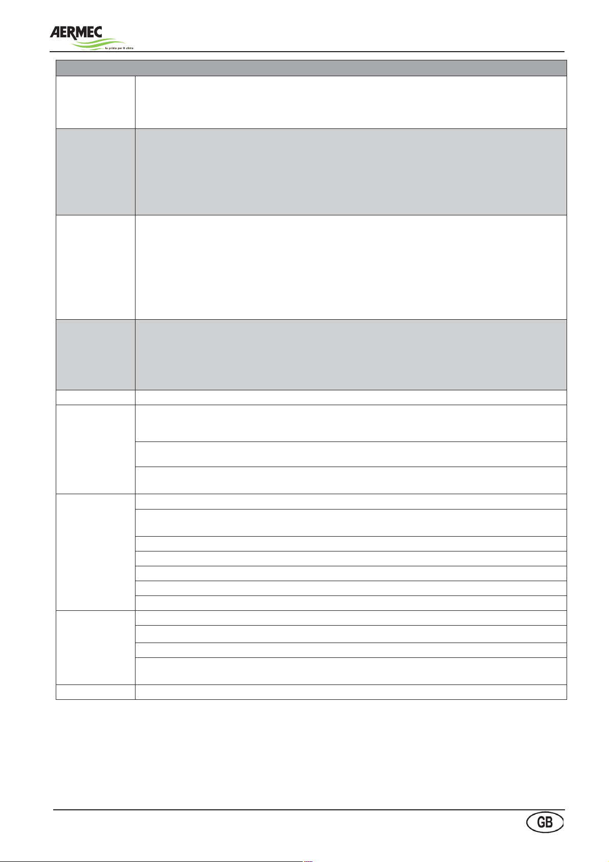
MONTHLY MAINTENANCE PROGRAM
Check the input.
FANS
Check that the
fans motor free
rotate without
abnormal noises.
Make sure that
the bearings
do not heat too
much.
Check that the fans motor free rotate without abnormal noises.
Make sure that the bearings do not heat too much.
Check the fans screws fastening to grille and structure grille.
Verify the condensate coils. To grant a correct heat exchange, coils must be cleaned. It is necessary to provide for the
removal of possible dust collected on the surface due to airflow. Take away paper, leaves etc.. and clean fins with air jet.
To avoid damages to aluminum fins it is necessary that the air jet is direct perpendicularly to coil surface.
The cleaning operation must be performed by particular attention as the coil fin is easy to damage (aluminum from 0,12
mm). If fins are damaged, it is necessary to provide for a suitable arrangement with a specific tool.
Before performing operations on the coils it is necessary to use protective gloves as the possible contact with fins can
cause small cuts.
Check the evaporation and condensate pressures (by a specialized technician).
It is necessary to remove compressors panels and to connect with pressure gauges on the suitable pressure sockets
placed in the cooling circuits.
Check the compressor absorbed current, the supply temperature and the presence of possible noises.
Check the proper refrigerant charge by means of the liquid light.
Verify the correct setting of the expansion valve (overheating 5 ÷ 8°C).
Verify that the oil level indicated in the compressor light is not lower than the minimum.
Check the use of the safety devices (pressure switches).
Roof-top units - RTE series-
Check the fans
screws fastening
to grille and
structure grille.
Check the electric supply on all phases.
Make sure that electrical connections are adequately closed.
Verify that the supply electric cable of the unit does not present alterations which can harm the insulation.
Verify the proper screws blocking which fix the conductors to the electrical components present in the electric panel in
order to grant a proper electrical connection; the same is for the earthing connections.
CONDENSATE • Check the operation of the control device, LEDs and display.
Verify the condensate coils. To grant a correct heat exchange, coils must be cleaned. It is necessary to provide for the
removal of possible dust collected on the surface due to airflow. Take away paper, leaves etc. and clean fins with air jet.
To avoid damages to aluminum fins it is necessary that the air jet is direct perpendicularly to coil surface.
COILS
The cleaning operation must be performed by particular attention as the coil fin is easy to damage (aluminum from 0,12
mm). If fins are damaged, it is necessary to provide for a suitable arrangement with a specific tool.
Before performing operations on the coils it is necessary to use protective gloves as the possible contact
with fins can cause small cuts.
Check the evaporation and condensate pressures (by a specialized technician).
It is necessary to remove compressors panels and to connect with pressure gauges on the suitable pressure
sockets placed in the cooling circuits.
COOLING
CIRCUIT
Check the compressor absorbed current, the supply temperature and the presence of possible noises.
Check the proper refrigerant charge by means of the liquid light.
Verify the correct setting of the expansion valve (overheating 5 ÷ 8°C).
Verify that the oil level indicated in the compressor light is not lower than the minimum.
Check the use of the safety devices (pressure switches).
Check the electric supply on all phases.
Make sure that electrical connections are adequately closed.
ELECTRICAL
CIRCUIT
Verify that the supply electric cable of the unit does not present alterations which can harm the insulation.
Verify the proper screws blocking which fix the conductors to the electrical components present in the
electric panel in order to grant a proper electrical connection; the same is for the earthing connections.
CONTROL Check the operation of the control device, LEDs and display.
Manual selection, installation and maintenance
45

Roof-top units - RTE series-
Diagnosis and fault solving
PROBLEM CAUSE SYMPTOM SOLUTION
1. SUPPLY AIR
TEMPERATURTE
HIGHER THAN
FORESEEN
2. INSUFFICIENT
COOLING
CAPACITY
3. ABNORMAL
NOISE
4.INTERVENTION
OF THE LOW
PRESSURE
SWITCH
1. Heat power too high - The air temperature on supply is
higher than the foreseen value
2. Room temperature too
high
3. Condensers fins clogged See 1.1. - Clean the condensers fins
4. Condensers front surface
obstructed
5. Fan rotates in the opposite
direction
6. No refrigerant in the coo-
ling circuit
1. Insufficient refrigerant
charge
2. Room temperature too
high
1. Vibrations in the ducts - The unit noise is higher than normal - Properly fix the ducts with brackets
2. Loud compressor See 3.1 - Verify and eventually replace
3. Loud expansion valve See 3.1 - Verify. Add refrigerant if necessary.
1. Pressure switch out of use - The compressors stop - Verify and replace the pressure
2. Unit completely empty See 4.1. See 1.6.
3. Refrigerant filter clogged See 4.1. - Verify and replace the filter
4. The expansion valve does
not operate properly
5. Room temperature too low See 4.1. - Install the condensate control kit
See 2.1. - Avoid air recirculation on conden-
See 1.1. - Liberare la superficie frontale del
See 1.1. - Invert the position of two fans
- Low evaporation pressure
- Presence of air bubbles in the
liquid lights
- The cooling circuit operates properly, but with insufficient capacity
See 2.1. - Avoid air recirculation on conden-
See 4.1. - Verify, clean, eventually replace
- Decrease the heat power,
decreasing the flow rate or the air
inlet temperature
ser. Facilitate the fresh air flow.
condensatore ostruita
phases
- Search the refrigerant leakages (by a
specialized technician) and avoid them.
- Realize the recharge (by a
specialized technician)
See 1.6.
ser. Facilitate the fresh air flow.
Replace it if necessary.
switch.
Manual selection, installation and maintenance
46
Roof-top units - RTE series-
PROBLEM CAUSE SYMPTOM SOLUTION
5. INTERVENTION
OF THE HIGH
PRESSURE
SWITCH
6. COMPRESSORS
FAULTS
7. EXPANSION
VALVE FAULTS
8. DRIER FILTER
FAULTS
1. One or many fans can’t
operate
2. Pressure switch out of use See 5.1. -Verify and replace the pressure
3. Excessive refrigerant
charge
4. Gas presence impossible
to condensate in the cooling
circuit
5. Condensate coil not
sufficiently run over the from
air
6. Clogged refrigerant filte See 5.1. - Verificare e sostituire il filtro
7. Room air temperature too
high
8. Hot air recirculation
caused by wrong installation
1. Defective compressor -The compressor does not restart - Replace the compressor
2. Absence of a safety device See 6.1 -See par. 5 and 6
3. Defective connection or
open contacts
4. Power circuit open See 6.1 - Find the intervention cause of
5. Compressors not under
voltage
6. Compressors defective
actuator
1. Expansion valve too
closed: excessive gas
overheating at evaporator
outlet
2. Expansion valve too
open: the system operates
with overheating too low.
Compressors liquid return.
3. Expansion valve broken:
discharged bulb or blocked
stem
1. Drier filter clogged - Compressors suction pipe frosted
- The compressor does stop
- Intervention of the general alarm
See 5.1. - Discharge the gas in excess
See 5.1. - Recharge it after the unit discharge
See 5.1. - See 1.3, 1.4, 1.5
See 5.1. - Verify and replace the filter
- Air outlet temperature from coil
higher than max. values permitted
See 6.1 - Verify the voltage and close the
See 6.1 - Check the voltage. Close the
- The compressor starts and stops - Verify and eventually replace
- Compressor too hot - Open the expansion valve to
- Compressor too cool and loud - Close the expansion valve to
- Low evaporation pressure - Replace the valve
- Bubbles in the flow light
- Liquid pipe more cool at drier filter
outlet
- Repair or replace fans/ fan
switch
- Avoid the recirculation causes
respecting the minimal distances to
wall as indicated in the imensional
schemes or avoid that the
condensate coils are run over the
hot air.
contacts
protection, close the compressor
automatic
compressors
decrease the overheating
increase the overheating
- Clean or replace the filter
Manual selection, installation and maintenance
47

The technical data in the following documents are not binding. The
Aermec reserves the right to make any changes at any time deemed
necessary to the improvement of the product
37040 Bevilacqua (VR) - Italien
Via Roma, 996 - Tel. (+39) 0442 633111
Telefax (+39) 0442 93730 - (+39) 0442 93566
www .aermec. com
carta reciclata
recycled paper
papier recyclé
recycled papier
 Loading...