

Page 1
APX2UX
0403
6559707_01
Sostituisce - Replace
Remplace - Ersetzt:
65597.07/9801
Pannello comandi per ventilconvettori
Control panel for fan coils
Panneau de commande pour ventiloconvecteurs
Fernbedienung für Gebläsekonvektoren
PX 2
IL PANNELLO COMANDI PX2
Il pannello comandi PX2 per ventilconvettori, può essere installato a bordo macchina (solo FCX AS ed U) o in posizione
remota rispetto all’unità di condizionamento. Il kit di assemblaggio è costituito dal pannello comandi, dal supporto pannello per montaggio a bordo macchina e dai collegamenti elettrici.
Ogni pannello può controllare un solo ventilconvettore.
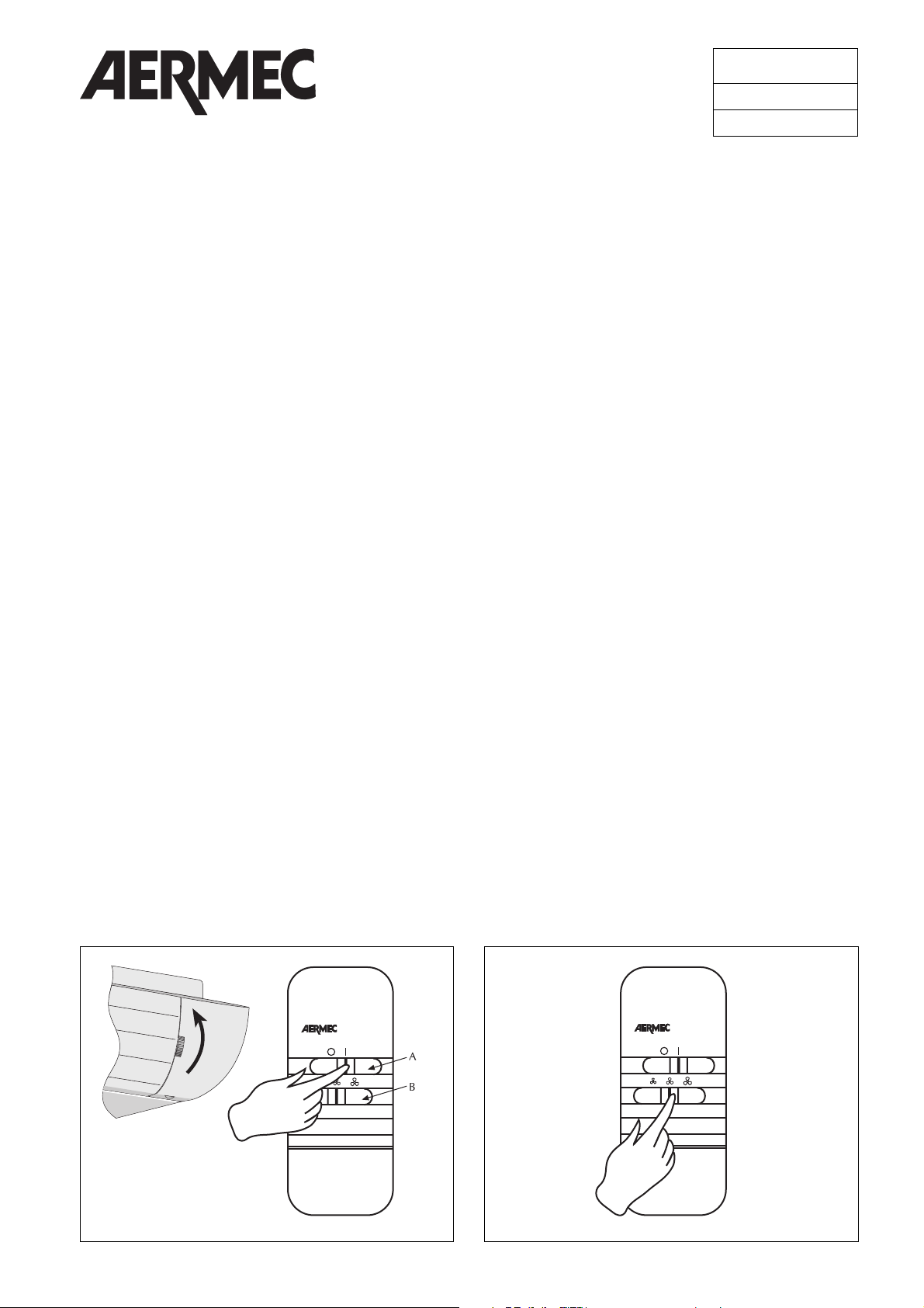
Il pannello comandi comprende (fig. 1):
– interruttore acceso-spento (A);
– commutatore delle tre velocità di ventilazione (B).
FUNZIONAMENTO DEL PANNELLO COMANDI
Per accendere/spegnere il ventilconvettore (fig.2):
– Aprire le alette (solo per le versioni FCX U ed OMNIA).
– Commutare la posizione del selettore superiore.
Per scegliere la velocità del ventilatore (fig.3):
– Commutare la posizione del selettore inferiore in base alla
velocità prescelta.
CONTROL PANEL PX2
The PX2 control panel for fancoils can be installed on board
the fancoil unit (only FCX AS and U) or in a remote position.
The assembly kit comprises the panel, the panel bracket for
on-board assembly and electrical connectors.
Each panel controls a single fancoil.
The control panel (fig. 1) includes:
– ON/OFF switch (A);
– three-speed fan operation selector (B).
OPERATING WITH CONTROL PANEL
To turn on/off the fan coil (fig.2):
– Open the louvers (only FCX U and OMNIA versions).
– Shift the upper button.
To select fan coil speed (fig.3)
– Switch over position of lower selector according to reque-
sted speed.
PANNEAU DE COMMANDE PX2
Le panneau de commande PX2 pour ventiloconvecteurs peut
être installé sur l’appareil (seulement pour le versions FCX AS et
U) ou dans une position à distance par rapport à l’unité de
climatisation. Le kit d’assemblage est constitué par le panneau
de commande, le support du panneau pour montage sur
l’appareil et les raccordements électriques.
Chaque panneau ne peut contrôler qu’un seul ventiloconvecteur.
Le panneau de commande comprend (fig. 1):
– interrupteur M/A (A);
– commutateur des trois vitesses de ventilation (B).
FONCTIONNEMENT DU PANNEAU COMANDI
Pour allumer/eteindre le ventilconvecteur (fig.2):
– Ouvrir les ailettes (seulement pour le versions FCX U et OMNIA).
– Pouser le bouton du haut.
Pour choisir la vitesse du ventilateur (fig.3)
– Commuter la position du selecteur inférieur selon la vitesse
préchoisie.
FERNBEDIENUNG
PX2
Die
Fernbedienung
PX2 für Gebläsekonvektoren
(nur für
Versionen FCX AS und U)
kann am Gerät oder entfernt vom
Gerät installiert werden.
Das Montagekit besteht aus der
Fernbedienung
, der Halterung
für die Anbringung am Gerät und den elektrischen Anschlüssen.
Jede
Fernbedienung
kann nur einen Gebläsekonvektor steuern.
Die
Fernbedienung
besteht aus (Abb. 1):
– Ein-/Ausschalter (A);
– Umschalter der drei Ventilatordrehzahlen (B).
BETRIEB DER BEDIENUNGSTAFEL
Einschalten/Ausschalten des Gebläsekonvektors: (fig.2):
– Die lamellen offnen (nur für Versionen FCX U und OMNIA).
– Die obene taste drücken.
Ventilatordrehzahl wählen (fig.3)
– Die Position des unteren Wahlschalters je nach der einge-
stellten Drehzahl umschalten.
Fig. 2
Fig. 1
Page 2
2
Fig. 3
Fig. 4
Fig. 5
FISSAGGIO A PARETE
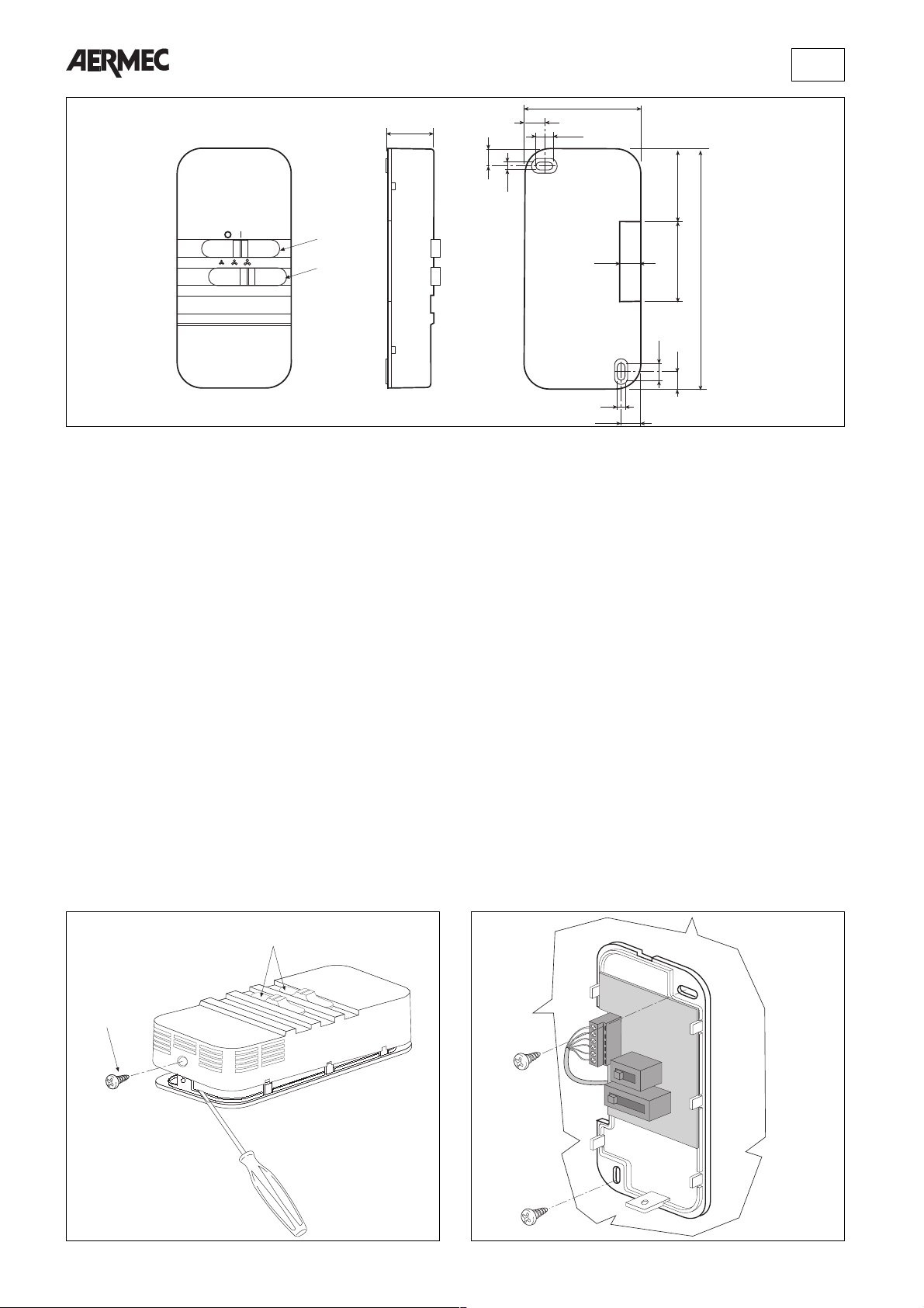
Per il fissaggio a parete del pannello comandi, procedere
come segue:
– allentare la vite di fissaggio (1 fig 4) ed estrarre l’involucro di
copertura e le leve di commutazione (2);
– scollegare i cavi forniti in dotazione da utilizzare solo in
caso di installazione a bordo macchina;
– fissare a parete il pannello utilizzando gli appositi fori (fig.5);
– introdurre lateralmente il cavetto ed eseguire il cablaggio
con riferimento agli schemi elettrici di figura 10 o 11;
– togliere le leve di commutazione dall’involucro di copertura.
– rimontare l’involucro di copertura ;
– bloccare la vite di fissaggio e riposizionare le leve di com-
mutazione.
WALL MOUNTING
To install the control panel, proceed as follows:
– loosen the screw (1 fig 4), remove the cover and the swit-
ching levers (2);
– disconnect the cables supplied with the unit they should be
used only in case of installation on board of the unit;
– position and secure the panel to the wall by means of the
holes (fig. 5);
– thread the lead through the side, then make wiring connec-
tions (refer to diagrams in figures 10 and 11);
– remove the switching levers from the cover;
– refit the cover;
– tighten the screw, then reposition the switches.
FIXATION SUR PAROI
Pour la fixation du panneau de commande sur paroi, procéder comme suit :
– desserrer les vis de fixation (1 fig. 4) et retirer la carrosserie
et les leviers de commutation (2);
– débrancher les câbles fournis de série à utiliser uniquement
en cas d’installation sur appareil;
– fixer le panneau à la paroi en utilisant les trous prévus à cet
effet (fig. 5);
– introduire latéralement le petit câble et effectuer le câblage
en suivant les schémas électriques des fig. 10 ou 11;
– retirer les leviers de commutation de la carrosserie;
– remonter la carrosserie;
– bloquer les vis de fixation et repositionner les leviers de
commutation.
WANDBEFESTIGUNG
Für die Wandbefestigung der Fernbedienung wie folgt verfahren:
– die Befestigungsschraube (1 Abb. 4) lockern, das Gehäuse
und die Umschalthebel (2) abnehmen;
– Die mitgelieferten Kabel abnehmen; diese sind nur bei der
Installation an der Maschine zu benutzen;
– die Fernbedienung mit Hilfe der vorgesehenen Bohrungen
(Abb. 5) an der Wand befestigen;
– das Kabel seitlich einführen und die Verkabelung gemäß
den Schaltplänen aus Abbildung 10 oder 11 ausführen;
– die Umschalthebel vom Gehäuse abnehmen.
– das Gehäuse wieder montieren;
– die Befestigungsschraube festziehen und die Umschalthebel
wieder einsetzen.
29
A
B
7,5
70
97,5
10,5
4
9,5
7,5
62
145
11
11
4
9,5
2
1
Page 3
3
INSTALLAZIONE A BORDO MACCHINA (FCX)
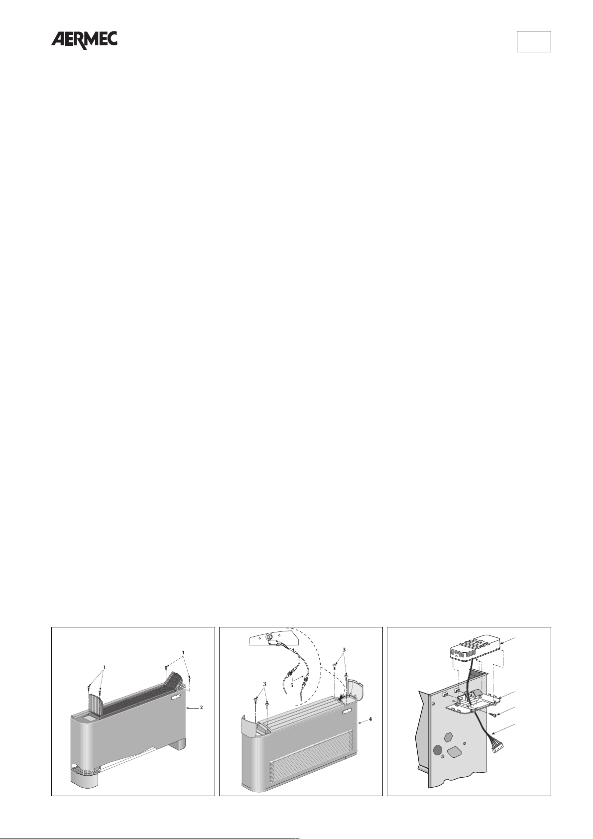
Per il montaggio procedere come segue :
– togliere il mantello:
per versione FCX - AS estrarre il filtro dell’aria, togliere le
quattro viti (1 fig. 6) che fissano il mantello al frutto e sfilare
il mantello di copertura (2).
per versione FCX - U togliere le quattro viti (3 fig. 7) che
fissano il mantello al frutto e sfilare il mantello di copertura
(4) avendo cura prima di staccare, se necessario, i connettori elettrici (5) del microinterruttore consenso ventilatore.
– Applicare il supporto pannello (6 fig.8) alla fiancata opposta ai
collegamenti idraulici, e fissarlo con la vite in dotazione (7);
– infilare i cavi del pannello (8 fig.8) nell’apposita feritoia,
quindi bloccare il pannello comandi (9) sul supporto;
– collegare la morsettiera pannello (10 fig.9) con la morsettie-
ra dell’unità (11).
Per il montaggio a bordo macchina i collegamenti sono forniti
a corredo.
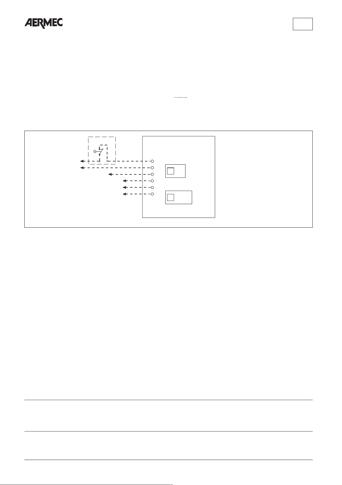
Per l’abbinamento del pannello comandi PX2 con i ventilconvettori versione FCX-U deve essere rispettato lo schema
elettrico di fig.11 inserendo in serie all’alimentazione del
pannello il microinterruttore (MS) che controlla l’apertura
della griglia di mandata (fig.7).
– riposizionare il mantello di copertura, quindi fissare le viti
precedentemente tolte;
– solo per versione FCX-AS, rimontare il filtro dell’aria.
ON-BOARD INSTALLATION (FCX)
To install the panel, proceed as follows:
– remove the cover:
FCX - AS version: extract the air filter by removing the four
screws (1 fig. 6) securing the cover to the contact block,
then slide off the cover piece (2);
FCX - U version: remove the four screws (3 fig. 7) securing
the cover to the contact block, then slide off the cover
piece (4) after having disconnected (as necessary) the electrical connectors (5) of the fan microswitch.
– Position the panel bracket (6 fig. 8) to the side of the unit
opposite to the water connectors, then secure with the
screws supplied (7);
– thread the panel wires (8 fig. 8) through the opening, then
fasten the control panel (9) to the bracket;
– connect the panel terminal block (10 fig. 9) to the terminals
of the unit (11).
Connectors for on-board assembly are supplied as standard
equipment.
When using the PX2 control panel with FCX-U series fancoils, refer to the wiring diagram shown in fig. 11. Series
connect the microswitch (MS) (controlling opening of the
delivery louvres fig. 7) in the power line to the panel.
– reposition the cover piece, then fasten with the screws pre-
viously removed;
– for FCX-AS versions: refit the air filter.
INSTALLATION SUR L’APPAREIL (FCX)
Pour le montage, procéder comme suit :
– retirer la carrosserie:
pour version FCX - AS, extraire le filtre de l’air, retirer les
quatre vis (1 fig. 6) fixant la carrosserie au châssis et ôter la
carrosserie (2).
Version FCX - U, retirer les quatre vis (3 fig. 7) fixant la carrosserie au châssis et ôter la carrosserie (4) en ayant soin de
débrancher d’abord, si nécessaire, les connecteurs électriques (5) du micro-interrupteur de validation du ventilateur.
– Appliquer le support du panneau (6 fig. 8) sur le flanc
opposé aux raccordements hydrauliques et le fixer avec la
vis fournie de série (7);
– introduire les câbles du panneau (8 fig. 8) dans la fente pré-
vue à cet effet puis bloquer le panneau de commande (9)
sur le support;
– raccorder le bornier du panneau (10 fig. 9) au bornier de
l’unité (11).
Pour le montage sur l’appareil, les raccordements sont fournis
avec l’appareil.
Pour associer le panneau de commande PX2 aux ventiloconvecteurs version FCX-U, respecter le schéma électrique
de la fig. 11 en branchant, en série avec l’alimentation du
panneau, le micro-interrupteur (MS) qui contrôle l’ouverture de la grille de refoulement (fig. 7).
– remettre la carrosserie puis fixer les vis précédemment
retirées;
– pour version FCX-AS seulement, remonter le filtre de l’air.
INSTALLATION AM GERÄT (FCX)
Für die Montage wie folgt verfahren :
– die Abdeckplatte abnehmen:
bei Version FCX - AS den Luftfilter herausnehmen, die vier
Schrauben lösen (1 Abb. 6), die die Platte an der
Anschlußhalterung befestigen und die Abdeckplatte (2)
herausziehen;
bei Version FCX - U die vier Schrauben lösen (3 Abb. 7),
die die Platte an der Anschlußhalterung befestigen und die
Abdeckplatte (4) herausziehen. Falls erforderlich, zuvor die
elektrischen Verbinder (5) des Mikroschalters für die
Ventilatorzustimmung trennen.
– Die Halterung der Fernbedienung (6 Abb. 8) an der den
Wasseranschlüssen gegenüberliegenden Seite anbringen
und mit der mitgelieferten Schraube (7) befestigen;
– die Kabel der Fernbedienung (8 Abb. 8) in den vorgesehe-
nen Schlitz einführen und das Fernbedienung (9) an der
Halterung befestigen;
– das Klemmenbrett der Fernbedienung (10 Abb. 9) mit dem
Klemmenbrett der Einheit verbinden (11).
Für die Montage am Gerät sind die Anschlusskabeln mitgeliefert.
Für die Kopplung der Fernbedienung PX2 mit den
Gebläsekonvektoren Version FCX-U den Schaltplan aus
Abb. 11 berücksichtigen und an der Zuleitung des
Schaltfeldes den Mikroschalter (MS) in Reihe schalten, der
die Öffnung des Auslaßgitters steuert (Abb. 7).
– die Abdeckplatte wieder anbringen, danach die zuvor abge-
nommenen Schrauben wieder festschrauben;
– nur bei Version FCX-AS den Luftfilter wieder montieren.
Fig. 7
Fig. 6
Fig. 8
9
6
7
8
Page 4
I dati tecnici riportati nella presente documentazione non sono impegnativi.
La AERMEC S.p.A. si riserva la facoltà di apportare in qualsiasi momento tutte le
modifiche ritenute necessarie per il miglioramento del prodotto.
Technical data shown in this booklet are not binding.
AERMEC S.p.A. shall have the right to introduce at any time whatever modifications
deemed necessary to the improvement of the product.
Les données mentionnées dans ce manuel ne constituent aucun engagement de notre
part. AERMEC S.p.A. se réserve le droit de modifier à tous moments les données considérées nécessaires à l' amelioration du produit.
Im Sinne des technischen Fortschrittes behält sich AERMEC S.p.A. vor, in der
Produktion Änderungen und Verbesserungen ohne Ankündigung durchzuführen.
4
PX2
1
2
3
4
5
6
01
1 23
L
N
MV (Min)
MV (Med)
MV (Max)
MV
MS
Fig. 9
MS = Microinterruttore griglia (FCX U - OMNIA)
Louvre microswitch (FCX U - OMNIA)
Micro-interrupteur grille (FCX U - OMNIA)
Mikroschalter Gitter (FCX U - OMNIA)
MV = Motore ventilatore
Fan motor
Moteur ventilateur
Ventilatormotor
PX2 = Scheda di controllo
Electronic control board
Platine de contrôle
Steuerschaltkreis
= Collegamenti a cura dell’installatore
Connections to be made by installeur
Branchements aux bons soins de l’installateur
Bauseitig durchzuführende verdrahtung
Per il montaggio a bordo macchina i collegamenti sono forniti a corredo.
Connectors for on-board assembly are supplied as standard equipment.
Pour le montage sur l’appareil, les raccordements sont fournis avec l’appareil.
Für die Montage am Gerät sind die Anschlusskabeln mitgeliefert.
LEGENDA • READING KEY • LEGENDE • LEGENDE
Gli schemi elettrici sono soggetti ad aggiornamento; è opportuno fare riferimento allo schema elettrico allegato all' apparecchio.
Wiring diagrams may change for updating. It is therefore necessary to refer always to the wiring diagram inside the units.
Les schémas électriques peuvent être modifies en conséquence des mises à jour. Il faut toujours se référer aux schémas électriques dans les appareils.
Die Schaltschemas können geändert werden; es empfiehlt sich immer auf das mit dem Zubehör verpackte El. Schaltschema zu beziehen.
SCHEMI ELETTRICI • WIRING DIAGRAMS • SCHEMAS ELECTRIQUES • SCHALTPLANE
AERMEC S.p.A.
I-37040 Bevilacqua (VR) - Italia
Via Roma, 44 - Tel. (+39) 0442 633111
Telefax (+39) 0442 93730 - (+39) 0442 93566
 Loading...