

AERMEC HRS 060, HRS 090, HRS 090W, HRS 160, HRS 160W Installation, Use And Maintenance Manual
...
HEAT RECOVERY UNIT
Installation, Use and Maintenance Manual
HRS-HRS W
4530600_00 dated 0904

A the Manufacturer is constantly committed in the continuous improvement of its entire production, the aesthetic and dimensional features, the technical data, equipment and accessories may be subject to variation.
!
This instruction book is an integral part of the appliance and as a consequence must be kept carefully and must ALWAYS
accompany the appliance even if transferred to other owners or users or transferred to another plant. If damaged or lost,
request another copy from the Manufacturer.
!
Repair and maintenance interventions must be carried out by authorised staff or staff qualified according to that envisioned
by this book. Do not modify or tamper with the appliance as dangerous situations can be created and the appliance manufacturer will not be liable for any damage caused.
!
After having removed the packaging ensure the integrity and completeness of the content. If this is not the case, contact the
Company that sold the appliance.
!
The appliances must be installed by enabled companies in compliance with the Law 5 March n° 46 which, at the end of the
job issues a declaration of conformity regarding installation to the owner, i.e. in compliance with the Standards in force and
the indications supplied in this book.
!
Any contractual or extracontractual liability of the Manufacturer is excluded for injury/damage to persons, animals or objects
owing to installation, regulation and maintenance errors or improper use.
We remind you that the use of products that employ electrical energy and water requires that a number of essential safety
rules be followed, including:
This appliance must not be used be children and unaided disabled persons.
It is prohibited to touch the appliance when you are barefoot and with parts of the body that are wet or damp.
It is prohibited to perform any maintenance or cleaning operation before having disconnected the appliance from the
mains electricity network, by positioning the plant master switch at "off"
It is prohibited to modify the safety or adjustment devices without the manufacturer’s authorisation and precise instructions
It is prohibited to pull, detach or twist the electrical cables coming from the unit even if it is disconnected from the electrical mains
It is prohibited to climb onto the unit, sit on it and/or rest any type of object on it.
It is prohibited to spray or jet water directly onto the unit.
It is prohibited to open the doors for accessing the internal parts of the appliance without first having switched off the master switch of the "system".
It is prohibited to disperse, abandon or leave the packing materials within the reach of children, as they are a potential
source of danger
page 2
Heat Recovery Units Installation, Use and Maintenance Manual

Important Note
The heat recovery unit is a machine designed and built exclusively to change air in the civil environments,
incompatible with toxic and inflammable gases. Therefore it cannot be used in those environments where the
air is mixed and/or altered by other gaseous composites and/or solid particles.
The use of the same for different purposes from those envisioned, not conform to that described in this
manual, will make any direct and/or indirect liability of the Manufacturer automatically become null and void.
SYMBOLS
!
WARNING
!
DANGER
i
DANGER RISK F ELECTRIC SHOCK
f
ATTENTION ONLY AUTHORISED STAFF
PROHIBITION
page 3
Heat Recovery Units Installation, Use and Maintenance Manual

INDEX
SECTION 1 - GENERAL FEATURES
1.1 Manual presentation page 5
1.2 Construction features page 5
1.3 Orientations possible for HRS range horizontal models page 6
1.4 HRS range unit technical data page 7
1.5 HRS - HRSW range unit technical data page 8
1.6 Accessories available page 8
SECTION 2 - TRANSPORT
2.1 Packaging page 11
2.2 Handling and transport
2.3 Control and receipt
2.4 Storage
SECTION 3 - INSTALLATION AND START-UP
page 11
3.1 Safety Standards
3.2 Preliminary operations page 12
3.3 Choosing the place of installation page 12
3.4 Positioning the machine page 12
3.5 Connection to the ducts page 13
3.6 Hydraulic connections
3.7 Any installation of the section with water coil HRS_CS page 14
3.8 Hydraulic connection of the section with water coil HRS_CS page 15
SECTION 4 - ELECTRIC CONNECTIONS page 15
4.1 Electronic speed adjuster HRS_SC page 16
4.2 Wiring diagrams page 17
SECTION 5 - CONTROLS BEFORE START-UP page 22
SECTION 6 - ROUTINE MAINTENANCE
6.1 Warnings page 22
6.2 Monthly checks
6.3 Yearly checks page 24
SECTION 7 - DISPOSAL page 24
DECLARATION OF CONFORMITY page 25
page 4
Heat Recovery Units Installation, Use and Maintenance Manual

INTRODUCTION
The heat recovery units for horizontal installation are characterised by small dimensions and easy assembly.
The heat recovery units allow to join maximum environmental comfort with sure energy saving.
Forced ventilation must be created in current air conditioning and treatment plants, which leads to the expulsion of treated air,
determining large energy consumption and increase in costs.
The HRS heat recovery unit range intend to solve these problems using a static heat recovery unit that saves more than 50%
of the energy that would otherwise be lost.
SECTION 1 - GENERAL FEATURES
1.1 Manual presentation
This manual states the information and that deemed necessary for transport, installation, use and maintenance of the HRS
range heat recovery units.
The user will find that which is normally useful to know for correct safe installation of the heat recovery units described.
Failure to comply with that described in this manual and inadequate installation of the heat recovery unit causes the annulment
of the warranty that the Manufacturer gives its heat recovery units. Moreover, the Manufacturer is not liable for any direct and/or
indirect damage due to incorrect installation or damage caused by units installed by unskilled and unauthorised staff. On purchase, check that the machine is integral and complete.
Any claims must be made in writing within 8 days from receipt of the goods.
1.2 Construction features
• Panels realised in Aluzink sheet steel, removable for inspection and maintenance.
• Acoustic and heat insulation of the panels using polyethylene/polyester with average thickness of 20 mm.
• Fresh air intake and double intake centrifugal type expulsion fans (for the HRS 30 model with simple intake) with directly coupled electric motor.
• Fan body mounted onto anti-vibration mounts so as not to transmit any vibrations.
• Air filters with G3 efficiency, easily extractable laterally, to allow periodical cleaning.
for the HRS range
• Terminal boards on machine to ease the electric connections and fan control.
• Condensate drip tray in ABS with low condensate drain connection.
page 5
Heat Recovery Units Installation, Use and Maintenance Manual

1.3 HRS possible orientations and clearance
• STANDARD ORIENTATION TYPE 03
Depending on the configuration of the network and the space available, it is possible to choose the other 3 orientations
AT THE TIME OF PLACING THE ORDER, (TYPE 01 - 02 - 04).
Heat Recovery Units Installation, Use and Maintenance Manual
page 6
Gli orientamenti raffigurati sono relativi alla macchina vista dall’alto
La batteria di post-riscaldamento (ad acqua) disponibile solo sulla versione HRS-W /
The configurations are referred to the top view
The post-heating water coils is available only for model HRS-W
ORIENTAMENTO TIPO 01 / CONFIGURATION TYPE 01
ORIENTAMENTO TIPO 02 / 02
ORIENTAMENTO TIPO 03 /
(Tipo standard / )$')-&)
ORIENTAMENTO TIPO 04 /
Aria espulsa / Exhaust air
Aria di rinnovo / Fresh air
Aria espulsa / Exhaust air
Aria di rinnovo / Fresh air
Aria espulsa / Exhaust air
Aria di rinnovo / Fresh air
Aria espulsa / Exhaust air
Aria di rinnovo / Fresh air

Orientamento 1 e 2 / Configuration 1 and 2 Orientamento 1 e 2 / Configuration 3 and 4
HRS mod. 030 - 060
HRS mod. 090-160-190-230-300-390
La batteria di post-riscaldamento ad acqua disponibile solo sulla versione MRS_W /
T
he post-heating water coils is available only for model HRS-W
Heat Recovery Units Installation, Use and Maintenance Manual
page 7
MODEL
HRS 030 HRS 060
HRS 090
HRS 090W
HRS 160
HRS160W
HRS 190
HRS190W
HRS 230
HRS 230W
HRS 300
HRS 300W
HRS 390
HRS 390W
Size
A mm 990 990 1140 1300 1380 1650 1650 1750
B mm 290 290 410 500 500 600 600 600
C mm 750 750 860 860 960 1230 1230 1230
D mm / / 260 290 310 410 410 410
D1 mm / / 95 77 87 91 91 116
E mm / / 210 310 330 410 410 410
F mm / / 220 225 225 288 321 321
F1 mm / / 115 109 129 152 135 160
G mm / / 200 255 255 255 280 280
G1 Ø gaz / / 3/4 3/4 3/4 3/4 3/4 3/4
Y mm / / 50 75 75 162 125 125
Ø mm 160 200 / / / / / /
Øi mm 460 355 / / / / / /
Weight kg 41 45 80 125 138 160 174 190
1.4 HRS range unit technical data

1.6 Accessories available
1.5 HRS - HRS W range unit technical data
(1)
Values referring to the nominal air flow rate including recovery unit and filters
(2) Noise pressure level: values referring to 1.5 metres from machine intake in free field. The operational noise level differs from the values indicated according to the functioning conditions, the reflex
noise and peripheral noise
(3) Input power at the electric mains.
(4) Can be adjusted electronically with WM regulator
MODELLO / MODEL HRS 030 060 090 160 190 230 300 390
Portata aria nominale / Nominal air flow m³/h 300 620 920 1580 1850 2250 2950 3920
Pressione statica utile / External static pressure
(1)
Pa 45 55 65 70 77 80 100 100
Assorbimento max. totale macchina / Total max absorbed current
A 0,75 1,8 2,2 4,4 4,8 5,2 8,3 5
Pressione sonora / Sound pressure level
(2)
db (A) 43 51 50 53 52 51 54 56
VENTILATORI / FANS 030 060 090 160 190 230 300 390
Potenza disponibile all'asse / Power input W 92 x 2
(3)
90 x 2 147 x 2 350 x 2 350 x 2 350 x 2 550 x 2 750 x 2
Poli / Poles n° 4
Numero velocità / Speed number n° 1
(4)
3
(5)
1
(6)
Grado di protezione / Enclosure protection IP 44 55 44 55
Classe di isolamento / Insulation class F
Alimentazione elettrica / Electrical supply V/ph/Hz 230/1/50 400/3/50
Heat Recovery Units Installation, Use and Maintenance Manual
page 8
It is possible to intake or expel the air frontally and
laterally by simply changing the position of the
panels, as illustrated at the side.
This can simplify the realisation of the air ducts
greatly, bringing an effective saving to installation
times.
Accessories compatibility
HRS 090 HRS 160 HRS 190 HRS 230 HRS 300 HRS 390
HRS 030 HRS 060 HRS 090W HRS 160W HRS 190W HRS 230W HRS 300W HRS 390W
HRS090CS ✔
HRS160CS ✔
HRS190CS ✔
HRS230CS ✔
HRS300CS ✔
HRS390CS ✔
HRS090ED ✔
HRS160ED ✔
HRS190ED ✔
HRS230ED ✔✔ ✔
HRS090S ✔
HRS160S ✔✔
HRS230S ✔✔ ✔
HRS030SC ✔
HRS060SC ✔
HRS01AT * ✔✔✔✔✔ ✔
PX ✔✔✔✔✔
PX2 ✔✔✔✔✔
* Accessory installed in the factory, compatible only with HRS W version, to be requested when placing the order.
• HRS_CS: Section of water cooling/heating (with
stainless steel condensate drip tray).
• HRS_ED: Regulation shutter.
• HRS_S: N° 4 circular connection kits for direct
connection of the unit to the circular conduits.
- HRS090S (ø 315 mm)
- HRS160S (ø 355 mm)
- HRS230S (ø 400 mm)
• HRS_SC: Electronic speed regulator.Anti-freeze
thermostat, allows to control that the temperature does not fall below a pre-established value. .
Accessory installed in the factory, to be
requested when placing the order for the
HRS W version.
• PX: Control panel with switch-over.
Wall installation. (from size 090 to 300)
• PX2: Control panel with switch-over. Wall instal-
lation (from size 090 to 300)

Heat Recovery Units Installation, Use and Maintenance Manual
page 9
1.7 Accessories technical data
HRS_W UNIT WITH WATER POST-HEATING SECTION
The use of the coil is requested when post-heating is necessary and must be fixed directly inside the heat recovery unit.
Values referring to the following conditions: Water 70/60 °C; Air inp. T = 8°C; Nominal air flow rate.
HRS_ED ADJUSTMENT DAMPER
The adjustment damper is made up from a galvanised sheet steel frame with adjustable louvered fins.
Model B (mm) A (mm)
HRS090ED 260 210
HRS160ED 290 310
HRS190ED 330 310
HRS230-ED 410 410
BATTERIA POST-RISCALDAMENTO
WATER HEATING COIL - BCR
090 160 190 230 300 390
Resa termica / Heating capacity kW 8.2 12.2 14.4 20.3 24.2 29.9
Geometria / Geometry 25x22 25x22 25x22 25x22 25x22 25x22
Tubi per rango / Pipes per row n° 14 18 18 22 22 22
Ranghi / Rows n° 2 2 2 2 2 2
Passo alette / Fins spacing mm 2.5 2.5 2.5 2.5 2.5 2.5
Temp. uscita aria / Outlet air temperature °C 33.4 30.8 30.2 33.2 31.3 29.7
Perdita di carico lato aria / Air pressure drop Pa 25 32 35 24 36 38
Perdita di carico lato acqua / Water pressure drop kPa 8 14 15 17 22 30
Diametro collettori / Connection diameter Ø gas 3/4 3/4 3/4 3/4 3/4 3/4
Peso / Weight kg 2.5 2.5 2.5 5 5 6.5
HRS_CS SECTION WITH WATER COIL
The HRS_CS module contains a water coil and must be positioned outside the machine in front of the introduction vent.
The condensate drip tray in stainless steel with low condensate drain connection.
Model 090 160 190 230 390
A (mm) 500 600 700 700 700
B (mm) 410 500 500 600 600
C (mm) 450 450 480 660 710
D (mm) 260 290 310 410 410
E (mm) 210 310 330 410 410
Ø1 (gas) 3/4" 3/4" 3/4" 3/4" 1"
Ø2 (mm) 22 22 22 22 22

Heat Recovery Units Installation, Use and Maintenance Manual
page 10
HRS with HRS_CS
Geometry
Pipes for row n°
Rows n°
Louver pitch mm
Heating
Heating capacity
(1)
kW
Air outlet temperature °C
Water flow rate m3/h
Water side pressure drops kPa
Air side pressure drops Pa
Cooling
Cooling capacity
(2)
kW
Sensitive cooling capacity kW
Air outlet temperature °C
Water flow rate m3/h
Water side pressure drop kPa
Air side pressure drop Pa
25x22 25x22 25x22 25x22 25x22 25x22
16 22 25 26 26 26
333333
2,1 2,1 2,1 2,1 2,1 2,1
HRS090 HRS160 HRS190 HRS230 HRS300 HRS390
12 19,65 23,7 30,5 37 46,2
45 43,4 45 46,5 43,7 41,5
1,02 1,65 2,08 2,64 3,1 3,73
4 11 20 18 22 21
28 41 39 27 40 53
HRS090 HRS160 HRS190 HRS230 HRS300 HRS390
5 8,8 11,1 14,7 17,4 20,93
3,3 5,8 7,2 9,4 11,4 13,9
19,2 18,9 18,2 17,3 18,3 19,13
0,92 1,65 2,16 2,87 3,2 3,83
4 15 27 26 30 30
38 50 53 45 48 60
HRS – CS TECHNICAL DATA
(1) Values referring to: In/out water 70/60 °C; Air inp. T = 8°C and nominal air flow rate.
(2) Values referring to: Input air temp. 30 °C, RH 50%. In/out water temp. 7/12 - °C. Nominal air flow rate

2.1 Packaging
• The heat recovery unit and their accessories are inserted into cardboard boxes (or polyethylene bubble pack), which
must remain integral until assembly.
2.2 Handling and transport
• Depending on the weight, to handle use suitable means envisioned by the 89/391/EEC Directive and successive
amendments.
• The weight of each individual machine is stated on the following manual.
• Great care must be taken with loading operations. All machines must be loaded and stored on the lorry, positioning
relevant spacers in order to protect all projecting parts such as hydraulic connections, handles and hinges.
2.3 Control and receipt
On receipt of the unit please control al parts in order to check that they have not been damaged during transport.
Any damage must be communicated to the carrier, affixing the reserve clause on the way bill, specifying the type of
damage.
2.4 Storage
In the case of prolonged storage, keep the machines protected from dust and away from sources of vibrations and
heat.
The Manufacturer declines all liability for damage owing to bad draining or no protection from atmospheric
agents.
3.1 Safety Standards
The Manufacturer declines all responsibility for the failure to comply with the Safety and Accident-prevention
Standards described below.
It also declines all liability for damage caused by improper use of the heat recovery unit and/or modifications performed without authorisation.
• Specialised staff must perform installation.
• Wear suitable and accident-prevention clothing during installation, for example: goggles, gloves etc. as indicated in
the 686/89/EEC Standard and successive amendments.
• During installation operate in complete safety, clean environment and free from obstructions.
• Respect the laws in force, in the country in which the machine is installed, relative to use and disposal of packaging
and the products used for cleaning and maintenance of the machine, as well as complying with that recommended
by the producer of these products.
• Before starting the unit, check the perfect integrity of the various components of the entire plant.
• Do not touch moving parts or intervene between these.
• Do not perform maintenance and cleaning until the electric line has been connected.
• The maintenance and replacement of damaged or worn parts must only be performed by specialised staff and following the indications given in this manual.
• The spare parts must correspond to the requirements defined by the Manufacturer.
• If the heat recovery unit must be dismantled, follow the envisioned anti-pollution standards.
N.B. When using the heat recovery unit, the installer and user must consider and solve all risks connected to the
plant. For example, risks deriving from the entry of foreign bodies or risks due to the conveying of dangerous inflammable or toxic gases at a high temperature.
Manuel d'Installation et de Maintenance des Récupérateurs de Chaleur
!
SECTION 2 - TRANSPORT
!
SECTION 3 - INSTALLATION AND START-UP
page 11

3.4 Positioning the machine
Some assembly sequences are illustrated below:
1. Drill the ceiling and fix four M8 threaded tie-rods, as indicated in the figure.
2. Position the unit on the four tie-rods
3. Block the unit by fastening the fixing bolt
Model
HRS
030 060 090 160 190 230 300 390
A (mm) 930 930 1075 1240 1320 1590 1590 1690
B (mm) 690 690 800 800 900 1170 1170 1270
3.2 Preliminary operations
.
• Check the perfect integrity of the various components of the unit.
• Check that the packaging contains the accessories for installation and the documentation.
• Transport the packaged section as near as possible to the place of installation.
• Do not place tools or weights on the packaged unit.
3.3 Choice of place of installation
• Position the heat recovery unit on a solid structure that does not cause vibrations and that can support the weight of
the machine.
• Do not position the unit in places where inflammable gases, acid and aggressive and corrosive substances are present, which can damage the various components irreparably.
• Envision a minimum free space as indicated in the following figures, in order to make installation and routine and
extraordinary maintenance possible.
HRS range models
HRS model 030 060 090 160 190 230 300 390
A (mm) 300 300 350 400 400 450 450 450
page 12
Heat Recovery Units Installation, Use and Maintenance Manual
HRS range models:
with the purpose of favouring the regular flow of condensate, it is advised to mount the machine inclined by 3 mm
towards the condensate drain.

3.6 Hydraulic connections
• The installation and connection operations of the hydraulic pipes are operations that can compromise the good functioning of the plant or worse, cause irreversible damage to the machine. These operations must only be performed
by specialised staff.
3.5 Connection to the ducts
• The ducts must be dimensioned depending on the plant and the aeraulic features of the unit fans. An incorrect calculation
of the ducting causes a loss of power or the intervention of any devices present on the plant.
• It is recommended to use insulated ducts to prevent the formation of condensate and attenuate the noise level.
• To prevent transmission of any machine vibrations into the environment it is recommended top lace an anti-vibration joint
between the fan vents and the ducts. The electrical continuity must however be guaranteed between the duct and the machine via the earth cable.
IMPORTANT: IT IS PROHIBITED TO START THE HRS UNIT IF THE FAN VENTS ARE NOT DUCTED OR PROTECTED WITH ACCIDENT-PREVENTION
MESH ACCORDING TO UNI 9219 STANDARD AND SUCCESSIVE AMENDMENTS
%$$()'"$%$$)"%$'$
• The HRS range units are all equipped with condensate drip tray.
• The stainless steel condensate drip tray has a drain with D. 21 mm.
• The drain system must have a suitable siphon for preventing the undesired entry of air
into the depressurised systems or the undesired exit of air in pressurised systems. This
siphon is also useful to prevent the infiltration of odours or insects.
• The dimensioning and the version of the siphons in the case of the depressurised tray
(or pressurised) must guarantee that H>P, where P expressed in mm.w.c. is equal to the
useful static pressure of the machine installed (figure at the side).
• The siphon must finally have a cap for cleaning the lower part or must however allow
quick disassembly for periodical cleaning.
• The route f the condensate drain pipe must always slope towards the outside. It must
also be as short as possible and with the least number of bends.
page 13
Heat Recovery Units Installation, Use and Maintenance Manual
• Always make sure that the condensate flow pipe does not stress the unit drain connection, envisioning appropriate bracketing if necessary.
• The position of the drain is made clear in the following table
HRS range models
• To access the drain, remove the base counter panel as highligh-
ted in the figure at the side.
Model
HRS
030 060 090 160 190 230 300 390
A (mm) 355 315 640 810 840 965 965 965
B (mm) 225 195 250 250 151 290 290 290
Hole (mm) 28 28 28 28 28 28 28 28

$-"$()##)"%$%)!()"%$+")!+)'%"#
A plastic bag is also supplied with the section with water coil. It contains:
- n. 4 anti-vibration mounts
- n. 4 attachment brackets
- n. 8 M8 x 20 screws
- n. 4 notched washers diam. 8 mm.
%(")"%$"$
• The section with water coil must be positioned in front of the machine flow vent.
The collector marked by the "WATER OUTLET" label must be at the side of the machine (1)
• Remove the side panel of the section with water coil, loosening the screw fasteners (2)
• Partially tighten the 4 M8 screws into the inserts present at the tops of the machine event (3)
• Hitch the section with water coil to the machine, passing the head of the projecting screws through the holes and
push the section down, in a way that the head of the screws is blocked in the upper part of the hole. Access the 4
screw fasteners from the side of the section and tighten them (4)
• Fix the side of the section again (5)
"#"$ ",)*'
• Fix the supplied brackets to the section using the 4 M8 screws to be
tightened in the relevant inserts (6)
• Fix four threaded M8 tie-rods to the ceiling in correspondence with
the brackets. Block the unit by tightening the fixing bolts (7)
1
2 3
4
5 6
7
Attention: the installation of the section with water coil leads to additional pressure drops
in the introduction circuit. These drops are stated in the table on page 9 (“Coil air side pressure drop”)
page 14
Heat Recovery Units Installation, Use and Maintenance Manual

Heat Recovery Units Installation, Use and Maintenance Manual
page 15
-'*#"%$$)"%$%)!()"%$+")!+)'%"#
• The installation and connection operations of the pipes are operations that can compromise the good functioning of the plant or worse, cause irreversible damage to the machine. These operations must only be performed by specialised
staff.
• The section with water coil is supplied with "male" connections with gas threading.
• Tightening must be performed carefully to prevent damage to the copper collectors in the coil.
• The route of the pipes must be studied in a way not to create obstacles if the unit coil is extracted.
• Water inlet/outlet must be such to allow countercurrent heat exchange: follow the indications of the WATER INLET and WATER
OUTLET plates
• Envision a high vent valve and a low discharge valve.
• Clamp the pipes adequately to the outside of the section to prevent the weight being unloaded onto the coil.
• When connection has been made, push the external gasket well against the panel to prevent seepage of air.
• Insulation must be flush to the panel in order to prevent the danger of condensation.
• Envision anti-freeze device.
• Envision on-off valves to isolate the coil from the rest of the circuit in the case of extraordinary maintenance.
• In the case of installation in zones with particularly cold climates, empty the plant for long standstill periods.
3.8.1 Condensate drain connection of the section with water coil HRS_CS
• The stainless steel condensate drip tray has a drain with external
diameter of 22 mm.
• The drain system must have a suitable siphon in order to prevent
the undesired entry of air into the depressurised system. This
siphon is also useful to prevent the infiltration of odours or
insects.
• The dimensioning and version of the siphon must guarantee that
H ³ P, where P expressed in mm.w.c and equal to the useful static pressure of the machine installed.
• The siphon must finally have a cap for cleaning the lower part or
must however allow quick disassembly for cleaning.
• The route of the condensate drain pipe must always slope
towards the outside.
• Make sure that the condensate flow pipe does not stress the unit
drain connection.
SECTION 4 - ELECTRIC CONNECTIONS
• The electric connections to the control board must be made by specialised staff according to the diagrams supplied.
• Make sure that the voltage and the frequency stated on the plate correspond with those of the electric connection
line.
• The use of adapters, multiple sockets and/or extensions is not allowed to power the heat recovery unit.
• It is the installer's responsibility to assemble the unit as near as possible to the power supply isolator and
the necessary to protect the electric parts.
• Connect the unit to an efficient earth socket, using the relevant screw inserted in the unit itself.
Before starting any operation, make sure that the main power supply line has been isolated
Make the connection using cables with suitable section for the power used and in compliance with the local
regulations. Their dimension must be such to realise a voltage drop in the start-up phase, lower by 3% of the
nominal value

4.1 Electronic speed adjuster HRS_SC (mod. 30 - 60)
The speed adjuster is suitable for wall installation and allows the adjustment of the fan with one-speed single-phase
motor. Two adjuster models are envisioned according to the fan motor input current: HRS 030SC and HRS060SC.
The following are present on the front of the contropanel:
• on/off switch
• knob for continuous speed adjustment.
Installation et montage
1. Loosen the 4 screw fasteners and slide out the cap;
2. Fix the small base to the wall using the relevant
holes, at about 1.5 metres from the floor;
3. Make the electric connections;
4. Re-position the cap and tighten the screws.
holes
for wall fixing
cap screw
fasteners
cap screw
fasteners
page 16
Heat Recovery Units Installation, Use and Maintenance Manual

Heat Recovery Units Installation, Use and Maintenance Manual
page 17
4.2 Wiring diagrams
HRS 030 – 060 WITH ELECTRONIC ADJUSTER HRS_SC WIRING DIAGRAM
HRS 030 – 060 DIRECT WIRING DIAGRAM
A tratteggio sono evidenziati i collegamenti da effettuarsi a cura dell’installatore. / Dashed lines show the connections to be carried out by the installer.
Tutte le linee devono essere protette all’origine a cura dell’installatore. / All lines must be protected at the origin by the installer.
A tratteggio sono evidenziati i collegamenti da effettuarsi a cura dell’installatore. / Dashed lines show the connections to be carried out by the installer.
Tutte le linee devono essere protette all’origine a cura dell’installatore. / All lines must be protected at the origin by the installer.
FACTORY CONNECTIONS
FACTORY CONNECTIONS
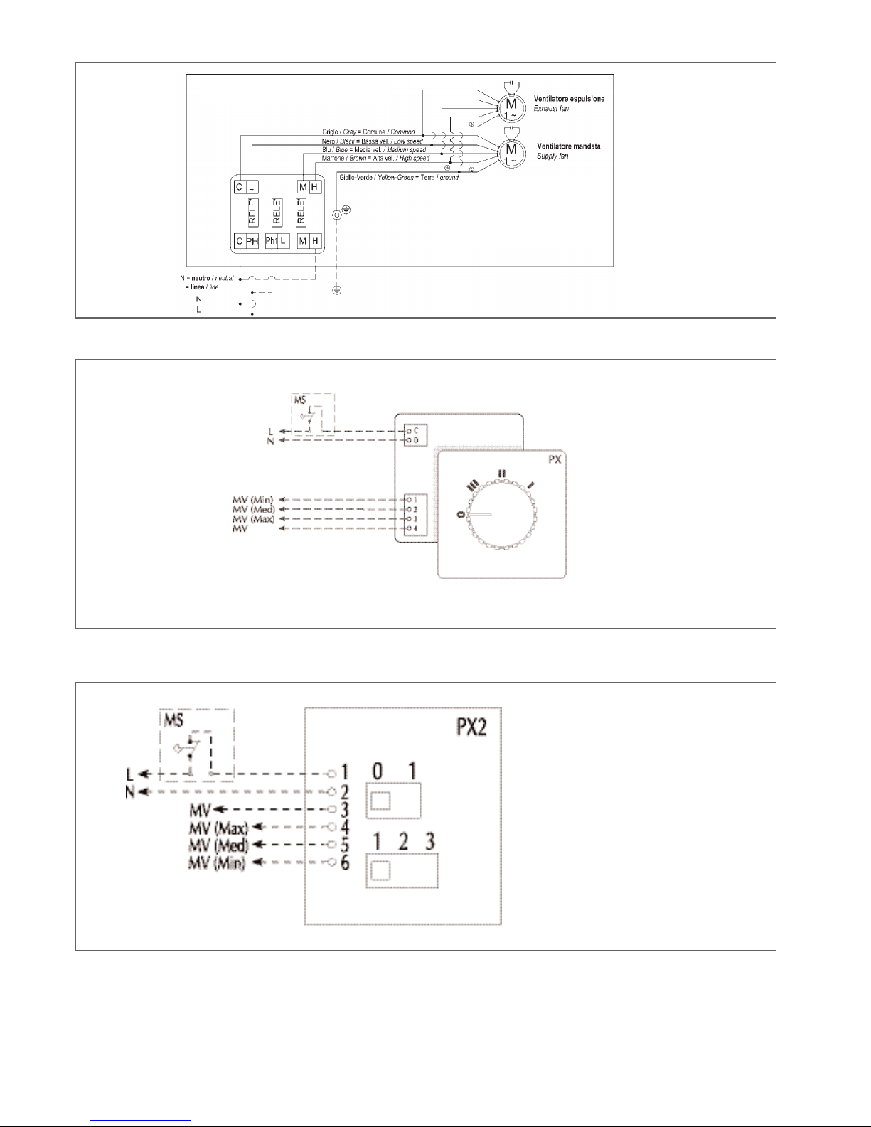
HRS 090 - 160 - 190 WITH SPEED SELECTOR SWITCH PX WIRING DIAGRAM
HRS090 - 160 - 190 DIRECT WIRING DIAGRAM
HRS 090 - 160 - 190 WITH SPEED SELECTOR SWITCH PX2 WIRING DIAGRAM
Nello schema è indicato il funzionamento alla massima
velocità.Per il funzionamento
alla media velocità collegare il
neutro con il morsetto M, per
la bassa con il morsetto L.
The diagram shows operation
at the high speed. For the
medium speed connect the
neutral with clamp named M,
for the low speed with clamp
named L.
FACTORY CONNECTIONS
A tratteggio sono evidenziati i collegamenti da effettuarsi a cura dell’installatore.
Tutte le linee devono essere protette all’origine a cura dell’installatore.
Dashed lines show the connections to be carried out by the installer.
All lines must be protected at the origin by the installer.
C = comune ventilatori / common fan
Ph = fase / phase
Ph1 = comune relé / common relays
L = bassa velocità / low speed
M= media velocità /medium speed
H= alta velocità / high speed
The connections that the installer must make are
dotted.
All lines must be protected at the origin by the
installer.
Dashed lines show the connections to be carried
out by the installer.
All lines must be protected at the origin by the
installer.
page 18
Heat Recovery Units Installation, Use and Maintenance Manual
A tratteggio sono evidenziati i collegamenti da
effettuarsi a cura dell’installatore.
Tutte le linee devono essere protette all’origine a
cura dell’installatore.
Dashed lines show the connections to be carried
out by the installer.
All lines must be protected at the origin by the
installer.

HRS 230-300 DIRECT WIRING DIAGRAM
HRS 230-300 WITH SPEED SELECTOR SWITCH HRS_SC WIRING DIAGRAM
FACTORY CONNECTIONS
Nello schema è indicato il funzionamento alla massima velocità.
Per il funzionamento alla media
velocità collegare il neutro con il
morsetto M, per la bassa con il
morsetto L.
The diagram shows operation at
the high speed. For the medium
speed connect the neutral with
clamp named M, for the low speed
with clamp named L.
A tratteggio sono evidenziati i collegamenti da effettuarsi a cura dell’installatore.
Tutte le linee devono essere protette all’origine a cura dell’installatore.
Dashed lines show the connections to be carried out by the installer.
All lines must be protected at the origin by the installer.
C = comune ventilatori / common fan
Ph = fase / phase
Ph1 = comune relé / common relays
L = bassa velocità / low speed
M= media velocità /medium speed
H= alta velocità / high speed
page 19
Heat Recovery Units Installation, Use and Maintenance Manual
HRS 230 - 300 WITH SPEED SELECTOR SWITCH PX WIRING DIAGRAM
A tratteggio sono evidenziati i collegamenti da effettuarsi a cura dell’installatore.
Tutte le linee devono essere protette all’origine a cura
dell’installatore.
Dashed lines show the connections to be carried
out by the installer.
All lines must be protected at the origin by the
installer.

HRS390 THREE-PHASE DIRECT WIRING DIAGRAM
page 20
Heat Recovery Units Installation, Use and Maintenance Manual
HRS 230-300 WITH SPEED SELECTOR SWITCH PX2 WIRING DIAGRAM
A tratteggio sono evidenziati i collegamenti da effettuarsi a cura dell’installatore.
Tutte le linee devono essere protette all’origine a cura
dell’installatore.
Dashed lines show the connections to be carried
out by the installer.
All lines must be protected at the origin by the
installer.
A tratteggio sono evidenziati i collegamenti da effettuarsi a cura dell’installatore.Tutte le linee devono essere protette all’origine a cura dell’installatore.
Dashed lines show the connections to be carried out by the installer. All lines must be protected at the origin by the installer.
FACTORY CONNECTIONS

page 21
Heat Recovery Units Installation, Use and Maintenance Manual
HRS390 THREE-PHASE DIRECT WIRING DIAGRAM
A tratteggio sono evidenziati i collegamenti da effettuarsi a cura dell’installatore.Tutte le linee devono
essere protette all’origine a
cura dell’installatore.
Dashed lines show the connections to be carried out
by the installer. All lines
must be protected at the
origin by the installer.
FACTORY CONNECTIONS
HRS390 THREE-PHASE DIRECT WITH STAR DELTA SWITCH-OVER STC WIRING DIAGRAM
A tratteggio sono evidenziati i collegamenti da effettuarsi a cura dell’installatore.Tutte le linee devono
essere protette all’origine a
cura dell’installatore.
Dashed lines show the connections to be carried out
by the installer. All lines
must be protected at the
origin by the installer.
FACTORY CONNECTIONS

SECTION 5 - CONTROLS BEFORE START-UP
Check the following before starting the unit:
• Anchorage of the unit to the ceiling or the wall.
• Connection of the aeraulic ducts.
• Connection and continuity of the earth cable.
• Tightness of all electric clamps.
SECTION 6 - ROUTINE MAINTENANCE
6.1 Warnings
• The customer must carry out maintenance on the heat recovery unit.
• Only authorised, previously trained and qualified staff can perform the maintenance operations.
• If the unit must be disassembled, protect the hands using work gloves.
6.2 Monthly checks
6.2.1 Check the HRS range filtering section
BEFORE UNDERTAKING ANY MAINTENANCE OPERATION, MAKE SURE THAT THE MACHINE IS NOT AND
CANNOT BE CASUALLY OR ACCIDENTALLY BE POWERED ELECTRICALLY. IT IS THEREFORE NECESSARY
TO REMOVE THE ELECTRIC POWER SUPPLY EVERY TIME MAINTENANCE IS PERFORMED.
page 22
Heat Recovery Units Installation, Use and Maintenance Manual

6.2.2 HRS range other checks
• Check the heat recovery unit
Check that the plate heat exchanger is free from all impurities that could lower its efficiency greatly.
• Check the condensate drain
Remove the lateral panel and if necessary remove the deposits and impurities that have formed in the condensate
drip tray. Also check siphon efficiency.
• Check the water coils
Check that the exchange coils (special version and accessory) are clean and in perfect working order in order to guarantee the normal performance.
Once cleaned, repeat the operations in the reverse order.
Always remember to re-mount the filter before re-starting the unit.
page 23
Heat Recovery Units Installation, Use and Maintenance Manual

SECTION 7 - IDENTIFYING BREAKDOWNS
SECTION 7 - DISPOSAL
At the end of their life span the heat recovery units in the HRS - HRS W range must be disposed of in compliance
with the Standards in force. In particular, the European Community Directive 2002/96/CE regarding electric and electronic appliance waste, prescribe the disposal out of the normal flow of solid urban waste. The appliances that are no
longer used must be collected separately in order to optimise the rate of recovery and recycling of the materials of
which they are made and to prevent potential damage to the health and environment.
The materials making up the heat recovery units are:
• Aluzink sheet steel
• Galvanised sheet steel
• Aluminium
• Copper
• Polyurethane
• Polyethylene
• Plastic
• Stainless steel
If the breakdown cannot be easily solved, disconnect the appliance from the electric power supply and contact the
after-sales assistance or the nearest authorised dealer, stating the identification data of the unit stated on the relative plate.
SYMPTOMS POSSIBLE CAUSES
The fans do not work
The power supply is not inserted.
The thermostat switches are not in the exact functioning position.
There are foreign bodies that block the rotors.
Loosened electric connections.
Motor out of absorption
Static pressure at that requested and therefore excessive flow rate: it is possible to
intervene by increasing the load using dampers and adjusters.
Rotation speed too fast.
Excessive air flow rate
System pressure drops over-estimated.
Low air flow rate
System pressure drops under-estimated.
Obstructions in the ducts.
Rotation speed too slow: check that the connection is correct on the motor terminal
board and also that the voltage corresponds to that on the plate.
The rotor turns in reverse.
Noise
Excessive flow rate.
Wear or cracks in the bearings.
Unbalanced fan.
Presence of foreign material in the auger.
Strong vibrations
Rotor unbalanced due to wear or deposits of dust.
The rotor rubs against the auger due to deformations.
Obstructions in the ducts.
The heat exchanger does
not turn
The power supply is not inserted.
The plug that feeds the induction motor is not connected.
There are foreign bodies that block the rotor.
The electric connections have loosened.
page 24
Heat Recovery Units Installation, Use and Maintenance Manual
6.3 Yearly checks
• Check all electric appliances and particularly the tightness of the electric connections.
• Check the tightness of all bolts, nuts, flanges and water connections that vibrations may have loosened.

Heat Recovery Units Installation, Use and Maintenance Manual
page 25
HRS - HRSW
SERIAL NUMBER
CE DECLARATION OF CONFORMITY
The company named
AERMEC S.p.a.
With Legal Offices in Via Roma, 996
37040 Bevilacqua (VR)
ITALIY
DECLARES
under its own responsibility that
the HRS HRSW heat recovery units
are in compliance with that prescribed by the following Directives:
- Directive for electromagnetic compatibility EMC 2004/108/CE and successive amendments
- 98/37/CE Machinery Directive and successive amendments according to attachment II paragraph B
The unit, subject of this declaration, cannot be put into service before the machine or plant in which it is incorporated has been
declared in compliance with the provisions of the 98/37/CE Machinery Directive and its successive amendments.
This declaration looses all validity in the case of improper use or any modifications, we have not authorised, made to the unit.
Bevilacqua, 01.04.09
Directeur commercial
Luigi Zucchi

Heat Recovery Units Installation, Use and Maintenance Manual
page 29

Heat Recovery Units Installation, Use and Maintenance Manual
page 30

Heat Recovery Units Installation, Use and Maintenance Manual
page 31

 Loading...