


MANUALE D’USO E INSTALLAZIONE
USE AND INSTALLATION MANUAL
MANUEL D'UTILISATION
ET D'INSTALLATION
BEDIENUNGS- UND
INSTALLATIONSANLEITUNG
MANUAL DE USO E INSTALACIÓN
CORNICE DI MANDATA E D’ASPIRAZIONE INVERTER
DELIVERY AND INTAKE FRAME INVERTER
GRILLE DE SOUFFLAGE ET D'ASPIRATION INVERTER
AUSBLAS- UND ANSAUGGITTER INVERTER
PLAFON DE ENVÍO Y DE ASPIRACIÓN INVERTER
GLLI10N
GLLI20N
AGLLI10/20NFJ 07/11_4528572_00

OSSERVAZIONI
Conservare i manuali in luogo asciutto, per evitare il deterioramento, per almeno 10 anni per eventuali riferimenti futuri.
Leggere attentamente e completamente tutte le informazioni contenute in questo manuale. Prestare particolarmente attenzione alle norme d’uso accompagnate dalle scritte
“PERICOLO” o “ATTENZIONE” in quanto, se non osservate,
possono causare danno alla macchina e/o a persone e cose.
Per anomalie non contemplate da questo manuale, interpellare
tempestivamente il Servizio Assistenza di zona.
L'apparecchio deve essere installato in maniera tale da
rendere possibili operazioni di manutenzione e/o riparazione.
REMARKS
Store the manuals in a dry location to avoid deterioration, as
they must be kept for at least 10 years for any future reference.
All the information in this manual must be carefully read and
understood. Pay particular attention to the operating standards with “DANGER” or “WARNING” signals as failure to
comply with them can cause damage to the machine and/or
persons or objects.
If any malfunctions are not included in this manual, contact the
local After-sales Service immediately.
La garanzia dell'apparecchio non copre in ogni caso i costi
dovuti ad autoscale, ponteggi o altri sistemi di elevazione che
si rendesero necessari per effettuare gli interventi in garanzia.
AERMEC S.p.A. declina ogni responsabilità per qualsiasi danno
dovuto ad un uso improprio della macchina, ad una lettura
parziale o superficiale delle informazioni contenute in questo
manuale.
Alcune immagini potrebbero illustrare particolari forniti come
accessori a pagamento.
Il numero di pagine di questo manuale è:
The apparatus must be installed in such a way that maintenance and/or repair operations are possible.
The apparatus's warranty does not in any case cover costs due
to automatic ladders, scaffolding or other lifting systems necessary for carrying out repairs under guarantee.
AERMEC S.p.A. declines all responsibility for any damage
whatsoever caused by improper use of the machine, and a partial or superficial acquaintance with the information contained
in this manual.
The number of pages in this manual is :
REMARQUES
Conserver les manuels dans un endroit sec, afin d’éviter leur
détérioration, pendant au moins 10 ans, pour toutes éventuelles
consultations futures.
Lire attentivement et entièrement toutes les informations contenues dans ce manuel. Prêter une attention particulière aux
normes d’utilisation signalées par les inscriptions “DANGER”
ou “ATTENTION”, car leur non observance pourrait causer un
dommage à l’appareil et/ou aux personnes et objets.
Pour toute anomalie non mentionnée dans ce manuel, contacter aussitôt le service après-vente de votre secteur.
HINWEISE
Bewahren Sie die Gebrauchsanleitungen mindestens 10 Jahre für eventuelles zukünftiges Nachschlagen an einem trockenen Ort auf.
Alle in diesem Handbuch enthaltenen Informationen aufmerksam und vollständig lesen. Insbesondere auf die
Benutzungsanweisungen mit den Hinweisen "VORSICHT" oder
"ACHTUNG" achten, da deren Nichtbeachtung Schäden am
Gerät bzw. Sach- und Personenschäden zur Folge haben kann.
Bei Betriebsstörungen, die in dieser Gebrauchsanweisung nicht
aufgeführt sind, wenden Sie sich umgehend an die zuständige
Kundendienststelle.
Lors de l'installation de l'appareil, il faut prévoir l'espace
nécessaire pour les opérations d'entretien et/ou de réparation.
La garantie de l'appareil ne couvre pas les coûts dérivant de
l'utilisation de voitures avec échelle mécanique, d'échafaudages ou d'autres systèmes de levée employés pour effectuer des
interventions en garantie.
AERMEC S.p.A. décline toute responsabilité pour tout dommage dû à une utilisation impropre de l’appareil et à une lecture
partielle ou superficielle des informations contenues dans ce
manuel.
Ce manuel se compose de pages:
Das Gerät so aufstellen, dass Instandhaltungs- und/oder
Reparaturarbeiten durchgeführt werden können.
Die Garantie des Gerätes deckt in keinem Fall Kosten für
Feuerwehrleitern, Gerüste oder andere Hebesysteme ab, die
sich für die Garantiearbeiten als erforderlich erweisen sollten.
Die AERMEC S.p.A. übernimmt keine Haftung für Schäden aus
dem unsachgemäßen Gebrauch des Gerätes und der teilweisen
oder oberflächlichen Lektüre der in diesem Handbuch enthaltenen Informationen.
Die Seitenanzahl diese Handbuches ist: Nr. Seiten
OBSERVACIONES
Guarde los manuales en un lugar seco para evitar su deterioro,
al menos durante 10 años, por si fuera posible consultarlos en
el futuro.
Leer atenta y completamente todas las informaciones contenidas en este manual. Preste particular atención a las normas de uso acompañadas de las indicaciones “PELIGRO” o
“ATENCIÓN” puesto que, si no se cumplen, pueden causar el
deterioro de la máquina y/o daños personales y materiales.
En caso de anomalías no contempladas en este manual, contacte inmediatamente con el Servicio de Asistencia de su zona.
El aparato debe ser instalado de manera que haga posibles las
operaciones de mantenimiento y/o reparación.
En cualquier caso, la garantía del aparato no cubre los costes
derivados del uso de escaleras automáticas, andamios u otros
sistemas de elevación necesarios para efectuar las intervenciones en garantía.
AERMEC S.p.A. declina cualquier responsabilidad por cualquier daño debido a un uso impropio de la máquina, o bien a
una lectura parcial o superficial de las informaciones contenidas en este manual.
Número de páginas de este manual:

CONTENTS
WARNING: The suction and delivery
English
grille GLLIN is an accessory that must
be connected to the electronic cards
applied to fan coils. Consult the manuals of the fan coils and cards (if they
have been provided as an accessory),
and apply all safety precautions indicated for the electronic cards.
WARNING: the fan coil is connected
to the power supply and water circuit.
Operations performed by unqualified
personnel can lead to personal injury
to the operator or damage to the unit
and surrounding objects.
WARNING Components sensitive
to static electricity may be destroyed
by voltages notably lower than those
at the human perception threshold.
These voltages form when you touch a
component or electric contact of a
unit, without first discharging accumulated static electricity from your body.
The damage caused to the unit by an
overvoltage is not immediately evident
- it only appears after a certain period
of operation.
STATIC ELECTRICITY
ACCUMULATION
Any person not connected in a conduc-
tive manner with the electronic potential of his surrounding environment can
accumulate electrostatic charges.
STANDARD PROTECTION
AGAINST ELECTROSTATIC CHARGES
Earthing quality
When working with units sensitive to
electrostatic electricity, ensure that
people, workplaces and unit casings
are correctly earthed. This will prevent
the formation of electrostatic charges.
Avoid direct contact
Only touch the element exposed to elec-
trostatic risk when absolutely essential
(e.g. for maintenance).
Touch the element without coming into
contact with either the contact pins or
the wire guides. If you follow this rule,
the energy of the electrostatic charges
cannot reach or damage the sensitive
parts.
Before taking measurements on the unit,
it is necessary to discharge all elec-
trostatic charges from your body: to
do this, just touch an earthed metal
object. Only use earthed measuring
instruments.
MALFUNCTIONING
In the case of malfunctioning remove
the power to the unit then re-power it
and start the apparatus up again. If the
problem occurs again, call your areas
After-Sales Service promptly.
DO NOT PULL THE WIRES
It is highly dangerous to pull, crush or
tread on the electric cables, or to fix
them with nails or drawing pins.
A damaged power cable can cause short
circuits and injure people.
WARNING: Avoid any use of the device
by children or incompetent persons
without appropriate supervision; also
note that the unit should not be used
by children as a toy.
DESCRIPTION
GLLI10N (600x600)
GLLI20N (840x600)
Intake and delivery grille unit with
"VMF System" advanced electronic
thermostat.
The grille is part of the GLLI-N range
grille unit (obligatory accessory).
The form and opening of the suction
louvres were developed in order to
have the best possible distribution
of the air, both when functioning in
winter as well as in summer.
Suction occurs through the central grille,
and delivery through the manually
adjustable, perimetric slots. In plastic,
colour RAL 9010, it contains the air
filter that can be easily removed for
cleaning.
GLLI_N needs to be interfaced with an
external control panel VMF-E4 (NOT
SUPPLIED) if installed in a single
"stand alone" FCLI unit or as a master
unit of a fan coil slave network (max
5).If the GLLI_N is combined with
a VMF-E4 control panel ("Master"
configuration), the fan coil can be
connected to a VMF-E5 central
supervisor system.
The FCLI units are available in two basic
sizes, called:
"Module 600" for units integrable in
standard 600x600mm suspended ceiling panelling
"Module 840" for the more powerful ver-
sions (to be housed in a compartment
measuring 840x840mm).
SUCTION AND DELIVERY GRILLE
UNIT
(GLLIN range accessories)
The FCLI cassette-type fan coil is only
complete when used with a grille of the
GLLIN range - an obligatory accessory
for the operation of the fan coil with
the VMF system. The grille accessories
of the GLLIN range not only offer suction with a filter and air delivery fins,
but also include a special electric box.
The form and opening of the delivery
fins were developed in order to have
the best possible distribution of the air,
both when functioning in winter as
well as in summer.
Intake occurs through the central grille,
and delivery through the adjustable,
outer slots. In plastic, colour RAL 9010,
it contains the air filter that can be easily removed for cleaning.
FILTERING SECTION
The air filter is inserted in the suction
grille.
Mechanical air filter with ABS frame.
Filter in filtering class G1, self-
extinguishing class V0 (UL94).
Easily removable and made from regen-
erable materials. May be cleaned by
washing.
24
AGLLI10/20NFJ 07/11_4528572_00

CONFIGURATION WITH THE VMF SYSTEM
VMF-E4 VMF SERIES THERMOSTAT CONTROL PANEL, WALL MOUNTING
Wired control panel, user interface for thermostats incorporated in
GLLI10N and GLLI20N grille units, and for all other VMF range
thermostats.
The panel must be used with VMF range thermostats and operates
a single or networked fan coil (see characteristics of the
combined thermostat)
Wall mounting with connection cable.
Digital display, "Touch" keyboard, only 11mm thick and
VMF-E4
VMF-E4
FCLI + GLLI10N
FCLI + GLLI20N
mounted on the wall in Type 503 recessed electrical boxes
and compatible with the Type 502 boxes, M20 (see installation
manual).
The following can be selected from the control panel:
- Switching the device on and off
- The ventilation speed, in automatic or manual mode
- The room temperature
- The operating mode
The digital display also shows:
- Thermostat On / Off
- The room temperature / set temperature
- The ventilation speed with 3 positions displayed by graduated
bar
- The operating mode
(Automatic / Heating / Cooling)
- The night-time comfort function (Sleep)
- Supervisor controlled operating mode (VMF-E5)
See the accessories manual for complete information on its
features.
English
Example of a TTL local network consisting only of FCLIs
LUNGHEZZA MAX.30 (m)
VMF-E4
FCLI
FCLI
FCLI
Example of a TTL local network consisting of mixed
fan coils
MAX 30m
VMF-E4
FCLI + GLLI10N
FCX + VMF-E1
FCXI + VMF-E18
FCLI + GLLI20N
FCL + GLL10N
FCL + GLL20N
FCLI + GLLI10N
FCLI + GLLI20N
Example of a network with VMF-E5 supervisor consisting only of FCLIs
VMF-E5
MASTER x
FCLI + GLLI10N
FCLI + GLLI20N
FCLI + GLLI10N
FCLI + GLLI20N
VMF-E4
FCLI + GLLI10N
FCLI + GLLI20N
FCLI + GLLI10N
FCLI + GLLI20N
VMF-E4
MASTER 1MASTER 2MASTER 3
FCLI + GLLI10N
FCLI + GLLI20N
FCLI + GLLI10N
FCLI + GLLI20N
VMF-E4
Example of a network with VMF-E5 supervisor consisting only of
mixed fan coils
VMF-E5
MASTER x
MASTER 3
FCX + VMF-E1
FCXI + VMF-E18
VMF-E4
VMF-E4D
MASTER 2
FCLI + GLLI10N
FCLI + GLLI20N
FCL + GLL10N
FCL + GLL20N
VMF-E4
VMF-E4D
MASTER 1
FCLI + GLLI10N
FCLI + GLLI20N
FCL + GLL10N
FCL + GLL20N
VMF-E4
VMF-E4D
FCX + VMF-E1
FCXI + VMF-E18
FCLI + GLLI10N
FCLI + GLLI20N
FCL + GLL10N
FCL + GLL20N
AGLLI10/20NFJ 07/11_4528572_00
FCLI + GLLI10N
FCLI + GLLI20N
FCL + GLL10N
FCL + GLL20N
25

ACCESSORIES VMF SYSTEM SUPERVISION
VMF-E5B / E5N SYSTEM'S MAIN SUPERVISION INTERFACE
English
VMF-E4
VMF-E4D
MASTER 1
FCLI+GLLI_N
RS485
VMF-E5B
VMF-E5N
RS485
VMF-E4 / VMF-E4D
TTL
RS485 MAX 1000m
MASTER 2
FCLI+GLLI_N
WARNING: the VMF-E5 panel allows the management
of the individual masters; the slave units connected
to each master cannot be individually managed from
the VMF-E5 panel, but they acquire the settings of the
master to which they are connected.
RS485
VMF-E4 / VMF-E4D
TTL
MASTER 64
FCLI+GLLI_N
TTL
TTL MAX 30m
• Maximum number of MASTER fan coils = 64
• Maximum number of SLAVE fan coils that can be connected to each MASTER = 5
CONNECTION TO THE RS485 NETWORK
22AWG-3
GLLI_N
22AWG-3
22AWG-3
VMF-E5
VMF-E5
22AWG-3
12Vdc
24Vac
26
AGLLI10/20NFJ 07/11_4528572_00

GLLI_N/VMF-E4 CONNECTION
Connect the VMF-E4 to the GLLI_N thermostat; this connection must be made
using a 4-pole shielded cable (maximum
Characteristics of the cable to be used
for the connection:
• EIB Bus cable,
4 poles + shield;
• Mutual max capacity 100nF/km
(800Hz);
• Resistance max 130 ohm/km;
Key:
A = 4-pole shielded cable (not supplied) for connection between VMF-E4 and GLLI_N;
B = Shield folded on the cable for earth connection;
C = Clamp made of plastic conductive material
(supplied) to be fi xed on the metallic structure
of the fan coil;
D = Poles to be connected to the interface control board (supplied) with the GLLI_N card
length 30 meters); connect the terminals
on the back of the VMF-E4 to the supplied
control board, and complete the connec-
1
2
3
4
TX/RX
GND-TTL
tion by inserting the connector plug in the
dedicated terminal on the GLLI_N card (as
shown).
MODE
5V
English
TX/RX
MODE
GND-TTL
5V
3
4
5
12
6
12
3
4
5
6
AGLLI10/20NFJ 07/11_4528572_00
27

ELECTRONIC BOARD CONNECTION
English
M26 CONTROL BOARD
EXTERNAL CONTACT CONNECTION
(ECONOMY CONTROL)
(WINDOW CONTROL)
TTL-WITH VMF E4
1
2
3
4
5
6
TTL-SERIAL
TX/RX
GND/TTL
MODE
5V
TX/RX
GND
CONNECTION
CE EXTERNAL CONTACT
CE
1
GND
2
CF
3
A
4
B
5
GND
6
ECONOMY
CONTROL
WINDOW
CONTROL
MODBUS
RS485
MODBUS
RS485
TTL NETWORK CONNECTION WITH VMF-E4
28
AGLLI10/20NFJ 07/11_4528572_00
SERIAL TTL NETWORK CONNECTION

IR CONNECTION (THERMOSTAT RECEIVER) 4-PIPE PROBE CONNECTOR CONNECTION
English
The display card will physically connect to the GLLI_N
control box through a 4-pole cable as shown above
CONNECTOR CONNECTION TO THE CONTROL BOARD
M2 L: power supply input of the Voltage
card: 230 Vac, current 10 A
M1 N: power supply input of the
Voltage card: 230 Vac, current 10 A
M3 GND: ground reference
M4 AUX/RE: electric resistor control
output
Voltage:230 Vac, current 10 A
M5 Neutral reference for the AUX/RE
and MA output Voltage: 230 Vac,
current 7 A
M6 MA: fin motor control output
Voltage: 230 Vac, current 5 A
M7 Y2: water valve control output
Voltage: 230 Vac, current 5 A
M8 Y1: water valve control output
Voltage: 230 Vac, current 5 A
M10 Neutral reference for output V1, V2
V3 Voltage: 230 Vac, current 10 A
M11 V3: maximum speed output
Voltage: 230 Vac, current 5 A
M12 V2: average speed output Voltage:
230 Vac, current 5 A
M13 V1: minimum speed output
Voltage: 230 Vac, current 5 A
M14 Support input, not connected
M26 Service control board
M22 Control board for connection to
the receiver
CN2 SW: water probe NTC 10Kohm
CN1 SA: air probe NTC 10Kohm
CN3 SC: auxiliary water probe NTC
10Kohm
M17 Out 0-10V: Inverter reference
Voltage: 10 Vdc, current 10 mA
M18 GND of the inverter reference
Voltage: 10 Vdc, current 10 mA
M19 Out 0-10V Voltage: 10 Vdc, cur-
rent 10 mA
M20 GND Voltage: 10 Vdc, current
10 mA
M21 Fault inverter reading input
Voltage: 10 Vdc, current 10 mA
M25 Connector for expansions
M27,M28 CC: Condensate discharge
motor fault input Voltage: 5 Vdc,
current 0.5 mA
Pauses 2.: Resistor protection fuse
Delayed 10A fuse
M9 Neutral reference for output Y1, Y2
Voltage: 230 Vac, current 10 A
M15, M16 SR: electric resistor tempera-
ture probe NTC 4Kohm 200°C
AGLLI10/20NFJ 07/11_4528572_00
29

DISPLAY CARD OPERATION
The thermostat can be coupled to a
display card which must meet the
English
following requirements:
• LED Interface to view the operating
status of the fan coil (operating mode,
Yellow/Green LED
alarms, probe read-code)
• Starting point of the special commands
such as: correction of the probe reading,
display of the data read by the probes,
display of the alarm log, start of the
Autotest procedure
The new display card must have a layout
as shown in the following figures:
AUX key
Blue/Red LED
COMMANDS START PROCEDURE, FROM AUX KEY
OFF
AUTOTEST
LED
DISPLAY
ALARMS LOG
AUX
V3
V2
CORRECTION
S.A.
AUTOTEST
AUTO
V1
PROBE
READING
KEY
Pressing MODE/SELECT key
(see VMF-E4)
Pressing AUX key
Pressing OFF or MODE/SELECT
key (see VMF-E4)
To exit the test/correction functions an ON/OFF command (via VMF-E4 panel) or a change mode command (AUTO, V1, V2,
V3, AUX) must be given to the cassette.
30
AGLLI10/20NFJ 07/11_4528572_00

AUTOTEST
The activation of the ventilation and the
valve of the branch corresponding to
the operating season, even in unsuitable
water or environment temperature
conditions, can be "forced" in the selftest mode so as to verify the correct
functioning of the connections and the
windings of the electric motor.
English
Pressing
Autotest
of the
AUX key
PROBE READING
Values of the temperature probes
acquired by the electronic card can be
viewed through the yellow and red LED.
In this mode the card enters in the Probe
V1
ON
Pressing
MODE
SELECT
Display mode. Initially the card displays
the value of the Ambient probe SA.
Press the AUX key normally to view
other probes. The number of flashes by
Pressing
of the
AUX key
V2
ON
Autotest Off
Green LED Probe displayed
2 SW probe
3 Aux SW probe
4 SA probe
5 Resistor probe SR
Pressing
of the
AUX key
the green LED indicates which probe is
displayed (see table).
V3
ON
Pressing
MODE
SELECT
ALARMS LOG
The receiver cyclically indicates the last
5 alarms occurred on the machine in the
"alarms log" view mode:
ALARM VISUALISATION
• yellow LED: cyclically flashes 5 times,
and then remains off for 5 seconds
No alarm
Air probe faulty
Anti-freeze
Insufficient water
E4 interface not connected
Inverter fault
Resistor fault
condensate discharge
Motor fuse
• red LED: lights at the same time as the
yellow LED thereby providing a specific
code
Key
Yellow LED
Red LED
Non-encoded signals
AGLLI10/20NFJ 07/11_4528572_00
31

AMBIENT PROBE READING CORRECTION
For installations of cassette fan coils that
use the ambient probe positioned in the
English
LED box, the correction of the probe
reading may be deemed necessary to
improve the thermostat adjustment.
As for the other operations the correc-
SEASON TYPE OF PROBE CORRECTION
Parameters cold and hot can be different from one another and can take
integer values between 0 and 6 [°C].
To set the hot value for example, the
fan coil should be set to “winter” mode,
and in standby: after pressing the AUX
tion of the probe can only be performed
if the fan coil is in standby, the only
difference is the selection of the correction that is linked to the season of the
thermostat.
key (see coding) the receiver goes into
the "probe reading correction" mode displaying the amount of correction:
LED status
Ambient probe temperature - cold
Ambient probe temperature + hot
Correction coldhot
[C°]
0
Key
LED off
Red LED
Blue LED
Green LED
1
2
3
4
5
6
32
AGLLI10/20NFJ 07/11_4528572_00

VENTILATION CONTROL
Thermostat-controlled ventilation: The
choice of the regulation according to
thermostatically controlled ventilation
(dip3 OFF) foresees the switching off
of the ventilation when the setpoint is
reached. (See the dip switch settings
table).
Position Operations
OFF
AUTO On reaching the setpoint, the ventilation proceedes with the minimum continuous speed.
V1
V2
V3
Aux
The thermostat is off. It may however start again in Heating mode if the room temperature falls
below 7°C and the water temperature is suitable (anti-freeze function).
In this position, the minimum ventilation speed V1 is always active regardless of thermostat
requirements.
In this position, the average ventilation speed V2 is always active regardless of thermostat
requirements.
In this position, the maximum ventilation speed V3 is always active regardless of thermostat
requirements.
In this position, the minimum Aux ventilation speed is always
active.
Continuous ventilation: The continuous
ventilation is selected by means of dip3
that must be set to On. In practice the
continuous ventilation provides ventilation even with thermostat fulfilled at the
speed chosen. This function is disabled if
the machine has no shut-off valve (dip1
OFF). In these particular cases, the ven-
tilation will always be managed with
thermostatically controlled logic.
The following table shows the ventilation
speed activated depending on the position of the selector:
English
MINIMUM CONTINUOUS SPEED PARAMETERS
The "minimum continuous speed" is
linked to the position of dip switch 8
(see paragraph on dip-switch settings) in
the table below.
Position Continuous min. speed Cassette type
ON
OFF
8% of the max inverter speed 600 x 600
12% of the max inverter speed 800 x 800
VALVE OPERATION
If a shut-off valve is present (dip1 ON),
the position of the probe can be managed both upstream and downstream of
the valve itself (in the standard position
on the heat exchanger). The main difference between the two is in managing the
ventilation in different ways. If the water
probe is upstream of the valve (dip2
ON) or is not present, a heat exchanger
pre-heating function occurs and enables
the fan 2'40" after the first opening of
the valve.
The valve in question (for the heat
exchanger pre-heating function) is Y1 if
this is a 2-pipe system (dip5 Off), whereas if it is a 4-pipe system it is Y2 (dip5
On).
The inhibition time of the fan is then
automatically calculated and depends
on how long the valve remains closed; in
this way it could vary from a minimum
of 0' 00" to a maximum of 2' 40". This
ventilation enabling delay in relation
to the opening of the valve is reset if
the electric resistor is enabled, this is to
ensure greater user safety.
Refer to the specific table for the specific
parameters of the dip switches.
AGLLI10/20NFJ 07/11_4528572_00
33

HOT/COLD MODE CHANGE OVER
WATER SIDE SEASON CHANGEOVER
English
If the thermostat is configured for use
without a valve (dip1 OFF) or with a
probe upstream of the valve (dip2 ON),
then the water temperature detected is
that available on the terminal, therefore the season is forced to Hot or Cold
according to this temperature.
The thresholds of the season changeover
are shown in the table below.
In this configuration, the indications of
the left LED correspond to the active
mode.
The ventilation is enabled only if the
water temperature is suitable for the
cooling mode or the heating mode. This
allows on one side to avoid unwanted
cold ventilation in the winter season,
and on the other side to check the turning on and off of all terminals, according to the actual condition of the water
available (centralized control of the
On-Off and Hot-Cold commands).
COLD SEASON CHANGEOVER
THRESHOLD
12 °C / 22°C 35 °C / 39 °C
22°C / 25°C 31 °C / 35°C Reduced band (dip 4 on)
VENTILATION ENABLING
The normal band (hot enabled at 39° C,
cold enabled at 17° C) or the reduced
band (hot enabled at 35° C, cold enabled at 22° C) is selected based on the
(dip4).
SEASON CHANGEOVER BASED ON THE AIR
The season changeover of some systems
is based on air temperature, these are:
- 2-pipe systems with the Water Probe
downstream of the valve.
- All 2-pipe systems without water
probe.
- All 4-pipe systems.
The season changeover occurs as follows:
- Cold mode: if the ambient temperature
detected is below the setpoint of an
interval equal to the dead band (2° C
or 5° C) it switches to the hot mode.
- Hot mode: if the ambient temperature
detected is above the setpoint of an
interval equal to the dead band (2° C
or 5° C) it switches to the cold mode.
HOT SEASON CHANGEOVER
THRESHOLD
DIP SWITCH
MEANING
Normal band (dip 4 off)
The dead band is decided through
dip7 or rather if it has a dead band of
5° C (dip7 OFF) while if the dead band
is 2° C (dip7 ON).
ANTI-FREEZE PROTECTION
The anti-freeze protection allows you to
check that the room temperature never
falls to freezing values (even when the
selector is in the OFF position). If the
temperature drops below 7° C, the thermostat still operates in HEATING mode
with SETPOINT at 12° C and ventilation
in AUTO, if the temperature of the water
permits so. In case of Water Probe not
present or continuous ventilation, the fan
34
AGLLI10/20NFJ 07/11_4528572_00
is always enabled. If the valve is present
and the water probe is upstream or the
water probe is absent, the pre-heating of
the heat exchanger is still executed.
The thermostat exits the Anti-freeze
mode when the room temperature
exceeds 9°C.

EXTERNAL CONTACT LOGIC
The thermostat also includes an external
contact that allows to set it to OFF if it
is closed (except if the thermostat is in
anti-freeze mode or as a slave in the TTL
network). This contact could be useful to
manage inputs such as window contacts,
faulty circulation pump, etc.
SLEEP FUNCTION
English
CE input status Machine status
Closed OFF
Open ON
The Sleep function in the thermostat is
available if the thermostat is interfaced
with a presence sensor (with normally
open logic) connected to its SP input. In
practice the function consists in changing the regulation setpoint of the fan coil
if the air-conditioned environment is not
The air side season changeover is inhibited when the SP input is kept closed; this function prevents incorrect status changes
due to the change of the setpoint
occupied; i.e. decreasing if operating
hot, increasing if operating cold. This
function aims at saving energy. In this
specific case, if the thermostat card was
connected to a presence sensor, the logic
of the SP input occurs as follows:
SP input
Open
Closed °C °C °C °C
Dip 7 Off Dip 7 On Dip 7 Off Dip 7 On
Heating Cooling
COMFORT FUNCTION
The set point of centralized systems in
which there are network connected
fan coils, is decided by a central unit.
The user may have the opportunity to
increase or decrease the setpoint according to the table below.
Dead band [°C] Deviation of the setpoint [°C]
2 +/- 3
5 +/- 6
AGLLI10/20NFJ 07/11_4528572_00
35

DIP-SWITCH SETTING
Turn off the power to the unit. This
operation should be carried out in the
English
installation phase, by suitably trained
and qualified personnel only.
The dip-switches are on the electronic
board.
They can be used to obtain the following functions:
Position Functions
Dip 1 (Default OFF) Check water valve / * Thermostat in centralised network (See table):
OFF No shut-off valve
ON Shutoff valve present / * Thermostat in centralised network:
Dip 2 (Default OFF) Position water temperature probe / * Thermostat in centralised network (See table):
OFF Water temperature probe downstream from shutoff valve / *Thermostat in centralised network
ON Water temperature probe upstream from shutoff valve
Dip 3 (Default OFF) Ventilation control:
OFF Thermostat-controlled ventilation
ON Continuous ventilation
Dip 4 (Default OFF) Ventilation enabling:
OFF Enabling normal band
ON Enabling reduced band
Dip 5 (Default OFF) Machine with two or four pipes
OFF
ON 4-pipe fan coils
Dip 6 (Default OFF) the presence of the accessory
OFF Resistance to integration is not present
ON Presence of resistance to integration
Dip 7 (Default OFF) Dead band
OFF Dead band 5° C
ON Dead band 2° C
Dip 8 (Default OFF) Minimum speed:
OFF Inverter minimum speed 55 %, continuous minimum speed 34% (FCLI 8X/12x)
ON Inverter minimum speed 40 %, continuous minimum speed 25% (FCLI 3X/4x/6x)
2-pipe fan coils
**Warning: if the thermostats are
inserted in systems with Centralised
Control or Supervisor (e.g. VMF-E5),
it is necessary to set: Dip1=ON and
Dip2=OFF. The setting takes priority
over the presence of the valve and the
position of the probe.
SOME EXAMPLES:
ON
1 2 3 4 5 6 7 8
SW
VMF_E18 (default)
ON
1 2 3 4 5 6 7 8
* Centralised control enabled
SW
36
ON
OFF
ON
1 2 3 4 5 6 7 8
* With shutoff valve
ON
OFF
AGLLI10/20NFJ 07/11_4528572_00
ON
1 2 3 4 5 6 7 8
SW
SW
FCXI 20 / 30 / 40
ON
OFF
ON
OFF
ON
1 2 3 4 5 6 7 8
* Water probe upstream from the valve
ON
1 2 3 4 5 6 7 8
SW
ON
OFF
ON
OFF
SW
FCXI 50 / 80

ADDITIONAL CONTROLS
EMERGENCY FUNCTIONING
The two following failure cases are fore-
seen when the thermostat operates in
the described manner.
NO WATER PROBE
- Ventilation is always active
- The season change is made on the
basis of the difference between the setting made and the actual ambient temperature. If the ambient temperature
exceeds by a value equal to the dead
band, the Heating setpoint switches to
the Cooling mode. If the ambient temperature drops by a value equal to the
VENTILATION CYCLES OF 2-PIPE SYSTEM WITHOUT AMBIENT PROBE
dead band below the Cooling setpoint,
it switches to the Heating mode.
- The turning on/off of the resistance
does not depend in this case on the
temperature of the water but on the
sheer demand for the thermostat operation
AMBIENT PROBE ABSENT (2 PIPES)
In this case the thermostat operates as
follows:
- OFF - Aux Mode
The valve is closed
SetPoint
Min value Nil '20"
20 C° 2'20" 2'60"
Max value '20" Nil
ON cycle
duration
OFF cycle
duration
The fan is off
English
- AUTO, V1, V2, V3 mode:
The valve is always open.
Operating season always hot.
- The ventilation runs On-Off cycles.
The duration of the ON cycle is proportional to the setpoint set in the
VMF-E4 panel. The total duration of
the ON-OFF cycle corresponds to
5’20’’. The following table gives duration examples of various ON and OFF
cycles based on the position of the
temperature selector:
AMBIENT PROBE ABSENT (4 PIPES)
In this case the thermostat operates as
follows:
OFF - Aux Mode
The valves are closed
The fan is off
- AUTO, V1, V2, V3 mode:
The operating season is decided
according to the position of the temperature selector and it is activated by
the respective valve as shown in the
Figure
The ventilation in this case is always
performed according to the ON-OFF
cycles, however, increasing the ON
phase from the central position. In
this way the maximum ventilation can
be required with the selector at the
Keys used to
modify the
setpoint value
Minimum value Maximum value
SETPOINT
Cold water valve opening, ventilation
period proportional to the deviation
of the median position
minimum position for cooling operation season and likewise there is maximum ventilation with the selector in
the maximum position. For the heating
operation season. The total duration of
the ON-OFF cycle is again 5’20’’. The
Hot water valve opening, ventilation
period proportional to the deviation
of the median position
following table gives duration examples of various ON and OFF cycles
based on the position of the temperature selector:
VENTILATION CYCLE OF THE 4-PIPE SYSTEM WITHOUT AMBIENT PROBE
Position
Min value '20" Nil
20 C° Nil '20"
Max value '20" Nil
ON cycle
duration
OFF cycle
duration
AGLLI10/20NFJ 07/11_4528572_00
37

CASSETTE LOCAL NETWORK
The VMF-FCL thermostat has been designed to communicate with all thermo-
English
stats of the VMF family through a dedicated serial based on standard TTL logic and
low throughput. This serial communication is essential for the exchange of information within small fan coil networks.
This is in fact a network comprising no
more than 6 thermostats with a maximum length of about 30 meters. It was
designed, in fact, for small areas where
the fan coils (more than one) need to be
controlled from a single control point.
More specifi cally, this network always
contains a Master (to which a user interface VMF-E4 is connected) that controls
the operation of the Slaves connected to
it, according to the settings made on its
user interface.
FCLI
SLAVE
LUNGHEZZA MAX.30 (m)
FCLI
SLAVE
FCLI
MASTER
VMF-E4
OPERATING PRINCIPLE
The fan coil master, or rather the one
with the VMF-E4 user interface connected, cyclically transmits the following information subsequently setting
them on the slave units.
- Regulation Setpoint
- Operating mode (OFF, AUTO, V1, V2,
V3, AUX) (on the On/Off machines)
- Operating season
Therefore the slave fan coils can not
operate (except in particular cases)
according to settings different from
those dictated by the master.
AMBIENT PROBE: the ambient control
probe is not needed on slave fan coils because these can use the control probe of
the master. However, if you want to avoid
having micro-climates, it can be installed
on the slaves that will then adjust with
the respective probe. In particular cases
where the ambient probe on the master
is faulty, the slave without probe will operate in emergency mode (similar to the
master), while the slaves with ambient
probe will continue to operate normally.
EXTERNAL CONTACT INPUT: this digital
input is inhibited on all slave fan coils
while it is enabled on the master only. If
the master input is closed, all the slave
fan coils of the zone are switched off.
PRESENCE SENSOR INPUT: the presence
sensor digital input is only active on the
master fan coil
ANTI-FREEZE FUNCTION: the antifreeze mode is the only case in which
a slave that is in this status can operate
according to settings are not provided by
the master.
WATER PROBE: the water temperature
probe can be installed or not on the various fan coils of the TTL network. The fan
coils with probe will use this for foreseen
minimum and maximum values control,
while the ventilation will always be enabled on the fan coils without water probe.
38
AGLLI10/20NFJ 07/11_4528572_00

TTL NETWORK MANAGEMENT
No Master-Slave communication: the
slave fan coil cyclically await the zone
settings from the master fan coil. If for
some reason a slave fails to communicate with the master, it switches OFF
(i.e. shutdown of all loads) after 10"
from the last command successfully
received.
No Master-User Interface communica-
tion: if at some point the master no
longer communicates with the user
interface, it switches OFF after 10" from
the last command received from it. The
master will also send the OFF command to all the slaves. The user interface also gives the visual alarm AL 1
TTL NETWORK CONSTRAINTS
The constraint concerns the management
of the adjustment dead band; this should
be set on the master fan coil being that it
is ignored on the slaves because both the
setpoint and the operating season of these
depend on the master.
TTL NETWORK EMERGENCY
FUNCTION
Master without Ambient Probe
The operating principle of the master
thermostat in the event that it functions
without ambient probe (or fault of its
local probe) follows what described in
the next paragraph.
Slave without Ambient Probe
The Slave thermostat cards enter into
emergency mode not only if the local
probe is faulty but also if the master
one is faulty too. According to what
previously mentioned, if the slave
probe is faulty and the master probe is
working properly, the slaves continue
to operate using that one of the master.
If the slaves begin to work in emergency mode, they will be operated at
the speed selected in the user interface
and the valve Y1 is opened (this applies
for both 2-pipe and 4-pipe system).
Furthermore, the slaves in emergency
mode do not follow the logic of the
ON-OFF cycles based on the position
of the temperature selector but are
always in the ON phase, therefore with
ventilation always running.
English
TTL NETWORK ANTI-FREEZE
PROTECTION
Master: As described in the ANTI-
FREEZE PROTECTION paragraph, the
thermostat foresees as standard the
control of the ambient temperature to
prevent this fall to freezing values. If
the master has to operate in this condition, it will impose all slaves to operate in AUTO mode with setpoint at
12° C, even though these are operating
according to normal conditions.
Slave: Whereas if it is one of the slaves
operating according to the anti-freeze
protection (despite the master is operating in normal mode), it will operate in AUTO mode with setpoint at
12° C. This is the only case in which
the slave operates according to settings different to those dictated by the
master.
AGLLI10/20NFJ 07/11_4528572_00
39
INSTALLATION
ELECTRICAL WIRINGS
The unit must be connected directly
English
to an electrical outlet or to an
independent circuit.
The FCLI cassette-type fan coils must
be powered with a current of 230V
~50Hz with an earth connection;
the line voltage must however
remain within the tolerance of ±10%
compared with the nominal value.
To protect the unit against short
circuits, fit an omnipolar thermal
trip max. 2A 250V (IG) to the power
line with a minimum contact opening
distance of 3 mm.
The electrical power cable must be of
the H07 V-K or N07 V-K type with
450/750V insulation if inside a tube
or raceway. Use cables with double
H5vv-F type insulation for visible
cable installation.
For all the connections, follow the
wiring diagrams supplied with
the device and shown in this
documentation.
The electric box is supplied with
obligatory accessories (GLLI GLLI_N).
WARNING: check that the power sup-
ply is disconnected before carrying out
any procedures on the unit.
WARNING: before carrying out any
work, put the proper individual protection devices on.
WARNING: the device must be installed
in compliance with the national plant
engineering rules.
WARNING: the electrical connections,
the installation of the fan coils and
relevant accessories should be performed by a technician who has the
necessary technical and professional
expertise to install, modify, extend
and maintain systems, and who is able
to check the systems for the purposes
of safety and correct operation (in
this manual they will be indicated
with the general term "persons with
specific technical skills").
In the specific case of electrical wirings,
the following must be checked:
- measurement of the electrical system
insulation strength
- continuity test of the protection wires
WARNING: install a device, main
switch, or electric plug so you can
fully disconnect the device from the
power supply.
The essential indications to install the
device correctly are given here.
The completion of all the operations in
accordance with the specific requirements is however left to the experience
of the installation engineer.
See also the installation manual of the
FCLI unit and the user's manual provided with the grille unit.
Generally the best position of the fins is
that which allows the launch of the air
adhering to the ceiling for the coined
effect, during cold functioning.
The opening positions are indicated
on the side section of the deflectors
(GLLI10N) for correct machine heating
(20° opening) and cooling (10° opening) operation.
For units with GLLI20N grilles the deflec-
tor should be fully opened in the heating operation and it should be rotated
halfway in the cooling operation.
Depending on the user's needs, the fins
can be adjusted to the intermediate
positions, or completely closed. Thanks
to the special shapes of the fins, the
machine can also function with the
deflectors completely closed.
Do not install at a height above three
metres.
The FCLI unit is prepared for connec-
tions with channelling for the fresh air
and for the delivery of treated air to an
adjacent room.
• INSTALLING NEAR A WALL
If the unit is to be installed near a wall,
the corresponding delivery outlet can
be closed using the gasket supplied.
40
AGLLI10/20NFJ 07/11_4528572_00

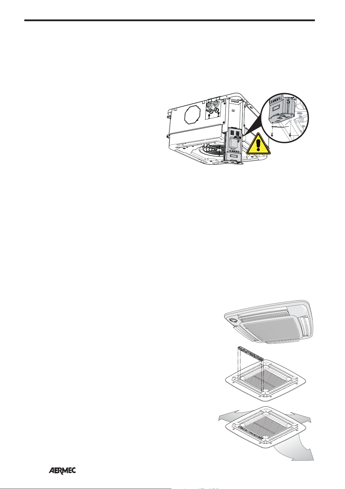
FAILURE OF THE THERMOSTAT FUSES AND REPLACEMENT
The installation and the electrical connections of the units and their
accessories must only be carried out
by people possessing the technical/
professional requisites for system
installation, transformation, extension
and maintenance, and who are able
to check these aspects for the purposes of safety and correct operation.
They will be generically referred to in
this manual as "Personnel with specific
technical skills". Check that the power
supply is disconnected before carrying
out any procedures on the unit.
If the fuses are burnt and for possible
replacement:
• Remove the delivery frame
• Extract the thermostat card
• Open the thermostat box
• Replace the faulty fuses
The fuses are 5 x 20 T series
(delayed) from 2 A to 10 A
• WARNING: for correct replacement,
the 2 A fuse must be inserted in location F3, while the 10 A fuse must be
inserted in F2, as shown in the image
below.
English
F3
ELECTRICAL CONNECTIONS WITH GLLI10N AND GLLI20N ACCESSORIES
Before installing the electric box, the
configuration of the electronic board
dip-switches needs to be checked in
order to adjust the board to the system.
Connect the VMF-E4 control panel,
supervision network cable, TTL
network cable, and probe and valve
cables based on system requirements.
For the connections, refer to the
wiring diagrams of the fan coil and
connected accessories.
GLLI10N
GLLI20N
L
N
230VAC
L
N
F2
VMF-SW1
CN3
230VAC
- L - N
> 650mm
AGLLI10/20NFJ 07/11_4528572_00
41

SCHEMI ELETTRICI • WIRING DIAGRAMS • SCHEMAS ELECTRIQUES • SCHALTPLÄNE • ESQUEMAS ELÉCTRICOS
LEGENDA • READING KEY • LEGENDE • LEGENDE • LEYENDA
Español
AL • Supply
= Alimentatore
Power supply
Alimentation electrique
Spannung
Alimentador
AMP=Contatto allarme pompa scarico
condensa
Contact alarm condensate pump
discharge
Contact d'alarme de décharge de
pompe condensat
Kontakt Alarm Kondensatpumpe
Entlastung
Contacto de alarma de bomba de
descarga de condensados
CE = Contatto esterno
CN = Connettore
Connector
Connecteur
Schütz
Conector
F = Fusibile • Fuse • Fusible
Sicherung • Fusible
IG = Interruttore generale
Main switch
Interupteur général
Hauptschalter
Interruptor general
M = Morsettiera
Terminal board
Boitier
Klemmleiste
Placa de bornes
Bomba de desagüe de condensado
MV = Motore ventilatore • Fan motor
Moteur ventilateur •
Ventilatormotor
Motor del ventilador
PE = Collegamento a terra
GND Earth connection
Mise à terre
Erdanschluss
Toma de tierra
SA = Sonda temperatura aria
Air temperature probe
Sonde temp. de l'air
Temperaturfühler
Sonda temperatura del aire
SW1 = Dip Switch
SW (CN2) = (SW4)
Sonda temperatura acqua
Water temperature probe
Sonde temp. eau
Wasserfühler
Sonda temperatura del agua
SW (CN3) = (VMF-SW1)
Sonda temperatura acqua (impianti 4 tubi)
Water temperature probe (4-pipe version)
Sonde temp. eau (systèmes à 4 tuyaux)
Wasserfühler (4-Leiter-Systemen)
Sonda temperatura del agua
(instalaciones de 4 tubos)
VHL =Valvola
Valve
Vanne
Ventil
Válvula
= Componenti non forniti
Components not supplied
Composants non fournis
Nicht lieferbare Teile
Componentes no suministrados
= Componenti forniti optional
Optional components
Composants en option
Optionsteile
Componentes opcionales
=Collegamenti da eseguire in loco
On-site wiring
Raccordements à effectuer in situ
Vor Ort auszuführende Anschlüsse
Cableado in situ
MP = Pompa scarico condensa
Condensate drain pump
Pompe de vidange du condensat
Kondensatablass Pumpe
AR = Arancio • Orange • Orange • Orange • Naranja
BI = Bianco • White • Blanc • Weiss • Blanco
BL = Blu • Blue • Bleu • Blau • Azul
GR = Grigio • Grey • Gris • Gray • Gris
MA = Marrone • Brown • Marron • Braun • Marrón
NE = Nero • Black • Noir • Schwarz • Negro
RO = Rosso • Red • Rouge • Rot • Rojo
ROS = Rosa • Pink • Rose • Rosa • Rosa
VE = Verde • Green • Vert • Grün • Verde
VI = Viola • Violet • Violet • Violet • Violeta
Gli schemi elettrici sono soggetti ad un continuo aggiornamento, è obbligatorio quindi fare riferimento a quelli a bordo macchina.
All wiring diagrams are constantly updated. Please refer to the ones supplied with the unit.
Nos schémas électriques étant constamment mis à jour, il faut absolument se référer à ceux fournis à bord de nos appareils.
Die Schaltpläne werden ständig aktualisiert, deswegen muss man sich stets auf das mit dem Gerät gelieferte Schaltschema beziehen.
El cableado de las máquinas es sometido a actualizaciones constantes. Por favor, para cada unidad hagan referencia a los esquemas suministrados con la misma.
96
AGLLI10/20NFJ 07/11_4528572_00

SCHEMI ELETTRICI • WIRING DIAGRAMS • SCHEMAS ELECTRIQUES • SCHALTPLÄNE • ESQUEMAS ELÉCTRICOS
FCLI
GLLI10N / GLLI20N
WMF-SW1
CN1
CN3
SW4
LED
SA
TX/RX
GND-TTL
MODE
5V
TX/RX
GND
TTL
M22
CN2
M26
CE
1
1
GND
2
2
CF
3
3
A
4
4
B
5
5
GND
6
6
M15
RS485
M14
M16
SW1
L17
M17
M18
M19
M20
M25
M21
JP1
RL1 RL2 RL3
M28
M27
+
C1
CLOSED FOR FCLI
RL4 RL5 RL6
Y2Y1
N
N1V3V2V1
MA
230V 50Hz
IG
NL
L
TR1
M3
RL7
F2 F3
BL
MA
PE
N
Español
F 10A F 4A
AUX/RE
LNN
1234
1234
GND
Signal Supply
INVERTER
Hall
-CBA+
E4
BI
BI
NE
NE
GR
181317
181317
GR
ROS
ROS
6
6
12
12
BL
BL
5
5
14
14
NE
11
11
VHL1
VHL20
VHL2
VHL22
NE
4
4
3
3
BL
10
10
VI
BL
5
5
2
2
MA
BL
MA
15
15
AR
1
1
6
6
NE
BI
BI
2
1
2
1
1
2
1
2
16
16
MA
BL
8
9
7
7
9
8
3
3
4
3
4
3
4
4
MP
VHL
BI
BL
2
55
44
VI
66
1
M
RO
AMP
11
33
2
RONE
GIBLVE
M
Out motor
MV
RST ONLAL V+ IN
Gli schemi elettrici sono soggetti ad un continuo aggiornamento, è obbligatorio quindi fare riferimento a quelli a bordo macchina.
All wiring diagrams are constantly updated. Please refer to the ones supplied with the unit.
Nos schémas électriques étant constamment mis à jour, il faut absolument se référer à ceux fournis à bord de nos appareils.
Die Schaltpläne werden ständig aktualisiert, deswegen muss man sich stets auf das mit dem Gerät gelieferte Schaltschema beziehen.
El cableado de las máquinas es sometido a actualizaciones constantes. Por favor, para cada unidad hagan referencia a los esquemas suministrados con la misma.
3
Dis. 5490480_03
AGLLI10/20NFJ 07/11_4528572_00
97

SCHEMI ELETTRICI • WIRING DIAGRAMS • SCHEMAS ELECTRIQUES • SCHALTPLÄNE • ESQUEMAS ELÉCTRICOS
FCLI
GLLI10N / GLLI20N
WMF-SW1
CN1
CN3
SW4
LED
SA
TX/RX
GND-TTL
MODE
5V
TX/RX
GND
TTL
M22
CN2
M26
CE
1
1
GND
2
2
CF
3
3
A
4
4
B
5
5
GND
6
6
M15
RS485
M14
M16
SW1
L17
M17
M18
M19
M20
M25
M21
JP1
RL1 RL2 RL3
M28
M27
+
C1
CLOSED FOR FCLI
RL4 RL5 RL6
N
230V 50Hz
IG
NL
L
TR1
M3
RL7
F2 F3
BL
MA
F 10A F 4A
MAY2Y1N1V3V2V1
AUX/RE
LNN
PE
N
1234
1234
GND
Signal Supply
INVERTER
Hall
-CBA+
E4
BI
BI
NE
NE
GR
181317
181317
GR
ROS
ROS
6
6
12
12
BL
BL
5
5
14
14
NE
BI
VI
11
11
NE
4
4
BL
5
10
10
BL
3
3
MA
AR
BL
15
15
5
16
6
6
16
7
7
8
9
9
8
VHL1
VHL20
VHL2
VHL22
NE
MA
1
2
1
2
BI
2
44
2
BL
VI
55
GIBLVE
BL
3
3
MP
1
66
3
3
M
RO
MA
4
4
4
4
33
RONE
BI
2
1
2
1
1
2
1
2
AMP
11
M
3
Dis. 5490481_03
Out motor
RST ONLAL V+ IN
MV
FCLI_VL
Gli schemi elettrici sono soggetti ad un continuo aggiornamento, è obbligatorio quindi fare riferimento a quelli a bordo macchina.
All wiring diagrams are constantly updated. Please refer to the ones supplied with the unit.
Nos schémas électriques étant constamment mis à jour, il faut absolument se référer à ceux fournis à bord de nos appareils.
Die Schaltpläne werden ständig aktualisiert, deswegen muss man sich stets auf das mit dem Gerät gelieferte Schaltschema beziehen.
El cableado de las máquinas es sometido a actualizaciones constantes. Por favor, para cada unidad hagan referencia a los esquemas suministrados con la misma.

AERMEC S.p.A.
I-37040 Bevilacqua (VR) - Italia
Via Roma, 996 - Tel. (+39) 0442 633111
Telefax (+39) 0442 93730 - (+39) 0442 93566
www .aermec. com
I dati tecnici riportati nella presente documentazione non sono impegnativi.
AERMEC S.p.A. si riserva la facoltà di apportare in qualsiasi momento tutte le modifiche ritenute necessarie per il miglioramento del prodotto.
Les données mentionnées dans ce manuel ne constituent aucun engagement de notre part. Aermec S.p.A. se réserve le droit de modifier à tous moments les
données considérées nécessaires à l’amelioration du produit.
Technical data shown in this booklet are not binding.
Aermec S.p.A. shall have the right to introduce at any time whatever modifications deemed necessary to the improvement of the product.
Im Sinne des technischen Fortsschrittes behält sich Aermec S.p.A. vor, in der Produktion Änderungen und Verbesserungen ohne Ankündigung durchzuführen.
ILos datos técnicos indicados en la presente documentación no son vinculantes.
Aermec S.p.A. se reserva el derecho de realizar en cualquier momento las modificaciones que estime necesarias para mejorar el producto.
 Loading...