

Page 1

AERCO XPC Gateway Communications
USER MANUAL
GF-122
OMM-0044_0C
AERCO XPC GATEWAY
Communications Manual
For Interfacing
AERCO Equipment
To
Building Automation Systems
Utilizing:
BACnet, N2, or LonWorks Protocol
Printed in U.S.A REVISED 11/10/2011
Page 2

GATEWAY COMMUNICATIONS MANUAL
The information contained in this manual is subject to
Telephone Support
Direct to AERCO Technical Support
(8 to 5 pm EST, Monday through Friday):
1-800-526-0288
AERCO International, Inc.
100 Oritani Dr.
Blauvelt, NY 10913
www.AERCO,com
© AERCO International, Inc., 2009
change without notice from AERCO International, Inc.
AERCO makes no warranty of any kind with respect to this
material, including but not limited to implied warranties of
merchantability and fitness for a particular application.
AERCO is not liable for errors appearing in this manual,
nor for incidental or consequential damages occurring in
connection with the furnishing, performance, or use of this
material.
2
Page 3

GF-122 AERCO XPC GATEWAY
Foreword
The AERCO XPC (Extended Protocol Converter) allows a Building Automation Systems (BAS) or
Energy Management System (EMS) utilizing BACnet, Johnson N2 or LonWorks protocol to
communicate with AERCO boilers and water heaters which utilize Modbus.
The AERCO XPC Gateway can monitor and control up to 300 points. Each XPC is individually
programmed to your specific needs.
The information provided in this document is divided into an Introduction followed by three (3) parts:
• Introduction – An introduction to and general description of the AERCO XPC Gateway.
• Part
• Part
• Part
I - Provides a top-level description of the AERCO XPC Gateway features and capabilities.
It also includes detailed set-up and programming instructions to interface the XPC
Gateway to the AERCO equipment to be monitored or controlled on the network.
II - Provides the set-up and programming instructions to interface the AERCO XPC
Gateway to a Building Automation System (BAS) or Energy Management System (EMS)
which utilizes BACnet, Johnson N2 or LonWorks protocol.
III – Provides the protocol mapping points for the standard configurations which can be
monitored or controlled.
PHRASES, ABBREVIATIONS & ACRONYMS
The phrases, abbreviations and acronyms used in this document are listed in the following table.
Phrases, Abbreviations and Acronyms
Phrase, Abbreviation
or Acronym
ARCnet Attached Resource Computer network. This is a Local Area Network (LAN)
similar to Ethernet.
ASCII American Standard Code for Information Interchange
ASHRAE American Society of Heating, Refrigerati ng and Air Conditioning Engineers
BACnet Building Automation and Control network. Protocol developed by ASHRAE.
BAS Building Automation System, often used interchangeably with EMS (see
below)
Baud Rate Symbol rate, or simply the number of distinct symbol changes (signaling
events) transmitted per second. It is not equal to bits per second, unless
each symbol is 1 bit long.
BCM Boiler Control Module used in a Modulex (MLX) Boil er
Meaning
BMS (BMS II) Boiler Management System (Boiler Management System II)
Bias Resistors A pair of resistors used to force the communi cation line to a definite logic
state so that noise is not picked up as invalid dat a during communication.
C-More Controller
(or Control Box)
DIP Dual In-Line Package
A control system developed by AERCO and currently used in all Benchmark
and KC Series product lines.
3
Page 4

GATEWAY COMMUNICATIONS MANUAL
EIA Electronic Industries Alliance
EIA-232
(or RS232)
EIA-485
(or RS485)
EMS Energy Management System
Ethernet A computer networking technology for Local Area Networks (LANs)
FDX Full-Duplex
HDX Half-Duplex
Hex Hexadecimal Number (0 - 9, A - F)
I/O Box Input/Output (I/O) Box currently used on al l B enchmark and KC Series
IP Internet Protocol
LonWorks A communication protocol developed by t he Echelon Corporation for control
LSB Least Significant Byte
MLX Modulex Boiler
Modbus® A serial, half-duplex data transmission protocol developed by AEG Modicon
MSB Most Significant Byte
A standard for serial, full-duplex (FDX) transmission of data based on the
EIA-232 Standard
A standard for serial, half-duplex (HDX) transmission of data based on the
EIA-485 Standard
products
applications
MS/TP Master-Slave/Token-Passing (usually over RS485 networks)
N2 A communications protocol developed by Johnson Controls
PTP Point-to-Point (usually over RS232 networks)
Response Time The maximum amount of time allowed to receive a response to a request
RS232
(or EIA-232)
RS422
(or EIA-422)
RS485
(or EIA-485)
RTU Remote Terminal Unit
SLTA Serial LonTalk Adapter
Terminating Resistor A resistor placed at each end of a daisy-chain or multi-dr op network in order
XPC Extended P rotocol Converter (manufactured by OEM Ctrl)
A standard for serial, full-duplex (FDX) transmission of data based on the
RS232 Standard
A standard for serial, full-duplex (FDX) transmission of data based on the
RS422 Standard
A standard for serial, half-duplex (HDX) transmission of data based on the
RS485 Standard
to prevent reflections that may cause invalid data in the communication
4
Page 5

GF-122 AERCO XPC GATEWAY
TABLE OF CONTENTS
SECTION 1 INTRODUCTION AND GENERAL DESCRIPTION ................................................ 10
1.1 INTRODUCTION ............................................................................................................................ 10
1.2 REFERENCE DOCUMENTS .......................................................................................................... 10
1.3 AERCO XPC GATEWAY PURPOSE AND USE .......................................................................... 10
1.4 AERCO XPC GATEWAY DESCRIPTION .................................................................................... 11
1.5 GATEWAY PORTS & JUMPERS .................................................................................................. 13
1.5.1 Port 1a ........................................................................................................................................................ 13
1.5.2 Port 2 .......................................................................................................................................................... 13
1.5.3 Local Access Port ...................................................................................................................................... 13
1.5.4 Optional Plug-In Module (Port 1b) ............................................................................................................ 13
1.5.5 Jumper Settings .......................................................................................................................................... 13
1.6 POWER INPUT, PROTOCOL SELECTION & GATEWAY ADDRESSING .............................. 16
1.6.1 Input Power Connection ............................................................................................................................ 16
1.6.2 Protocol and Baud Rate Select ................................................................................................................... 16
1.6.3 Gateway Address Switches ........................................................................................................................ 17
1.7 GATEWAY STATUS INDICATORS ............................................................................................. 17
1.8 BASIC GATEWAY OPERATION .................................................................................................. 19
1.9 XPC GATEWAY REFERENCE DATA .......................................................................................... 20
1.10 QUICK SETUP GUIDE ................................................................................................................. 21
1.10.1 Quick Setup Guide ................................................................................................................................... 22
1.10.2 BACNET MS/TP to AERCO XPC .......................................................................................................... 23
1.10.3 LON to AERCO XPC (with LON-OC) ................................................................................................... 24
1.10.4 LON to AERCO XPC (with SLTA) ........................................................................................................ 25
1.10.5 LON to XPC (with LON-OC) .................................................................................................................. 26
1.10.6 AERCO XPC to Boiler Management System (BMS) .............................................................................. 27
1.10.7 AERCO XPC to Boiler Management System II (BMS II) ...................................................................... 28
1.10.8 AERCO XPC to C-More ......................................................................................................................... 29
1.10.9 AERCO XPC to BCM (on MLX Boiler) ................................................................................................. 30
1.10.10 AERCO XPC to ECS (with Eurotherm Control) ................................................................................... 31
SECTION 2 INTERFACING THE XPC WITH C-MORE CONTROLLED UNITS ................... 34
2.1 INTRODUCTION ............................................................................................................................ 34
2.2 PHYSICAL NETWORK WIRING .................................................................................................. 34
2.3 C-MORE BOILERS OR HEATERS CONTROLLED BY BAS VIA THE GATEWAY ............... 34
2.4 C-MORE CONTROLLER MODBUS COMMUNICATION INTERFACE ................................... 35
2.5 RS485 LOOP TERMINATING RESISTORS AND BIAS .............................................................. 37
2.5.1 C-More Boiler Controller Terminating Resistor and Bias ......................................................................... 37
2.5.2 BAS Terminating Resistor and Bias .......................................................................................................... 41
2.6 C-MORE CONTROLLER WIRING CONNECTIONS TO AERCO XPC GATEWAY ................ 41
2.6.1 C-More Wiring C onnections to XPC Port 2 .............................................................................................. 41
2.6.2 C-More Wiring C onnections to XPC Port 1a ............................................................................................ 42
2.7 CONFIGURING THE C-MORE CONTROLLERS ........................................................................ 43
2.7.1 C-More Controller Monitoring and Configuration Control ....................................................................... 43
2.7.2 Direct Drive Control and Monitoring ........................................................................................................ 44
2.7.3 Remote Setpoint Control ............................................................................................................................ 44
SECTION 3 INTERFACING THE XPC TO BOILER MANAGEM ENT SYSTEMS .................. 47
3.1 INTRODUCTION ............................................................................................................................ 47
3.2 INTERFACING THE XPC GATEWAY TO BMS, MODEL 158 .................................................. 47
3.2.1 BMS Set-Up For Monitoring ..................................................................................................................... 48
3.2.2 C-More Boilers Being Network-Controlled by a BMS ............................................................................. 51
3.2.3 BMS Setup For Remote Setpoint Control From the XPC Gateway .......................................................... 53
3.3 INTERFACING THE XPC GATEWAY TO BMS II, MODEL 5R5-384 ....................................... 55
3.3.1 BMS II Set-Up For Monitoring ................................................................................................................. 56
5
Page 6

GATEWAY COMMUNICATIONS MANUAL
3.3.2 C-More Boilers Being Network-Controlled by a BMS II .......................................................................... 59
3.3.3 Modulex Boile rs Being Network-Controlled by a BMS II ........................................................................ 60
3.3.4 BMS II Setup For Remote Setpoint Control From The XPC Gateway ..................................................... 61
SECTION 4 AERCO XPC GATEWAY TO BCM CONTROLLED MODUL E X BOILERS .. 64
4.1 CONNECTION AND SET-UP OF BOILER COMMUNI CATIONS MODULES (BCMS) .......... 64
4.2 BCM WIRING CONNECTIONS TO AERCO XPC GATEWAY .................................................. 65
4.2.1 BCM Wiring Connections to XPC Port 2 .................................................................................................. 65
4.2.2 BCM Wiring Connections to XPC Port 1a ................................................................................................ 66
4.3 CONFIGURING THE BCM CONTROLLER ................................................................................. 67
SECTION 5 XPC GATEWAY TO ECS CONTROLLED HOT WATER HEATERS .................. 68
5.1 CONNECTION AND SET-UP OF ELECTRONIC CONTROL SYSTEM (ECS) ......................... 68
5.2 ECS WIRING CONNECTIONS TO AERCO XPC GATEWAY ................................................... 70
5.2.1 ECS Wiring Connec t ions to XPC Port 2 .................................................................................................... 70
5.2.2 ECS Wiring Connec t ions to XPC Port 1a .................................................................................................. 71
5.3 CONFIGURING THE ECS CONTROLLER .................................................................................. 72
5.4 CONFIGURING THE ECS CONTROLLER FOR REMOTE SETPOINT OPERATION ............. 72
SECTION 6 WHAT IS PART II OF THIS DOCUMENT ABOUT? .............................................. 74
SECTION 7 PROTOCOL OVERVIEW ............................................................................................ 74
7.1 WHAT IS A PROTOCOL? .............................................................................................................. 74
7.2 WHY ARE THERE SO MANY PROTOCOLS? ............................................................................. 74
7.3 WHY BUILD INTHE MOST WIDELY USED PROTOCOLS? .................................................... 75
7.4 WHAT DOES THE SITE INTEGRATOR NEED? ......................................................................... 75
SECTION 8 BACNET .......................................................................................................................... 76
SECTION 9 BACNET OVER ARC156 .............................................................................................. 76
9.1 CONFIGURING THE AERCO XPC FOR ARC156 ....................................................................... 76
SECTION 10 BACNET MS/TP ............................................................................................................. 78
10.1 CONFIGURING THE AERCO XPC FOR BACNET MS/TP ....................................................... 78
SECTION 11 BACNET PTP ................................................................................................................. 80
11.1 CONFIGURING THE AERCO XPC FOR BACNET PTP ........................................................... 80
SECTION 12 JOHNSON CONTROLS (N2) ....................................................................................... 82
12.1 CONFIGURING THE AERCO XPC FOR N2 F OR PORT 1A .................................................... 82
SECTION 13 LONWORKS ................................................................................................................... 84
13.1 CONFIGURING THE AERCO XPC FOR LONTALK VIA SLTA-10 ........................................ 84
13.2 CONFIGURING THE AERCO XPC FOR LONWORKS OPTION CARD ................................. 86
SECTION 14 TROUBLESHOOTING ................................................................................................. 88
14.1 MOST COMMON COMMUNICATION PROBLEMS ................................................................ 88
14.1.1 No Receive LED Indication ..................................................................................................................... 88
14.1.2 Wiring termination ................................................................................................................................... 88
14.1.3 Jumper selection ...................................................................................................................................... 88
14.1.4 Dipswitch selection .................................................................................................................................. 88
14.1.5 Addressing ............................................................................................................................................... 88
14.2 BACNET OVER ARC156 ............................................................................................................. 88
14.3 BACNET MS/TP ............................................................................................................................ 89
14.4 BACNET PTP ................................................................................................................................. 90
14.5 N2 ................................................................................................................................................... 90
14.6 LONWORKS .................................................................................................................................. 91
14.7 COMMISSIONING THE XPC FOR LONWORKS ...................................................................... 91
14.8 COMMUNICATION LED'S .......................................................................................................... 92
SECTION 15 COMPLIANCE ............................................................................................................... 94
15.1 FCC COMPLIANCE ...................................................................................................................... 94
15.2 BACNET COMPLIANCE ............................................................................................................. 94
SECTION 16 BACNET PROTOCOL IMPLEMENTATION CONFORMANCE STATEMENT 94
16.1 ANALOG VALUE (PAR) .............................................................................................................. 96
16.2 BINARY VALUE (PAR), (CLOCK), AND (STAT) ..................................................................... 97
16.2.1 notification_class .................................................................................................................................. 98
6
Page 7

GF-122 AERCO XPC GATEWAY
16.2.2 notify_type ............................................................................................................................................. 98
16.2.3 out_of_service ...................................................................................................................................... 98
16.2.4 present_value ....................................................................................................................................... 98
16.2.5 relinquish_default ................................................................................................................................. 98
16.2.6 time_delay ............................................................................................................................................. 98
16.3 ANALOG VALUE (STAT) ........................................................................................................... 99
16.4 BINARY VALUE (PAR), (CLOCK), AND (STAT) ................................................................... 101
16.5 BINARY VALUE (MODULE ALARM) .................................................................................... 102
16.6 CALENDAR ................................................................................................................................. 103
16.7 DEVICE ........................................................................................................................................ 103
16.8 FILE .............................................................................................................................................. 105
16.9 MULTI_STATE VALUE ............................................................................................................. 105
16.10 MULTI_STATE VALUE (STAT) ............................................................................................. 106
16.11 NOTIFICATION CLASS ........................................................................................................... 107
16.12 PROGRAM ................................................................................................................................. 107
16.13 SCHEDULE ................................................................................................................................ 108
16.14 TREND_LOG (NON-BACNET PROPERTY) .......................................................................... 109
SECTION 17 BACNET DATA LINK LAYER OPTIONS ............................................................... 110
SECTION 18 CONFORMANCE STATEMENT FOR MODBUS IMPL EMENTATION ........... 111
SECTION 19 CONFORMANCE STATEMENT FOR JOHNSON N2 IMPLEMENTATION .... 113
SECTION 20 CONFORMANCE STATEMENT FOR LONWORKS IMPLEMENTATION ..... 116
SECTION 21 INTRODUCTION to Part III ...................................................................................... 120
SECTION 22 APPLOADER SOFTWARE UTILITY ...................................................................... 120
SECTION 23 PROGRAM FILES AND FILENAMES ..................................................................... 120
SECTION 24 CONTROL POINTS AND SPEED OF OPERATION ............................................. 121
SECTION 25 MODBUS TIMERS ...................................................................................................... 121
SECTION 26 MODBUS RESPONSE TIME ..................................................................................... 122
SECTION 27 MODBUS INTERPACKET Delay .............................................................................. 122
SECTION 28 AERCO EQUIPMENT MONITOR & CONTROL POINT DEFINITIONS ......... 123
SECTION 29 PROTOCOL MAPPING TABLES ............................................................................. 129
SECTION 30 C-MORE BOILER CONTROLLER STATUS & FAULT MESSAGES ................ 185
SECTION 31 ERROR CODES ........................................................................................................... 188
7
Page 8

GATEWAY COMMUNICATIONS MANUAL
THIS PAGE INTENTIONALLY BLANK
8
Page 9

GF-122 AERCO XPC GATEWAY
INTRODUCTION
AERCO XPC DESCRIPTION
QUICK SETUP GUIDE
And
9
Page 10

GATEWAY COMMUNICATIONS MANUAL
DOCUMENT
TITLE
AERCO
(www.aerco.com)
GF-108M,
Boiler Management System (BMS or BMS II)
GF-112
C-More Control Panel Operation Manual
GF-114
Modbus Communication Manual
GF-115-C
Operation & Wiring Guides for Modulex E8
Eurotherm
(www.eurotherm.com/controllers/2400_doc.htm)
HA026230
2000 Series Communication Handbook
SECTION 1 INTRODUCTION AND GENERAL DESCRIPTION
1.1 INTRODUCTION
AERCO Boilers and Water Heaters equipped with any of the AERCO Control Systems listed below
can communicate directly with a Building Automation System (BAS) or Energy Management System
(EMS) utilizing Modbus RTU protocol. The AERCO Control Systems include:
• C-More Control System
• Boiler Management System (BMS or BMS II)
• Boiler Communications Module (BCM)
• Electronic Control System (ECS)
Although most BAS and EMS Systems support Modbus communication, many installations may
already be utilizing different types of communication protocol. In addition to Modbus, the most
commonly used protocols are BACnet, LonWorks and N2. In order to bridge the gap between
Modbus and other popular protocols, AERCO has developed the AERCO XPC Communications
Gateway. This Gateway makes connectivity to AERCO equipment as simple as “plug-and-play”.
The remaining sections in Part I provide top level descriptions of the AERCO Gateway and how it can
be implemented to provide connectivity between AERCO equipment and a BAS or EMS system
utilizing Modbus or other popular communication protocols.
Sections 2 through 5 provide detailed information and procedures for implementing network set-ups
to interface the XPC Gateway to AERCO boilers and water heaters.
1.2 REFERENCE DOCUMENTS
References to the following documents are included in the appropriate sections and subsections of
this manual:
AC-105 Electronic Control System
Installation, Operation & Maintenance Manual
GF-124
HA025132 2404/2408 Control Setpoint Programmer Installation
Installation, Operation & Maintenance Manual
Controller & Boiler Communications Module (BCM)
and Operation Handbook
1.3 AERCO XPC GATEWAY PURPOSE AND USE
The primary purpos e of the AERCO XPC Gateway is to allow monitoring or control of AERCO units.
Due to the operational nature of the Gateway, it should not be used to configure the system.
Configuration (or setup information) should not be constantly changed since this information is
generally stored in EEPROM non-volatile memory in the AERCO Controllers (C-More, BMS, and
10
Page 11

GF-122 AERCO XPC GATEWAY
ECS). This type of memory can be read as often as needed, however, it has a limited number of
write cycles.
The Gateway is preprogrammed with standard monitor and control points. These standard points are
those most often requested by AERCO customers (see Part III). If different or additional points are
required for a particular system, custom factory programming is available. There are five (5) standard
pre-programmed configurations to choose from:
• Programmed for 4 C-More controlled boilers and 1 Boiler Management System (BMS/BMS II)
• Programmed for 1 BMS/BMS II and 8 C-More controlled boilers
• Programmed for 1 BMS/BMS II and 12 C-More controlled boilers
• Programming for 1 BMS II and 4 BCM controlled Modulex boilers
• Programmed for 4 ECS controlled water heaters
Multiple XPC Gateways can be used in certain situations.
If necessary, the XPC Gateway can accept up to 300 monitor and control points. Network points and
unit addresses are pre-programmed in the Gateway. In addition, all of the supported protocols –
BACNET, LonWorks, and N2 are preprogrammed for all points. They can be easily selected using
the DIP switches provided on the Gateway.
1.4 AERCO XPC GATEWAY DESCRIPTION
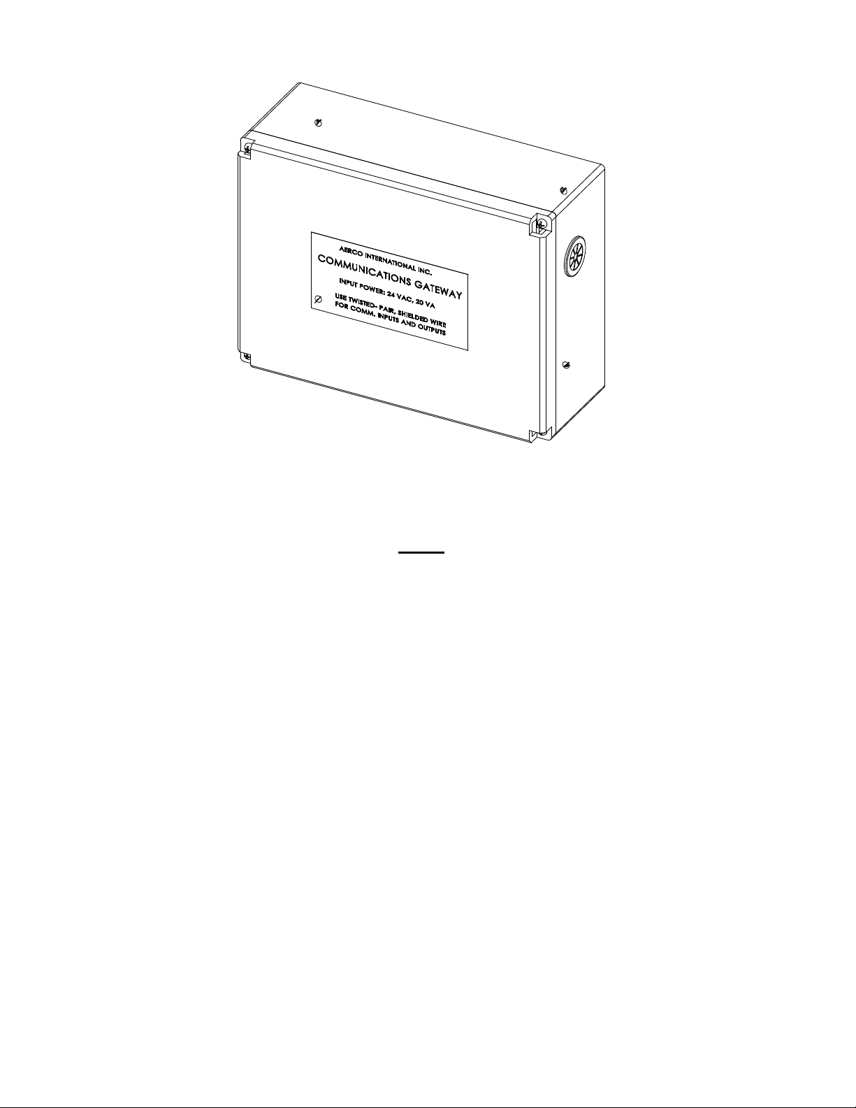
The XPC Gateway Controller is shown in Figure 1-1. The Gateway is housed i n a compact enclosure
measuring approximately 6” H x 8” W x 3” D as shown in Figure 1-2. The installed location of the
Gateway will depend on the types of AERCO equipment being used with the Gateway.
Figure 1-1. AERCO XPC Gateway
11
Page 12
GATEWAY COMMUNICATIONS MANUAL
Figure 1-2. AERCO XPC Gateway Installed in Enclosure
NOTE
If desired, the Gateway can always be wall-mounted, regardless of the
types of AERCO equipment being used. However, signaling wire
lengths must not exceed 50 feet for RS232 and 3000 feet for RS485
networks.
• Benchmark Series Boilers: XPC Gateway can be installed behind the front panel door of the
Benchmark below the Input/Output (I/O) Box.
• KC1000 Series Boilers or Heaters: XPC Gateway can be installed on the left side of the unit
above the Input/Output (I/O) Box.
• Boiler Management System (BMS/BMS II): XPC Gateway is normally mounted on a wall in
close proximity to the BMS.
• Indirect-Fired Heaters with ECS Control System: Gateway is normally wall-mounted.
• Modulex Boilers equipped with Boiler Control Modules (BCMs).
The Gateway is powered by 24 VAC, 50/60 Hz, single-phase, 20 VAC. Power and Input/Output
(I/O) signal connections are made via four grommetted cutouts (one on each side and two on
the bottom surface of the Gateway enclosure. I/O signal wiring is routed through the left-side and
bottom-left cutouts of the Gateway enclosure. Connection to the Lon module is accomplished via
the bottom-right cutout. Input power wiring (24 VAC, 50/60 Hz) and earth ground wire is routed
through the right-side cutout of the enclosure to minimize noise on the signal wiring.
12
Page 13

GF-122 AERCO XPC GATEWAY
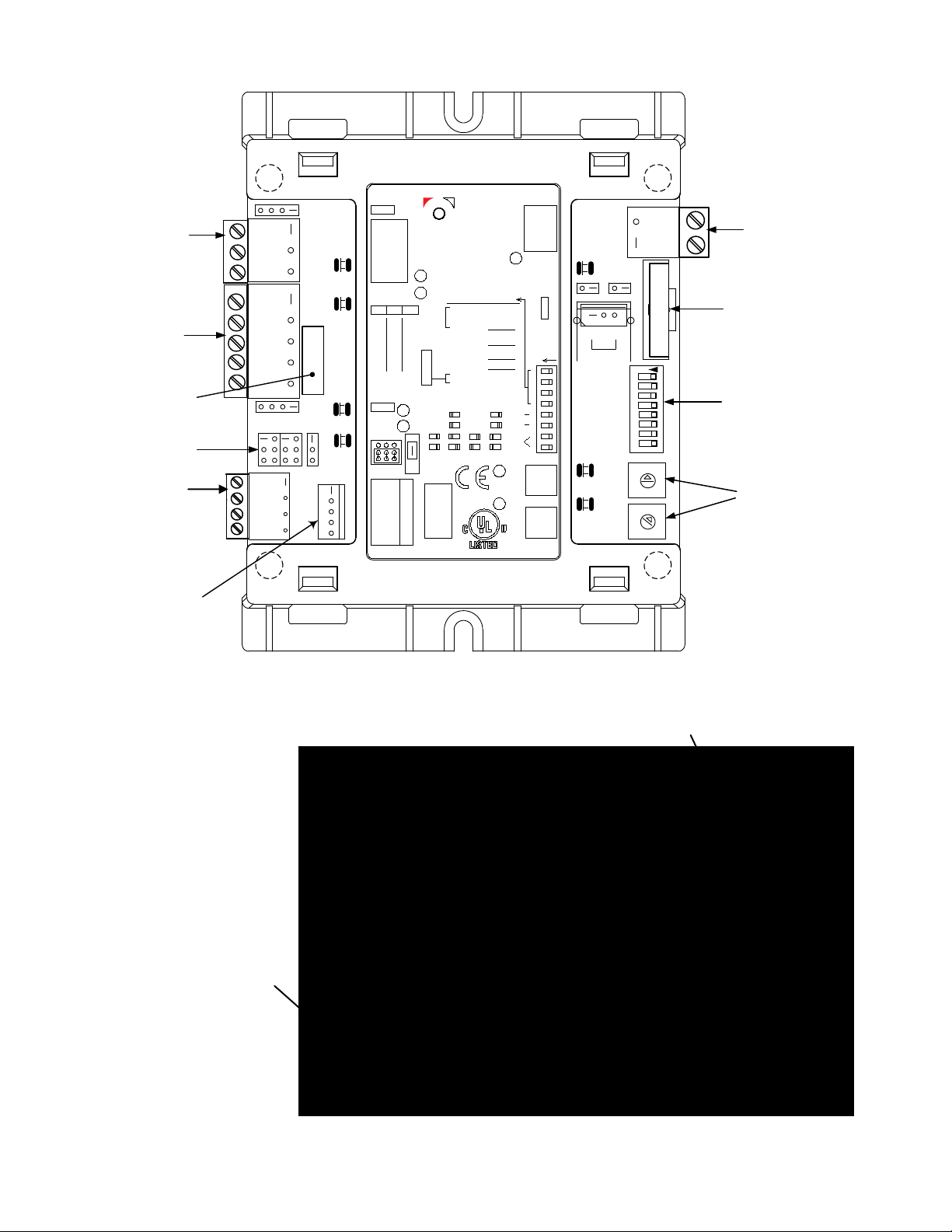
1.5 GATEWAY PORTS & JUMPERS
The Gateway Input/Output (I/O) signal ports are located on the left side of the XPC Gateway, behind
the enclosure cover as illustrated in Figure 1-3. In addition, jumpers are also provided on the left side
of the Gateway to select the physical type of network being utilized on port 2. The following
subsections provide brief descriptions of the ports and jumpers provided.
1.5.1 Port 1a
Port 1a (Figure 1-3, Detail “A”) can only be configured for RS485 communication or special ARC156.
This port is normally used for BAS connections. However, if the BAS is communicating via BACnet
PTP or is connected to a LonWorks SLTA module, Port 1a cannot be used. Refer to the AERCO XPC
Gateway Integration Guide included as Part II of this manual.
1.5.2 Port 2
Port 2 (Figure 1-3, Detail “B”) can be configured for RS485 or RS232 communication. This port
normally connects to AERCO equipment except when the BAS is utilizing BACnet PTP or a
LonWorks SLTA. In this case, Port 1a must be used for the AERCO equipment. The jumpers located
below Port 2 are used to select RS485 or RS232 (EIA-485 or EIA-232) communication and either a 2wire or 4-wire communication interface (see para. 1.5.5).
1.5.3 Local Access Port
The Local Access Port (Figure 1-3, Detail “C2”) is used to program or read Gateway setup
information or to monitor network traffic from the Gateway with a PC using a special interface module.
Special network display monitors can also be connected to this port to display network information.
1.5.4 Optional Plug-In Module (Port 1b)
A 14-pin connector labeled Port 1b is for an optional plug-in module. Currently, there is a LonWorks
transceiver module that allows LonWorks FTT10A communication without the use of a Serial Lon
Talk Adapter (SLTA).
1.5.5 Jumper Settings
Two jumpers are located side-by-side below PORT 2 on the Gateway (Figure 1-3, Detail “D”). These
jumpers provide the following functions:
• EIA-232/EIA-485 Jumper
connector to select either an EIA-485 (RS485) or EIA-232 (RS232) connection to the
BAS. Setting the jumper to the lower position selects EIA-485 (RS485) which is the
default position. Setting the jumper to the upper position selects EIA-232 (RS232).
• 2-Wire/4-Wire Jumper
connector. Setting the jumper to the upper position selects 2-wire communication. Setting
the jumper to the lower position selects 4-wire communication.
- This jumper is connected across 8 of the 12 pins of the header
– This jumper is connected across 2 of the 3 pins of the header
13
Page 14
GATEWAY COMMUNICATIONS MANUAL
+12V
RNET-
RNET+
GND
COM
NET-
RX
TX
FORMAT
POWER
NET+
CMNET
ONE's
ERR
RUN
OPTIONS
TEN's
BATT
24VAC
GND
POWER
485
232
LN-
/S
+12
GND
LN+
2W
RX
TX
4W
BT485
Net +
Net -
Shield
Port 1a
Tx1
Rx1
Port 1b
Port 2
4w
2w
Gnd
+12V
Gnd
Rnet+
Sense
Rnet +
Rnet -
R n e t
Rnet+12V
Local
Access
10's
1's
0
134
5
2
78
9 6
0
134
5
2
78
9 6
4
3
2
1
On
5
6
7
8
Run
Error
Power
Format
Gnd
Hot
EIA-232
EIA-485
Baud
EIA485
19.2k
38.4k 76.8k
BMS
Port 2
ARC156
Port 1
9600
BMS
Switches
(0 = off, 1 = on)
MSTP (m)
MSTP (s)
PTP
8 7 6 5
Protocol
0 0 0 0
0 0 0 1
0 0 1 0
BACnet
BMS
Port 1
TYPE: 002106
Enclosed Energy Management Equipment
Made in USA
®
24V ac
2w 4w
Tx+
n/c
n/c
Net+
Rx+
Rx-
Tx-Net-
232
Tx
DTR
DCD
Rx
Signal Ground
+
-
Batt
CR
2032
BT485
Lon SLTA
1 1 0 1
Lon PlugIn
Ethernet
1 1 1 1
1 1 1 0
N2
Modbus
®
®
0 1 1
0 1 0 0
0
Tx2
Rx2
E143900
88FO
R
Class 2, 24Vac
Conductors Only
Use Copper
50-60Hz, 10VA, 0.42A
®
XPC
PORT 1a
( DETAIL “A”)
PORT 2
( DETAIL “B”)
RNET
(
DETAIL “C1”)
PORT 1b
JUMPERS
( DETAIL “D”)
0
5
1
2
3
4
6
7
8
9
0
5
1
2
3
4
6
7
8
9
8
7
6
5
4
32
1
ON
INPUT
POWER
( 24 VAC)
DIP
SWITCHES
( DETAIL “E”)
ADDRESS
SELECT
SWITCHES
( DETAIL “F”)
BATTERY
(3V)
LOCAL
ACCESS
PORT
(DETAIL “C2”)
NOTE: Ground
(see Sht 2 of 3).
RNET
(DETAIL “C1”)
Ground connection lug for
Earth ground connection lug. Connect
is attached to
Mounting Panel
Figure 1-3. XPC Gateway Ports, Jumpers and Switches (Sheet 1 of 3)
RNET connector. DO NOT
REMOVE. This ground
MUST be connected when
power is applied to the
Gateway Controller.
Figure 1-3. XPC Gateway Chassis Ground Locations (Sheet 2 of 3)
earth ground here.
14
Page 15
8
7
6
5
4
32
1
ON
0
5
1
2
3
4
6
7
8
9
0
5
1
2
3
4
6
7
8
9
10's
1's
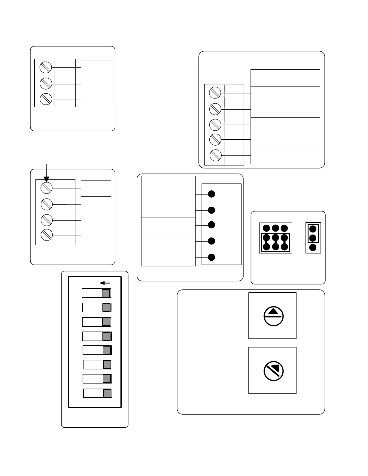
DETAIL F
DETAIL E
EIA-485
EIA-232
2W
4W
DETAIL D
Tx +
Port 2
DETAIL B
2W
4W
232
Net+
Tx
Net -
Tx -
Rx
N/C
Rx +
DTR
N/C
Rx -
DCD
SIGNAL
GROUND
Net +
Net -
Shield
PORT 1a
DETAIL A
RNET
Gnd
Rnet +
Rnet -
+12V
DETAIL C1
Local
Access
Gnd
Rnet +
Rnet -
+12V
Sense
DETAIL C2
Port 2
2W
4W
232
Local Access
RNET
Port 1a
Net +
DETAIL B
This BCD switch
of the address.
This BCD switch
the address.
This BCD switch
the address.
Note for all Pinout
NOTE: This ground must be
Net -
Shield
attached to Mounting Panel
(see Figure 1-3, Sht 2 of 3).
Images:
All connectors on
this page are
shown in the same
orientation as
shown on the
referenced PCB
illustration in
Figure1-3, Sheet 1
of 3.
GF-122 AERCO XPC GATEWAY
Net+ Tx+ Tx
Net- Tx- Rx
N/C Rx+ DTR
N/C Rx- DCD
Signal Ground
Gnd
Rnet +
Rnet -
+12V
Rnet +
Sense
Gnd
Rnet -
+12V
determines the
determines the
10 decimal
10 decimal
position (10, 20,
position (10, 20,
30, 40, etc.) of
30, 40, etc.) of
determines the 1
decimal position
(1, 2, 3, 4, etc.)
10’s
1’s
Figure 1-3. XPC Gateway Ports, Jumpers and Switches (Sheet 3 of 3)
15
Page 16

GATEWAY COMMUNICATIONS MANUAL
BAUD Rate
DIP Switch 1
DIP Switch 2
9600
OFF
OFF
19.2 K
OFF
ON
38.4 K
ON
OFF
76.8 K
ON
ON
1.6 POWER INPUT, PROTOCOL SELECTION & GATEWAY ADDRESSING
The Gateway input power connections, protocol selection, and Gateway addressing are
accomplished utilizing the connector and switches on the right side of the XPC Gateway as shown in
Figure 1-3. The following subsections provide brief descriptions of the ports and jumpers provided.
IMPORTANT
It is imperative that the XPC Gateway be powered by an isolated 24
VAC power supply which is dedicated only for use by the XPC
Gateway. Failure to observe this precaution will result in improper
Gateway operation.
1.6.1 Input Power Connection
The Gateway is powered by 24 VAC (Class 2), 50/60 Hz, 20 VA. The input power connector is
located on the upper right side of the Gateway (Figure 1-3, Sheet 1 of 3).
When connecting the power source, an earth ground MUST be connected to the ground screw on the
mounting panel. See Figure 1-3, Sheet 2 of 3.
In addition, a 3 volt lithium battery (CR2032) is installed below the AC power connector. This battery
is used to retain the current monitoring/control data stored in volatile memory.
WARNING
Do not remove the battery when the power is off. Doing so may erase
some recorded data as well as programming, especially on older
models not utilizing non-volatile memory. The battery maintains the
integrity of the data and coding contained in memory whenever the
supply voltage is not present.
1.6.2 Protocol and Baud Rate Select
Protocol and baud rate selection are accomplished using the 8 DIP switches shown in Figure 1-3,
Detail “E”. The DIP switches can be set to the ON (left) or OFF (right) position. The functions and
settings for each of these switches are listed in the Tables 1 and 2 which follow.
Table 1 Baud Rate Select Switches
• DIP Switch 3 selects whether XPC Port 1 or Port 2 will be connected to the BAS used with the
• DIP Switch 4 will normally be set to ON for RS485 communication. It should only be set to OFF if
Gateway. When DIP Switch 3 is OFF, Port 1 is connected to the BAS. When set to ON, Port 2 is
connected to the BAS. The other port will be used for connection of AERCO equipment.
the BAS Port is 1 and the BAS is communicating BACnet using the ARC156 method.
16
Page 17

GF-122 AERCO XPC GATEWAY
DIP Switch Settings
Protocol
8 7 6
5
Comments
BACnet
RS485 communication to BACnet
BACnet
BACnet
RS232 communication to BACnet
Johnson
RS485 communication to Johnson N2
Modbus
DO NOT USE FOR THIS
LonWorks
Serial LonTalk Adapter required.
LonWorks
Lon Option Card required
Table 2 Building Automation System (BAS) Protocol
MS/TP
Master
MS/TP
Slave
PTP
N2
SLTA
FTT10a
OFF OFF OFF OFF
OFF OFF OFF ON
OFF OFF ON OFF
OFF OFF ON ON
OFF ON OFF OFF
ON ON OFF ON
ON ON ON OFF
1.6.3 Gateway Address Switches
Master
DO NOT USE FOR THIS
APPLICATION
Master
Master
APPLICATION
(currently available from Echelon)
The Gateway contains two rotary address switches labeled 0 - 9 as shown in Figure 1-3, Detail “F”.
The upper switch is labeled “10’s” and the lower switch is labeled “1’s”. When multiple Gateways are
used and controlled by a single BAS/EMS, each Gateway must have its own unique address. Do not
set both the “10’s” and the “1’s” address switches to “0”. Doing so will disable the Gateway on the
network.
1.7 GATEWAY STATUS INDICATORS
In addition to the ports and switches described in the previous subsections, the XPC Gateway
contains seven (7) LED Status Indicators which can be monitored during Gateway operation. These
LED Status Indicators are illustrated and described in Figure 1-4 and Table 3.
17
Page 18

GATEWAY COMMUNICATIONS MANUAL
+12V
RNET-
RNET+
GND
COM
NET-
RX
TX
FORMAT
POWER
NET+
CMNET
ONE's
ERR
RUN
OPTIONS
TEN's
BATT
24VAC
AGND
POWER
RNET
485
232
LOCAL ACCESS
LN-
/S
+12
GND
LN+
2W
RX
TX
4W
BT485
Net +
Net -
Shield
Port 1a
Tx1
Rx1
Port 1b
Port 2
4w
2w
Gnd
+12V
Gnd
Rnet+
Sense
Rnet +
Rnet -
R n e t
Rnet+12V
Local
Access
10's
1's
0
134
5
2
78
9 6
0
134
5
2
78
9 6
4
3
2
1
On
5
6
7
8
Run
Error
Power
Format
Gnd
Hot
EIA-232
EIA-485
Baud
EIA485
19.2k 38.4k 76.8k
BMS
Port 2
ARC156
Port 1
9600
BMS
Switches
(0 = off, 1 = on)
MSTP (m)
MSTP (s)
PTP
8 7 6 5
Protocol
0 0 0 0
0 0 0 1
0 0 1 0
BACnet
BMS
Port 1
TYPE: 002106
Enclosed Energy Management Equipment
Made in USA
®
24V ac
2w
4w
Tx+
n/c
n/c
Net+
Rx+
Rx-
Tx-Net-
232
Tx
DTR
DCD
Rx
Signal Ground
+
-
Batt
CR
2032
BT485
Lon SLTA
1 1 0 1
Lon PlugIn
Ethernet
1 1 1 1
1 1 1 0
N2
Modbus
®
®
0
1 1
0 1 0 0
0
Tx2
Rx2
E143900
88FO
R
Class 2, 24Vac
Conductors Only
Use Copper
50-60Hz, 10VA, 0.42A
®
XPC
POWER
LED
RUN
LED
ERROR
LED
TX1
LED
RX1
LED
TX2
LED
RX2
LED
RNET
LOCAL
ACCESS
PORT
LED STATUS
TX1
Green LED flashes when data is being transmitted from
RX1
Green LED flashes when data is being received by the
Green LED lights when 24 VAC power is being supplied
RUN
Green LED lights to show Gateway status as described
TX2
Green LED flashes when data is being transmitted to
RX2
Green LED flashes when data is being received from
Figure 1-4. XPC Gateway Status LED Locations
INDICATOR
(LED1)
(LED2)`
POWER
(LED3)
(LED4)
ERROR
(LED5)
(LED6)
(LED7)
Table 3 Gateway LED Status Indicators
the BAS connected to Port 1.
BAS connected to Port 1.
to the Gateway.
in Table 4.
Red LED lights to show Gateway status as described in
Table 4.
the AERCO equipment connected to Port 2.
the AERCO equipment connected to Port 2.
FUNCTION
18
Page 19

If RUN LED Shows:
And ERROR LED Shows:
Status is:
2 flashes per second
Off
Normal
2 flashes per second
2 flashes,
Five minute auto-restart delay
2 flashes per second
3 flashes,
Gateway has just been
2 flashes per second
4 flashes,
Two or more devices on the
2 flashes per second
On
Exec halted after frequent
See also Part II “Communication LED’s”.
Table 4 RUN & ERROR LED Status
GF-122 AERCO XPC GATEWAY
alternating with RUN LED
then Off
then pause
after system error
formatted
network have the same
ARC156 network address
system errors or control
program halted
1.8 BASIC GATEWAY OPERATION
The Gateway scans the points list from top to bottom in a round-robin fashion. It will continually
retrieve the information from the programmed Modbus address and hold it for the BAS to read. The
information is therefore not real-ti me. How current the information is will depend on how quickly the
Gateway can scan all of the required pre-programmed points.
Information is updated based on the update time and priority of the information. If a point is not
updated within the allotted update time because the Gateway was not able to read it in time, the value
of that point will default to its programmed default value (usually zero).
To speed up the update rate of points and prevent dropouts (going to default value), communication
to any unused points can be disabled. This prevents the Gateway from waiting the full Response
Time programmed before moving to the next point, thereby reducing the scan cycle time interval.
19
Page 20

GATEWAY COMMUNICATIONS MANUAL
5-pin port supports EIA-232, EIA-485 2-wire or 4-wire
1.9 XPC GATEWAY REFERENCE DATA
The functional, physical and environmental specifications for the Gateway are listed in Table 5.
Table 5 AERCO XPC Gateway Specifications
Specification Description
Maximum number of points 300
Power 24 VAC ±10%, 50-60 Hz, 20 VA power consumption, Class 2
source only, 100 VA or less
Port 1a 3-pin port supports EIA-485 (RS485) 2-wire communication.
Protocols supported:
• BACnet over ARC156
• BACnet MS/TP
• Modbus (RTU/ASCII)
• Johnson N2
This port can be configured as a device port or a BAS port
NOTE: Port 1a or Port 1b can be used, but not both.
Port 1b 14-pin communication port supports plug-in cards such as
LonWorks or future Ethernet.
Port 2
Rnet Port
Local Access Port For local communication with a laptop computer running
Memory 1 MB non-volatile battery-backed RAM, 1 MB Flash memory,
communications.
Protocols supported:
• EIA-232 BACnet PTP, Modbus (RTU/ASCII), LonWorks
SLTA
• EIA-485 2-wire BACnet MS/TP, Modbus (RTU/ASCII),
Johnson N2
• EIA-485 4-wire BACnet MS/TP, Modbus (RTU/ASCII)
This port can be configured as a device port or BAS port.
4-pin port supports up to four RS Standard sensors and one
RS Plus, RS Pro, or RS Pro-F sensor for averaging or
high/low select control.
WebCTRL or AppLoader.
16-bit memory bus
20
Page 21

GF-122 AERCO XPC GATEWAY
Width
4 in. (102mm)
Height
5 in. (127mm)
Depth
1.75 in. (51mm)
Add for the LonWorks Card:
Width
1.8 in. (45.72mm)
Height
3.25 in. (82.55mm)
Depth
1.5 in. (38.1mm)
Distance apart cannot exceed ribbon cable:
9.75 in. (247.65 mm)
Width
2 in. (51 mm)
Height
4.8 in. (122mm)
LonWorks Option Card
1.325 in. (33.66 mm) apart – top 2 holes
.475 in. (12.07 mm) from edge
.890 in. (22.61 mm) bottom hole – from edge
Width
8.94 in. (227 mm) apart – top 2 & bottom 2 holes
Height
5.00 in. (127 mm) between top 2 & bottom 2 holes
Table 6 XPC Gateway Specifications - Continued
Specification Description
Battery 10-year Lithium CR2032 battery provides a minimum of 10,000
hours of data retention during power outages
Protection Built-in surge and transient protection circuitry - internal solid
state Polyswitches on the incoming power and network
connections.
Status Indicators LED's indicate status of communications, running, errors, and
power.
Environmental operating
range
-40° to 150°F (-40° to 65.6°C), 10–95% relative humidity, noncondensing
Overall dimensions
(without enclosure)
Mounting hole dimensions
(without enclosure)
Mounting hole dimensions
in enclosure
Rommended panel depth 1.75 in. (51mm)
Weight 9 oz.
BACnet support Conforms to the Advanced Application Controller (B-AAC)
Standard Device Profile as defined in ANSI/ASHRAE Standard
135-2004 (BACnet) Annex L
Listed by UL-916 (PAZX), cUL-916 (PAZX7), FCC Part 15-Subpart B-
Class A, CE EN50082-1997
1.10 QUICK SETUP GUIDE
A Quick Setup Guide is provided as additional guidance to configuring and integrating the AERCO
XPC Communications Gateway. The guide now follows.
21
Page 22
GATEWAY COMMUNICATIONS MANUAL
AERCO XPC QUICK SETUP GUIDE
Follow the instructions below to quickly wire and set up the AERCO XPC between your
Building Automation System (BAS) and AERCO equipment - Boiler Management System
(BMS/BMSII), Boiler Controls (C-MORE on Benchmark or KC1000 boilers or Boiler Control
Module (BCM) on Modulex (MLX) boilers), or Electronic Control System (ECS).
Select the 2 pages that apply to your configuration – one from pages 2 to 5 which outlines the
wiring and set up between your BAS and the AERCO XPC, and the other from pages 6 to
10 which outlines the wiring and set up between the AER CO X PC and AERCO equipment.
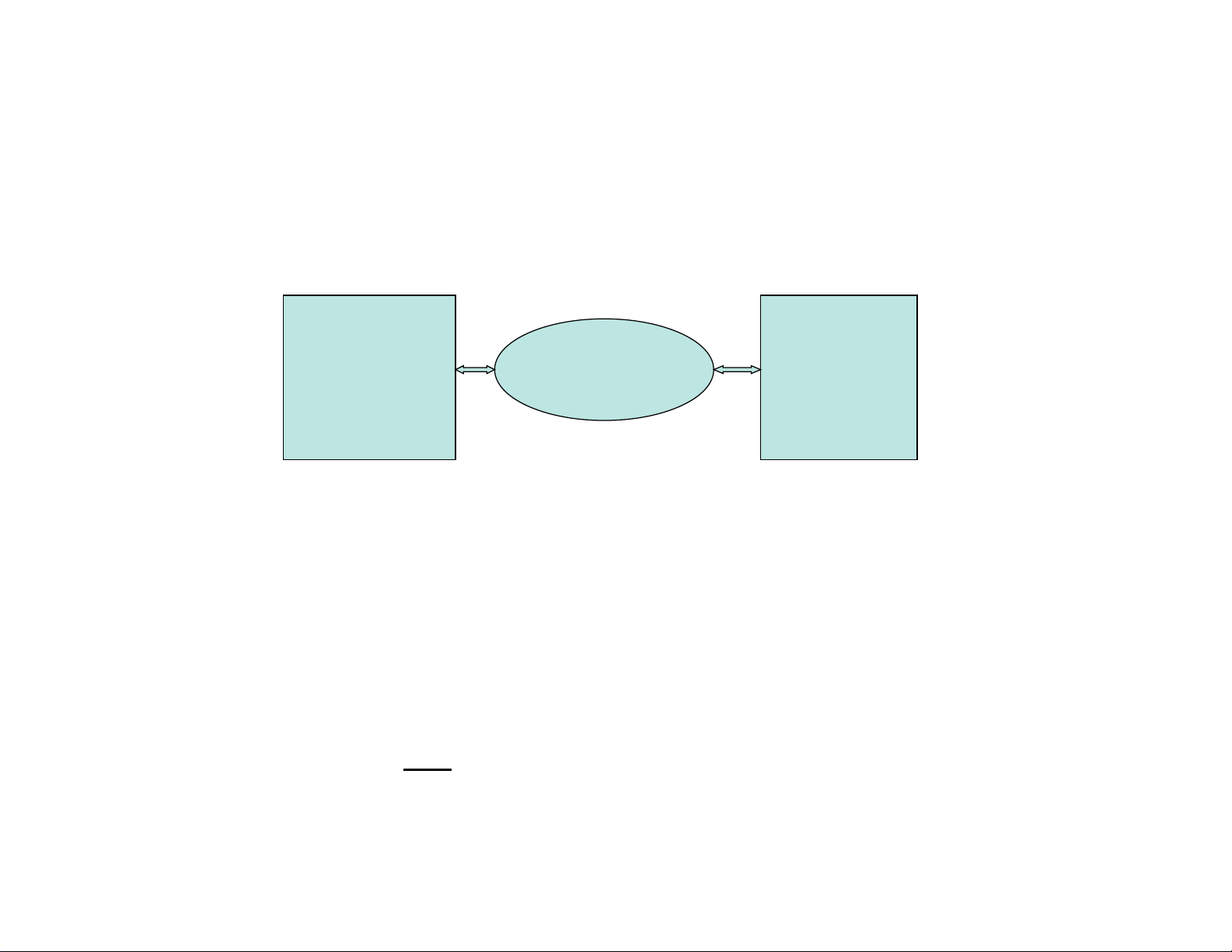
Note: The AERCO XPC cannot share power with other equipment. It must have its own
dedicated 24VAC supply else communication dropouts could result.
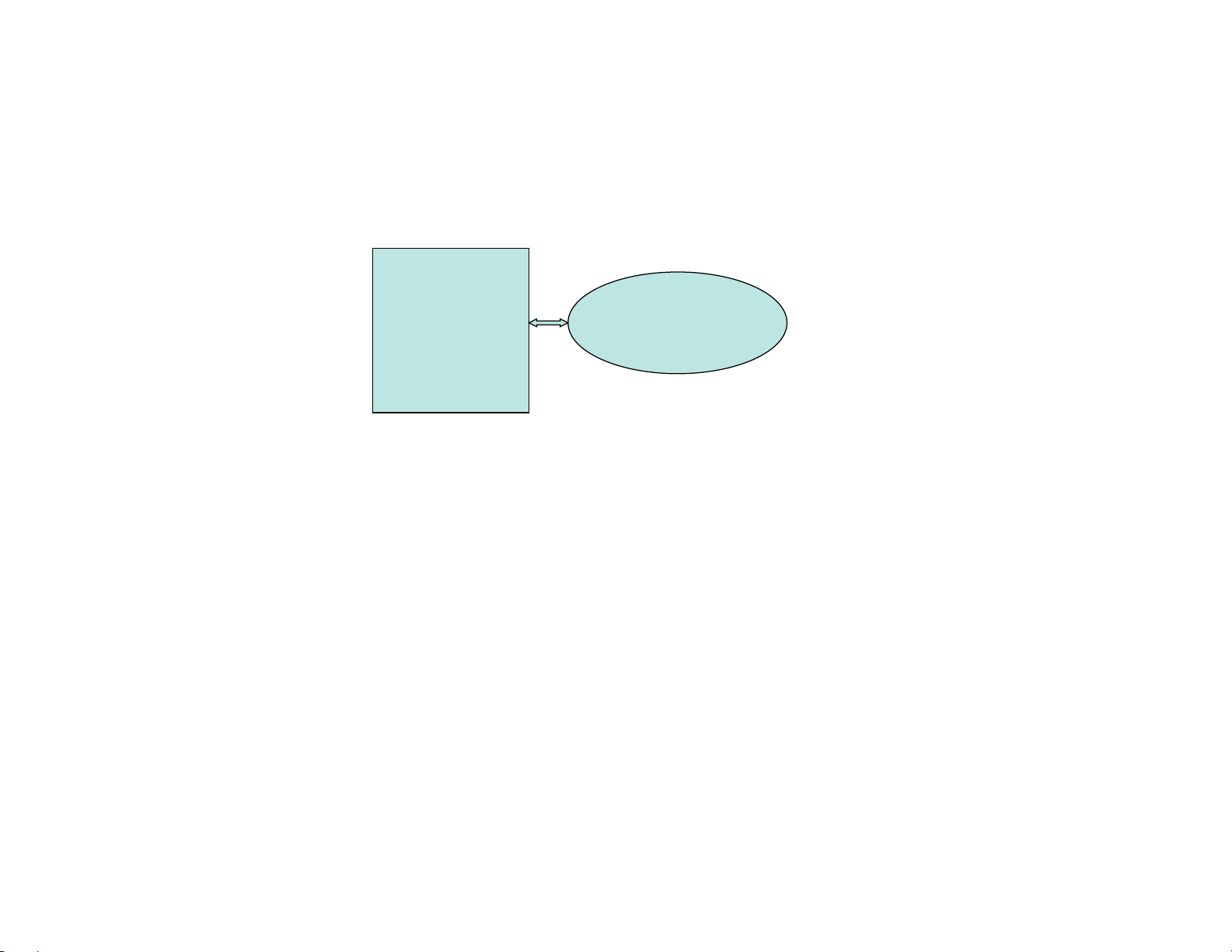
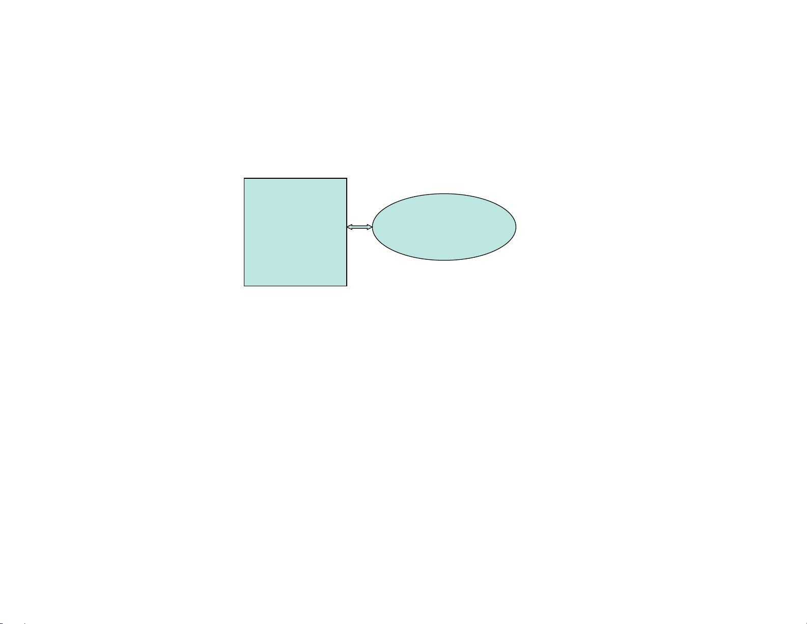
AERCO XPC
AERCO
EQUIPMENT
BUILDING
AUTOMATION
SYSTEM
An extra ground wire must be connected to the earth ground screw in the XPC metal plate.
1.10.1 Quick Setup Guide
22
Page 23
1.10.2 BACNET MS/TP to AERCO XPC
BACNET M S/TP TO AERCO XPC
XPC Port 1a:
• Wir e to Port 1a + to “Net+”, - to “Net-”, and Shi eld connecte d at one end only. If to XPC then to
“Shi eld” connec tor.
8-Position Dipswitch:
• Dipswi tch 1,2 set to BACNET MS/ TP communi cati on baud rate;
• Dipswi tch 3 = Off (B.A. S. on port 1);
• Dipswi tch 4 = O n (EI A485 on port 1) ;
• Dipswitch 5-8 = Off, O ff, Off, Off (for bacnetms/tp(m));
Rotary Address Switches:
• 2 Rotar y Address Swit ches set to BacnetID address for t he XPC)
BE SURE TO CYCLE AERCO XPC POWER AFTER MAKING ANY DIPSWITCH OR JUMPER CHANGES .
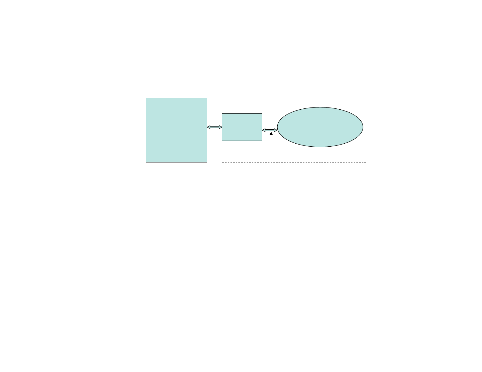
AERCO XPC
BACNET
MS/TP
Port 1a Port 2
RS485
RS485
BAS
bacnet
GF-122 AERCO XPC GATEWAY
23
Page 24
GATEWAY COMMUNICATIONS MANUAL
LON TO AERCO XPC (wit h LON-OC)
XPC “Net” Port on LON-OC:
• Wir e to “Net ” Port on LON-OC Polari ty does not matt er in this case. Connect shield at one end onl y.
8-Position Dipswitch:
• Dipswi tch 1, 2 = On, Off ( 38.4 K baud);
• Dipswi tch 3 = Off (B.A. S. on port 1);
• Dipswi tch 4 = On (por t 1b) ;
• Dipswitch 5-8 = Off, On, On, On (for Lon plug-in).
Rotary Address Switches:
• Not appl icable in thi s case.
Note: Lon XIF fil es are downloada ble from “ www.aerco. com ”.
BE SURE TO CYCLE AERCO XPC POWER AFTER MAKING ANY DIPSWITCH OR JUMPER CHANGES .
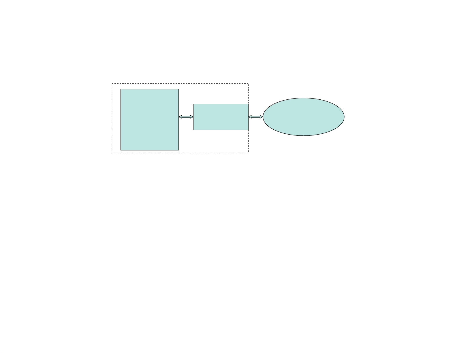
AERCO XPC
LON
Port 1b Port 2
Ftt -10a
BAS
Lon
LON-OC
Net
Ribbon
cable
Ftt-10a
1.10.3 LON to AERCO XPC (with LON-OC)
24
Page 25
1.10.4 LON to AERCO XPC (with SLTA)
LON TO AERCO XPC (with SLTA)
XPC Port 2:
• Wire SLTA to XPC P ort 2 “TX” to “RX”, “RX” to “TX”, “G nd” to “Signal Ground”, and Shield connected at one end only.
• Place 4-position jumper on EIA-232 (t wo top rows);
• Place 2-position jumper on 2W;
• Jumper “DTR” and “DCD” on SLTA port (port 2).
8-Position Dipswitch:
• Dipswitch 1, 2 = On, Off (38.4 K baud);
• Dipswitch 3 = On (B.A.S. on port 2);
• Dips witc h 4 = Off;
• Dips witc h 5-8 = On, Off, On, On (for Lon SLTA).
Rotary Address Switches:
• Not applicable in this case.
Note: Lon XIF files are on enclosed CD or downloadable from “www.aerco. com”.
BE SURE TO CYCLE AERCO XPC POW ER AFTER MAKI NG ANY DI PSW ITCH O R JUMPER CHANG ES.
AERCO XPC
LON
Port 2 Port 1a
Ftt -10a
BAS
Lon
SLTA
Net
Ftt-10a
RS232
RS232
RS232
GF-122 AERCO XPC GATEWAY
25
Page 26
GATEWAY COMMUNICATIONS MANUAL
JOHNSON N2 TO AERCO XPC
XPC Port 1a:
• Wir e to Port 1a + to “Net+”, - to “Net-”, and Shi eld connecte d at one end only. If to XPC then to
“Shi eld” connec tor.
8-Position Dipswitch:
• Dipswi tch 1,2 = Off, Off (9600 baud r ate);
• Dipswi tch 3 = Off (B.A. S. on port 1);
• Dipswi tch 4 = O n (EI A485 on port 1) ;
• Dipswitch 5-8 = On, On, Off, Off ( for N2) ;
Rotary Address Switches:
• 2 Rotar y Address Swit ches set to N2 unit address for the XPC)
BE SURE TO CYCLE AERCO XPC POWER AFTER MAKING ANY DIPSWITCH OR JUMPER CHANGES
AERCO XPC
JOHNSON
N2
RS485
BAS
N2
Port 1a Port 2
RS485
1.10.5 LON to XPC (with LON-OC)
26
Page 27
GF-122 AERCO XPC GATEWAY
AERCO XPC TO BO ILER MANAGEMENT SYSTEM
(BMS)
XPC Part Number:
• “25024-1” for 1 BMS and up t o 4 C-MOREs, or “25024-2” for 1 BM S and up to 12 C-MOREs , or
“25024-4” for 1 BMS and up to 4 MLX Boil ers (wi th BCMs), or 25024-5 for 1 BMS and up to 8 C-MOREs
XPC Port 2 to BMS Port JP12:
• Wir e to XPC Por t 2 “TX ” t o “RXD”, “ RX” to “ TXD” , “ Signal Gr ound” t o “G ND”, and Shiel d connecte d at
one end only t o the BMS at the “SHIELD” i nput. Jumper “ DTR” and “DCD” on port 2.
• Place 4-posi tion j umpe r on EIA-232 ( two top rows) ;
• Place 2-posi tion j umpe r on 2W;
XPC Software Setup:
• Modbus Respons e Ti me = 20(x100 msec) (default);
BMSII RS232 Software Setup:
• RS232 Mode = M odbus Slave; RS232 Baudrate= 9600; Modbus Addr ess = 128; Modbus Pass Thru =
Enabled (if r eading informati on from boi lers, else leave Disabled );
BE SURE TO CYCLE AERCO XPC POWER AFTER MAKING ANY DIPSWITCH OR JUMPER CHANGES
AERCO XPC
BMS
Port 1a Po rt 2
RS232 RS485
RS232
modbus
JP 12 JP 11
1.10.6 AERCO XPC to Boiler Management System (BMS)
27
Page 28
GATEWAY COMMUNICATIONS MANUAL
AERCO XPC TO BO ILER MANAGEMENT SYSTEM II
(BMSII)
XPC Part Number:
• “25024-1” for 1 BMSII and up to 4 C-MORE, or “25024-2” for 1 BMSII and up to 12 C-MOREs , or
“25024-4” for 1 BMSI I and up t o 4 MLX Boil ers ( wit h BCMs) , or 25024-5 for 1 BMSII and up to 8 CMOREs
XPC Port 2 to BMSII Port JP5:
• Wi re to XPC Por t 2 “T X” t o “RXD” , “ RX” to “ TXD” , “ Si gnal Gr ound” t o “G ND”, and Shiel d connecte d at
one end only. If to the BMSII at t he “SHI ELD” input . Jumper “ DTR” and “ DCD” on port 2.
• Place 4-posi tion j umpe r on EIA-232 ( two top rows);
• Place 2-posi tion j umpe r on 2W;
XPC Software Setup:
• Modbus Response Time = 20(x100 msec) (default);
BMSII RS232 Menu Setup:
• RS232 Mode = Modbus Slave; RS232 Baudrate= 9600; Modbus Addr ess = 128; Modbus Pass Thru =
Enabled (if r eading informati on from boi lers, else leave Disabled );
BE SURE TO CYCLE AERCO XPC POWER AFTER MAKING ANY DIPSWITCH OR JUMPER CHANGES
AERCO XPC
BMSII
Port 1a Po rt 2
RS232 RS485RS232
modbus
JP5 JP6
1.10.7 AERCO XPC to Boiler Management System II (BMS II)
28
Page 29
1.10.8 AERCO XPC to C-More
AERCO XPC TO C -MORE
XPC Part Number:
• 25024-1 or 63046-1 for 1 BMS and up to 4 C-MOREs; 25024-2 for 1 BMS and up to 12 C-MOREs; 25024-5 for 1
BMS and up to 8 C-MOREs
XPC Port 2 to C-MORE (I/O Box) RS485:
• Wire to XPC Port 2 “Net+” to “RS485+” , “Net-” to “RS485-”, and Shield connected at one end only - to the C-
MORE (I/O Box) at the “SHLD” input.. Daisy chain to the other units..
• Place 4-position jumper on EIA-485 ( t wo bot t om rows);
• Place 2-position jumper on 2W;
XPC Software Setup:
• Modbus Response Time = 2 (x100 msec); (Must be changed using AppLoader Software and Programmer Cable.)
C-MORE Setup:
• For Monitor Only “Comm Address” = (boiler addr ess s t ar t ing with “1” ) ;
• For M onitor and Remote Setpt Control via Modbus Se t “Comm Address ” as above; Set “Boiler Mode” to
“Remote Setpt” ; Set “Remote Signal” to “Network”.
BE SURE TO CYCLE AERCO XPC POW ER AFTER MAKI NG ANY DI PSW ITCH O R JUMPER CHANG ES
AERCO XPC
C-MORE
Port 1a Po rt 2
RS485 RS485
modbus
GF-122 AERCO XPC GATEWAY
29
Page 30
GATEWAY COMMUNICATIONS MANUAL
AERCO XPC TO BCM (on MLX Boiler )
XPC Part Number:
• 25024-4 or 63046-4 for 1 BMS and up to 4 MLX (with BCM Controls)
XPC Port 2 to BCM Port Y2:
• Wire to XPC Port 2 “Net+” to Y2 pin 1; “Net-” to Y2 pin 2; and Shield connected at one end only - to the XPC at
the “SHIELD” input.. Daisy chain to the other units..
• Place 4-position jumper on EIA-485 ( two bottom rows);
• Place 2-position jumper on 2W;
XPC Software Setup (Must be changed using AppLoader Software and Programmer Cable.):
• Modbus Response Time = 2 (x100 msec); Only if Remote Setpoint control is to be done, set these points from
“False” to “T rue” – “Req Outlet T emp” and “ Net Direct Drive” – for all your boiler addres ses.
BCM Setup:
• Set Addres s Dipswitch on each BCM start ing from 1; Keep termination jumper off on all BCMs;
BE SURE TO CYCLE AERCO XPC POW ER AFTER MAKI NG ANY DI PSW ITCH O R JUMPER CHANG ES
AERCO XPC
BCM
Port 1a Po rt 2
RS485 RS485
modbus
1.10.9 AERCO XPC to BCM (on MLX Boiler)
30
Page 31

1.10.10 AERCO XPC to ECS (with Eurotherm Control)
GF-122 AERCO XPC GATEWAY
31
Page 32

GATEWAY COMMUNICATIONS MANUAL
THIS PAGE INTENTIONALLY LEFT BLANK
32
Page 33

GF-122 AERCO XPC GATEWAY
PART I
AERCO XPC DESCRIPTION
&
SET-UP INSTRUCTIONS FOR INTERFACING
WITH AERCO EQUIPMENT
33
Page 34

GATEWAY COMMUNICATIONS MANUAL
SECTION 2 INTERFACING THE XPC WITH C-MORE CONTROLLED UNITS
2.1 INTRODUCTION
The AERCO XPC Gateway can be connected to any C-More-controlled gas-fired boiler or water heater.
The XPC is configured to work in a “plug-and-play” fashion with AERCO equipment utilizing Modbus
(RS485) communication. The default Modbus communication configuration for all AERCO equipment is
Modbus RTU, 9600 baud, 8 data bits, 1 stop bit, and no parity.
The information in this Section provides basic planning set-up and programming details for implementing
a communication network utilizing the AERCO XPC Gateway with up to 12 C-More controlled boilers or
water heaters. Network control and monitoring is provided by a Master third-party BAS or EMS. Set-up
information for the Master BAS/EMS is provided in the AERCO XPC Gateway Integration Guide, included
as Part II of this manual.
2.2 PHYSICAL NETWORK WIRING
All signal wiring connections between the AERCO XPC Gateway and other AERCO equipment should be
implemented using shielded, twisted-pair wiring from 18 to 24 AWG. Examples of suitable wire types are:
Belden #9841, #8761, #3105A, or equivalent.
The physical locations of the wiring connections necessary to implement a communications network
comprised of the XPC Gateway and AERCO boilers and/or water heaters and a third party BAS or EMS
are provided in the following subsections. Where applicable, connector pinout information is provided for
all AERCO equipment. Refer to the AERCO XPC Gateway Integration Guide (Part II of this manual) for
connection of BAS/EMS equipment used with the XPC Gateway. Also, refer to the BAS/EMS
manufacturer’s equipment manual.
2.3 C-MORE BOILERS OR HEATERS CONTROLLED BY BAS VIA THE GATEWAY
As mentioned in Section 1, C-More Controllers can communicate directly with a BAS utilizing Modbus
RTU protocol via a RS485 network. However, if the BAS does not support Modbus, the XPC Gateway is
required to provide the necessary protocol translation.
All Modbus networks are implemented utilizing a Master-Slave technique where only one device, the
Master, can initiate a communication sequence. AERCO C-More Controllers can only function as Slave
devices on a Modbus network
34
Page 35

GF-122 AERCO XPC GATEWAY
BAS
MASTER
SLAVE
#1
SLAVE
#2
SLAVE#3SLAVE#4SLAVE
#5
XPC
GATEWAY
Modbus RS485 devices should be wired in a “Daisy-Chain” configuration similar to the example shown
Figure 2-1. DO NOT wire the units in a “Star” configuration where all devices are connected to a central
point (node).
Figure 2-1. Typical Daisy-Chain Modbus/RS485 Network
Subsections 2.4 through 2.7 provide the set-up and programming instructions necessary to implement a
communications network utilizing the AERCO XPC and C-More Controller Slaves controlled by a Master
BAS.
2.4 C-MORE CONTROLLER MODBUS COMMUNICATION INTERFACE
The RS485 Modbus communication (COMM) connections for C-More Controller slaves are made in the
Input/Output (I/O) Box shown in Figure 2-2. Identical I/O Boxes are used for Benchmark Boilers and
KC1000 Boilers or Water Heaters. The connections are made at the RS485 COMM terminals labeled +
(plus), and – (minus). Observe the NOTE in Figure 2-2 and never terminate wire shields to the G
(Ground) terminal.
35
Page 36

GATEWAY COMMUNICATIONS MANUAL
Figure 2-2. I/O Box RS485 COMM Terminal Connections
36
Page 37

GF-122 AERCO XPC GATEWAY
2.5 RS485 LOOP TERMINATING RESISTORS AND BIAS
A terminating resistor (120 ohms) on each end of the RS485 loop is designed to match the electrical
impedance characteristic of the twisted-pair loop and prevent echoes or cross-talk from corrupting data
on the line.
Bias may be necessary on the RS485 loop to minimize noise on the circuit. Loop bias is accomplished
by activating pull-up/pull-down resistors on the last C-More Controller in the chain.
When connected directly to the XPC, a terminating resistor should not be needed unless the circuit is
very long (> 2000 feet) or the number of nodes is high (> 20). If termination is activated in the C-More, a
120 Ohm resistor must be placed across the XPC RS-485 connections. Bias is generally not needed
unless excess noise on the bus seems to warrant it. Activating bias, even when not needed, will not harm
the communications.
2.5.1 C-More Boiler Controller Terminating Resistor and Bias
C-More Boiler Controllers can function only as Slave devices on a Modbus Network. Since the Slaves are
connected in a “Daisy-Chain” configuration, the terminating resistor must be enabled only in the last
More Boiler Controller in the chain. In addition, bias must also be implemented only in the last C-More
Boiler Controller. This is accomplished by setting a DIP switches on the Primary Micro-Controller (PMC)
Board contained in the applicable C-More Boiler Controller. The last unit in the chain must be energized
(even if disabled) to enable bias.
C-
To activate the DIP switches, proceed as follows:
Remove power from the last C-More Boiler Controller in the RS485 loop.
Loosen and remove the four (4) screws securing the front panel assembly to the chassis as shown in
Figure 2-3.
Carefully separate the panel from the chassis. Use care to avoid applying undue stress to the ribbon
cable connected between the back of the panel and the chassis-mounted printed circuit boards.
CAUTION
The C-More Boiler Controller Printed Circuit Boards contain electronic
components that are sensitive to electrostatic discharge (ESD). Prior to
performing the following steps, put on an anti-static wrist strap and connect
the clip lead to earth ground. Failure to observe this precaution may result
in permanent damage to on-board ESD-sensitive components.
1. Attach an anti-static wrist strap to your wrist and connect the clip lead to earth ground.
2. From the back of the Panel Assembly (Figure 2-4), locate the RS485 DIP switches on the PMC
Board.
3. Refer to Figure 2-5 and set the “TERM” switch to the ON (Up) position.
4. Set the BIAS2 and BIAS1 switches to the ON (Up) position.
5. After the DIP switches have been set, reposition the Front Panel Assembly on the chassis and secure
it in place with the four screws.
37
Page 38

GATEWAY COMMUNICATIONS MANUAL
FRONT PANEL
SCREWS (4 PL)
THE C-MORE CONTROLLER MODEL SHOWN WITH A
HORIZONTAL PANEL CONTROL LAYOUT IS USED ON KC1000
BOILERS.
BENCHMARK BOILERS UTILIZE C-MORE CONTROLLERS WITH
A VERTICAL PANEL CONTROL LAYOUT.
NOTE:
Figure 2-3. C-More Control Panel - Front View
38
Page 39

GF-122 AERCO XPC GATEWAY
RIBBON
CABLE
RS485
DIP SW.
CONTROL PANEL REAR VIEW – KC1000
C32
Q1
C41
C29
C20
C31
C35
C47
C44
R29
R30
HB
C53
R74
C4
C3
U1
CBS3
R69
C50
R67
R68
Y1
C52
C57
J2
CR1
C1
C5
U17
R76
C51
R71
R73
R72
C2
JP2
R70
U21
C56
C6
C64
R75
J4
U13
U20
C59
C49
C48
C61
CBS4
U14
R78
R79
DS5DS4
RS232
TX
RX
C60
C62
C46
U19
U15
U18
C58
C55
C54
DS3
R77
Y2
U16
C63
B1
R16
U11
R66
U10
R15
C45
R14
C19
C16
R32
R17
C18
R18
C34
U4
R33
C27
R31
C26
U6
R47
C39
R55
U2
R1
C7
U8
R53
C36
R81
R45
R44
C37
R48
S2
R46
C38
R49
J1
BIAS1
TERM
BIAS2
R50
C40
CBS1
RS485
C11
J3
R51
R9
BH1
U3
R10
C12
C13
DS1
RS485
TX
RX
R52
U7
DS2
R54
R5
C10
R7
R8
R6
S1
R11
R65
C9
R34
R12
R13
C14
C15
R36
C28
C25
R35
C23
R37
R38
C30
U5
C43
C65
R2
R3
R58
C8
R62
R4
R80
OFF = VOLT
CURR/VOLT
ON = CURR
Q2
R57
C66
R64
R56
CBS2
R25
U12
R20
U9
R19
C17
R27
R23
R21
R22
C21
R28
R26
C24
R60
R41
R40
R24
R39
C22
R42
R43
C33
R61
R63
C42
R59
CR2
CONTROL PANEL REAR VIEW – BENCHMARK
C32
Q1
C41
C29
C20
C31
C35
C47
C44
R29
R30
HB
C53
R74
C4
C3
U1
CBS3
R69
C50
R67
R68
Y1
C52
C57
J2
CR1
C1
C5
U17
R76
C51
R71
R73
R72
C2
JP2
R70
U21
C56
C6
C64
R75
J4
U13
U20
C59
C49
C48
C61
CBS4
U14
R78
R79
DS5DS4
RS232
TX
RX
C60
C62
C46
U19
U15
U18
C58
C55
C54
DS3
R77
Y2
U16
C63
B1
R16
U11
R66
U10
R15
C45
R14
C19
C16
R32
R17
C18
R18
C34
U4
R33
C27
R31
C26
U6
R47
C39
R55
U2
R1
C7
U8
R53
C36
R81
R45
R44
C37
R48
S2
R46
C38
R49
J1
BIAS1
TERM
BIAS2
R50
C40
CBS1
RS485
C11
J3
R51
R9
BH1
U3
R10
C12
C13
DS1
RS485
TX
RX
R52
U7
DS2
R54
R5
C10
R7
R8
R6
S1
R11
R65
C9
R34
R12
R13
C14
C15
R36
C28
C25
R35
C23
R37
R38
C30
U5
C43
C65
R2
R3
R58
C8
R62
R4
R80
OFF = VOLT
CURR/VOLT
ON = CURR
Q2
R57
C66
R64
R56
CBS2
R25
U12
R20
U9
R19
C17
R27
R23
R21
R22
C21
R28
R26
C24
R60
R41
R40
R24
R39
C22
R42
R43
C33
R61
R63
C42
R59
CR2
RIBBON
CABLE
RS485
DIP SW.
PMC
BOARD
PMC
BOARD
Figure 2-4. C-More Control Panel - Rear Views
39
Page 40

GATEWAY COMMUNICATIONS MANUAL
C32
Q1
C41
C29
C20
C31
C35
C47
C44
R29
R30
HB
C53
R74
C4
C3
U1
CBS3
R69
C50
R67
R68
Y1
C52
C57
J2
CR1
C1
C5
U17
R76
C51
R71
R73
R72
C2
JP2
R70
U21
C56
C6
C64
R75
J4
U13
U20
C59
C49
C48
C61
CBS4
U14
R78
R79
DS5DS4
RS232
TX
RX
C60
C62
C46
U19
U15
U18
C58
C55
C54
DS3
R77
Y2
U16
C63
B1
R16
U11
R66
U10
R15
C45
R14
C19
C16
R32
R17
C18
R18
C34
U4
R33
C27
R31
C26
U6
R47
C39
R55
U2
R1
C7
U8
R53
C36
R81
R45
R44
C37
R48
S2
R46
C38
R49
J1
BIAS1
TERM
BIAS2
R50
C40
CBS1
RS485
C11
J3
R51
R9
BH1
U3
R10
C12
C13
DS1
RS485
TX
RX
R52
U7
DS2
R54
R5
C10
R7
R8
R6
S1
R11
R65
C9
R34
R12
R13
C14
C15
R36
C28
C25
R35
C23
R37
R38
C30
U5
C43
C65
R2
R3
R58
C8
R62
R4
R80
OFF = VOLT
CURR/VOLT
ON = CURR
Q2
R57
C66
R64
R56
CBS2
R25
U12
R20
U9
R19
C17
R27
R23
R21
R22
C21
R28
R26
C24
R60
R41
R40
R24
R39
C22
R42
R43
C33
R61
R63
C42
R59
CR2
SEE DETAIL “A”
S2
BIAS1
TERM
BIAS2
RS485
DETAIL “A”
SET THE BIAS2, TERM & BIAS1
DIP SWITCHES TO THE ON (UP)
POSITION TO ACTIVATE EACH
FUNCTION IF NECESSARY.
PMC BOARD
RIBBON CABLE
CONNECTOR (J1)
Figure 2-5. C-More Control Panel PMC Board
40
Page 41

GF-122 AERCO XPC GATEWAY
EIA-485
EIA-232
2W
4W
2.5.2 BAS Terminating Resistor and Bias
Refer to the BAS manufacturer’s Technical Manual and follow their recommended guidelines for
termination resistors and bias.
NOTE
DO NOT connect C-More boilers to the XPC Gateway as described in
subsection 2.6 if the boilers are being controlled by a BMS Master on the
Modbus network. Refer to Section 3, subsection 3.3 for wiring and set-up
instructions when controlled by the BMS.
2.6 C-MORE CONTROLLER WIRING CONNECTIONS TO AERCO XPC GATEWAY
XPC Port 2 is normally used to connect to AERCO equipment, except when the controlling BAS is
utilizing a LonWorks SLTA module, or communicating via BACnet PTP. In this case, Port 1a of the XPC
must be used to connect AERCO equipment. Therefore, follow the appropriate wiring instructions in
subsection 2.6.1 (Port 2) or 2.6.2 (Port 1a) as applicable.
2.6.1 C-More Wiring Connections to XPC Port 2
When the controlling BAS is utilizing BACnet MS/TP, Johnson N2 or LonWorks protocol without an
SLTA, use XPC Port 2 as follows:
1. Position the EIA-232/EIA-485 and 2W/4W jumpers to EIA-485 and 2W respectively as shown in
Figure 2-6.
Figure 2-6. Port 2 Jumper Settings
2. At the I/O Box for the first C-More Controller, connect the RS-485 COMM terminals as follows:
(a) Connect the RS485 COMM + (plus) terminal to the Net + (plus) terminal on XPC Port 2.
(b) Connect the RS485 COMM – (minus) terminal to the Net – (minus) terminal on XPC Port 2.
(c) DO NOT connect the wire shield to the Ground (G) terminal at the I/O Box. Connect the wire
shield only to the SIGNAL GROUND terminal at XPC Port 2. Refer to Figure 2-7.
41
Page 42

GATEWAY COMMUNICATIONS MANUAL
+
G
-
2W
4W
232
Net +
Net -
N/C
N/C
Tx +
Tx
Tx -
Rx
DTR
Rx -
DCD
SIGNAL
GROUND
Rx +
Port 2
R
E
D
(
+
)
B
L
U
E
(
-
)
S
H
I
E
L
D
RE
D (
+
)
B
L
U
E
(
-)
S
H
I
E
L
D
RED (+)
BLUE (-)
DAISY-CHAIN
TO OTHER UNITS
(
+
TO +, - TO
-)
TIE TOGETHER WITH
SHIELDS OF OTHER
UNITS
C-MORE I/O BOX
RS485 COMM
XPC GATEWAY
+
G
-
R
E
D
(
+
)
B
L
U
E
(
-
)
S
H
I
E
L
D
RE
D
(
+
)
B
L
U
E
(-
)
S
H
I
E
L
D
DAISY-CHAIN
TO OTHER UNITS
(
+
TO
+, -
TO
-)
TIE TOGETHER WITH
SHIELDS OF OTHER
C-MORE UNITS
Net +
Net -
Shield
PORT 1a
C-MORE I/O BOX
RS485 COMM
XPC GATEWAY
RED (+)
BLUE (-)
Figure 2-7. Port 2 Wiring Connections
3. At the XPC Gateway, ensure that DIP switch 3 is set to the OFF (right) position.
2.6.2 C-More Wiring Connections to XPC Port 1a
Connect to XPC Port 1a as follows:
1. At the I/O Box for the first
2. At the XPC Gateway, ensure that DIP switch 3 is set to ON (left) and 4 is set to OFF (right) position.
C-More Controller, connect the RS-485 COMM terminals as follows:
(a) Connect the RS485 + (plus) terminal to the Net + (plus) terminal on XPC Port 1a.
(b) Connect the RS485 – (minus) terminal to the Net – (minus) terminal on XPC Port 1a.
(c) DO NOT connect the wire shield to the Ground (G) terminal at the I/O Box. Connect the wire
shield only to the SIGNAL GROUND terminal at XPC Port 1a. Refer to Figure 2-8.
Figure 2-8. Port 1a Wiring Connections
42
Page 43

GF-122 AERCO XPC GATEWAY
2.7 CONFIGURING THE C-MORE CONTROLLERS
The C-More Boiler Controller can be set up for three types of Modbus (RS485) operating modes. These
modes are as follows:
• Monitoring and Configuration Only
• Modbus Direct Drive Control and Monitoring
• Modbus Remote Setpoint Control and Monitoring
The following subsections provide the procedures necessary to set up the C-More Boiler Controllers for
each of the above modes of operation. These procedures assume that the required wiring connections
for Modbus (RS485) operation have already been accomplished as described in subsection 2.6.
NOTE
The appropriate password must be entered in the Setup Menu of the CMore Controller, prior to changing any of the current settings. Refer to
Section 2 of C-More Controller Operation Manual GF-112 for detailed
information on menu processing procedures.
2.7.1 C-More Controller Monitoring and Configuration Control
Each C-More Controller must be programmed with a distinct network address. The standard XPC
Gateway supports addresses 1 through 12 for C-More controlled boilers or water heaters. Contact
AERCO if additional addresses are required. Proceed as follows to program a valid address at each
More Controller:
1. Scroll through the Setup menu until Comm Address is displayed.
2. With Comm Address displayed, press the CHANGE key.
3. Using the ▲ or ▼ arrow key, enter a valid address between 1 and 12.
4. Press the ENTER key to store the Comm Address in memory.
5. Repeat steps 1 through 4 for each C-More Controller on the Modbus network.
6. Upon power-up, the Gateway will begin to read C-More Controller information after its preliminary
checks.
C-
43
Page 44

GATEWAY COMMUNICATIONS MANUAL
2.7.2 Direct Drive Control and Monitoring
Direct Drive Control of the C-More Boiler Controller is no longer allowed via the AERCO XPC Gateway.
2.7.3 Remote Setpoint Control
Remote Setpoint Control of the C-More Boiler Controller is set up as follows:
1. Enter and store a valid Comm Address using the procedures in subsection 2.7.1.
2. Scroll through the Configuration Menu and change the following menu items to the settings shown:
MENU OPTION
Boiler Mode Remote Setpoint
Remote Signal Network
3. The C-More Controller is now set for Remote Setpoint operation via the RS485 (Modbus) Network.
AERCO recommends that the Setpoint Limiting feature in the Configuration Menu be enabled. Also,
ensure that the Failsafe Mode setting is set to the desired setting (Shutdown or Constant Setpoint) in the
event that the Network signal is lost.
SETTING
44
Page 45

GF-122 AERCO XPC GATEWAY
NOTES:
1. IF BAS CONTAINS A 4-WIRE RS485 PORT,
TIE THE TWO POSITIVE (+) AND NEGATIVE (-)
LEADS TOGETHER AS SHOWN IN DETAIL “A”
2. IF BAS CONTAINS ONLY A RS232 PORT, A
RS232-TO-RS485 CONVERTER WILL BE
REQUIRED.
3. THE LAST C-MORE BOILER ON THE RS485 LOOP
MUST HAVE ITS TERMINATION RESISTOR (TERM)
TURNED ON. ALSO, BIAS (BIAS1, BIAS2) MAY BE
REQUIRED. CHECK WITH THE BAS MANUFACTURER.
+
-
RS485
COMM
(P/O I/O BOX)
C-MORE
NETWORK BOILER 1
-
+
RS485
COMM
P/O I/O BOX
C-MORE
NETWORK BOILER 2
TO OTHER NETWORK
BOILERS
(SEE NOTE 3)
XPC GATEWAY
PORT
1a
NET +
NET -
SHLD
NET +
N/C
N/C
GND
EIA-232
EIA-485
2W
4W
TO BAS
(SEE NOTES)
PORT
2
NET -
RS485
T+
R-
R+
T-
SHIELD
4-WIRE RS485 PORT
DETAIL “A”
C-MOREs CONNECTED TO XPC PORT 2
45
Figure 2-9. C-More Controller Sample Network Diagrams (Sheet 1 of 2)
Page 46

GATEWAY COMMUNICATIONS MANUAL
NOTES:
1. PORT 2 CONNECTIONS AND JUMPER POSITIONS
WILL DEPEND ON THE AVAILABLE PORTS ON THE
BAS BEING USED. SEE DETAIL “A”.
2. THE LAST C-MORE BOILER ON THE RS485 LOOP
MUST HAVE ITS TERMINATION RESISTOR (TERM)
TURNED ON. ALSO, BIAS (BIAS1, BIAS2) MAY BE
REQUIRED. CHECK WITH THE BAS MANUFACTURER.
+
-
RS485
COMM
(P/O I/O BOX)
C-MORE
NETWORK BOILER 1
-
+
RS485
COMM
P/O I/O BOX
C-MORE
NETWORK BOILER 2
TO OTHER NETWORK
BOILERS
(SEE NOTE 2)
XPC GATEWAY
PORT
1a
NET +
NET -
SHLD
EIA-232
EIA-485
2W
4W
TO BAS
(SEE NOTES)
PORT
2
SEE NOTE 1
JUMPERS
2W
4W
232
Net +
Net -
N/C
N/C
Tx +
Tx
Tx -
Rx
DTR
Rx -
DCD
SIGNAL GROUND
Rx +
Port 2
DETAIL “A”
C-MOREs CONNECTED TO XPC PORT 1a
46
Figure 2-9. C-More Controller Sample Network Diagrams (Sheet 2 of 2)
Page 47

GF-122 AERCO XPC GATEWAY
1
9
RS232 PORT
(DB9 - FEMALE)
INTERNAL RS485 & RS232
CONNECTORS LOCATED
BEHIND COVER
(SEE FIGURE 3-2, VIEW A – A)
PANEL
COVER
A
A
SECTION 3 INTERFACING THE XPC TO BOILER MANAGEMENT SYSTEMS
3.1 INTRODUCTION
The XPC Gateway can be connected to either an AERCO BMS, Model 168 or BMS II , Model 5R5-384 to
provide monitoring or control by a third party BAS. The Modbus connection to monitor or control either a
BMS or BMS II is via the unit’s RS232 port.
Although the BMS and BMS II are extremely similar in many respects, separate procedures are provided
in subsections 3.2 (BMS) and 3.3 (BMS II) for the two models to avoid any possible confusion. Refer to
the appropriate procedures related to your installation.
3.2 INTERFACING THE XPC GATEWAY TO BMS, MODEL 158
The BMS (Model 158) contains both an external RS232 port (DB9) and an internal RS232 port. The
external RS232 port is located on the left side of the BMS and the internal RS232 port is located on the
terminal board behind the connection cover of the BMS. These connections are shown in Figures 3-1 and
3-2. The BMS external RS232 and internal RS232/RS485 connector pinouts are shown in Figure 3-3.
Although either RS232 port can be used, AERCO recommends using the internal RS232 port.
Figure 3-1. BMS Left Side View
47
Page 48

GATEWAY COMMUNICATIONS MANUAL
L
N
AUX
FLT
ALARM
SYS
START
SET
BACK
INT2
INT1
4-20
MA
161514
13
12
11
-10
+9
SHIELD 8
REF
TEMP
HDR
TEMP
SEN
SHIELD 3
4
5
6
7
OUT
AIR
SEN
1
2
BLR
1
+1
-2
+3
-4+5-6
+7-8+9
-10
+11
-12
+13
-14
+15
-16
BLR2BLR3BLR4BLR5BLR6BLR7BLR
8
85-265 VAC
JP4
JP3
JP2
+(B)
-(A)
SHLD RXD
TXD
GND
RS485
TO BLRS
RS232
JP11
JP12
VIEW A – A
RS485
CONNECTOR
RS232
CONNECTOR
DB9 (FEMALE)
PIN 5
GND
PIN 3
TxD
PIN 2
RxD
5 1
9
6
RXD
TXD
GND
RS232
JP12
+(B) -(A)
SHLD
RS485
TO BLRS
JP11
NOT
USED
EXTERNAL RS232 PORT
INTERNAL RS485 & RS232 PORTS
RS485 PORT RS232 PORT
Figure 3-2. Partial Front View With Cover Removed
Figure 3-3. BMS RS232 & RS485 Connectors
The following subsections provide the procedures necessary connect the BMS to the XPC Gateway and
configure it for monitoring or remote setpoint control by a BAS.
3.2.1 BMS Set-Up For Monitoring
XPC Gateway Port 2 is normally used to connect to the AERCO BMS, except when the monitoring BAS
is utilizing a LonWorks SLTA, or is communicating via BACnet PTP. In this case, XPC Port 1a must be
used to connect the BMS. Therefore, follow the appropriate wiring instructions in subsection 3.2.1.1 (Port
2) or 3.2.1.2 (Port 1a) as applicable.
48
Page 49

GF-122 AERCO XPC GATEWAY
EIA-485
EIA-232
2W
4W
2W
4W
232
Net +
Net -
N/C
N/C
Tx +
Tx
Tx -
Rx
DTR
Rx -
DCD
SIGNAL
GROUND
Rx +
Port 2
R
E
D
BL
U
E
G
R
E
E
N
(
G
N
D
)
RE
D
B
L
U
E
G
R
E
E
N
(G
N
D
)
RXD
TXD
GND
RS232
JP12
XPC GATEWAY
BMS
JUMPER
3.2.1.1 BMS Wiring Connections to XPC Port 2
When the BAS being used is communicating via BACnet MS/TP, Johnson N2 or LonWorks without an
SLTA, connect to XPC Port 2 as follows:
1. Position the XPC EIA-232/EIA-234 and 2W/4W jumpers to EIA-232 and 2W respectively as shown in
Figure 3-4.
Figure 3-4. Port 2 Jumper Settings
2. Refer to Figures 3-2 and 3-3 to locate the internal RS232 connector inside the wiring area of the
BMS.
3. At the BMS internal RS232 connector (JP12), refer to Figure 3-5 and connect the wire leads as
follows:
(a) Connect the TXD terminal of the BMS RS232 connector to Rx terminal on XPC Port 2.
(b) Connect the RXD terminal of the BMS RS232 connector to Tx terminal on XPC Port 2.
(c) Connect the GND terminal of the BMS RS232 connector to SIGNAL GROUND terminal on XPC
Port 2.
(d) Add a jumper between the DTR and DCD terminals on XPC Port 2. See Figure 1-3 (Detail B).
Figure 3-5. Port 2 Wiring Connections for BMS
4. At the XPC Gateway, ensure that DIP switch 3 is set to the OFF (right) position.
49
Page 50

GATEWAY COMMUNICATIONS MANUAL
RXD
TXD
GND
RS232
JP12
Net +
Net Shield
PORT 1a
XPC GATEWAY
RS232-TO-RS485
CONVERTER
TXD
RXD
GND
GND
B (+)
A
(-)
RED (+)
BLUE (-)
GREEN (GND)
RED
ORANGE
IMPORTANT
CHECK INPUT & OUTPUT
POLARITY ON CONVERTER
BEING USED
BMS
RS232
RS485
+12V
SEE CONVERTER
INSTRUCTIONS
(124958)
3.2.1.2 BMS Wiring Connections to XPC Port 1a
When the BAS being used is communicating via LonWorks with an SLTA, or BACnet PTP, an RS485-toRS232 converter will be required to connect the BMS to Port 1a of the XPC.
1. Refer to Figures 3-2 and 3-3 to locate the internal RS232 connector JP12 inside the wiring area of the
BMS.
2. If the AERCO RS232-to-RS485 Converter (part no. 124942) is used, the RS232 side of the converter
contains a connector that plugs directly into header connector JP12 in the BMS. However, If a third
party converter is used, connect the RS232 receive (RxD) and transmit (TxD) wire leads to the
internal RS232 connector (JP12) as shown in Figure 3-6. DO NOT connect the wire shield on this
side of the converter.
NOTE
If a third-party RS232-to-RS485 Converter is used, consult the
manufacturer’s instruction manual for signal polarity.
3. At the RS485 side of the converter (Figure 3-6), connect the wire leads as follows:
(a) Connect the T D B (+) terminal to the Net + terminal on XPC Port 1a.
(b) Connect the T D A (-) terminal to the Net - terminal on XPC Port 1a.
(c) Connect the GND terminal to the Shield terminal on XPC Port 1a.
Figure 3-6. Port 1a Wiring Connections for BMS
NOTE
A BMS option is available with a built-in RS485-to-232 Converter (part no,
124943). Therefore, AERCO recommends that the internal RS232 be used.
However, the external RS232 port (DB9) can be used if necessary.
4. On the right side of the XPC Gateway Module, check to ensure that DIP switches 3 and 4 are set to
the ON (left) position.
50
Page 51

GF-122 AERCO XPC GATEWAY
3.2.1.3 Configuring the BMS
Once the BMS has been wired to the Gateway as described in subsection 3.2.1.1 or 3.2.1.2, turn on
power to the BMS and perform the following configuration settings:
NOTE
Refer to AERCO Instruction Manual GF-108M for additional information on
BMS keypad functions and displays.
1. Press the FIELD ADJ key on the BMS front panel to enter the Field Adjust mode.
2. Press the AIR TEMP key once. RS2 32 MODE will appear in the top line of the display. If necessary,
press the ▲ or ▼ arrow key until MODBUS SLAVE appears in the second line of the display.
3. Press the AIR TEMP key again. RS232 BAUDRATE will appear in the top line of the display. Press
the ▲ or ▼ arrow key until 9600 appears in second line of the display..
4. Press the AIR TEMP key again. MODBUS ADDRESS will appear in the top line of the display. Press
the ▲ or ▼ arrow key until an address of 128 appears in the second line of the display. Contact
AERCO if another BMS address is required.
5. This completes setup of the BMS.
Refer to subsection 2.3 to connect the required C-More Controllers in a “daisy chain” configuration. Also,
refer to the sample network wiring diagram in Figure 2-9.
NOTE
When the C-More is connected to the AERCO BMS/BMS II, bias and
termination switches must be activated.
Do not proceed to the next step until all required AERCO equipment is connected.
• Turn On the BMS and all of the C-More Controllers.
• Apply 24 VAC power to the XPC Gateway.
Following preliminary power-up checks, the XPC Gateway will begin to read BMS data and allow it to be
controlled by the BAS Master.
3.2.2 C-More Boilers Being Network-Controlled by a BMS
When the BMS is controlling C-More Boilers on the RS485 Modbus network it is the single “Master”
device. No other device, such as the Gateway or a BAS can assume control of the network. However, the
BMS also functions as a communications Gateway which permits a BAS to monitor the BMS as well as
the boilers on the Modbus network. This is accomplished utilizing the RS232 port of the BMS.
The Modbus Pass Thru feature allows AERCO boiler system owners to link their Energy Management
Systems (EMS) and/or Building Automation Systems (BAS) to communicate directly with AERCO C-More
boiler control units as far as reading operational parameters are concerned. In this case, the Boiler
Management System (BMS) simply “passes through” operating parameter information directly from the
C-More boiler control unit to the customer’s EMS/BAS. This is accomplished by enabling the Modbus
Pass Thru feature on the BMS/BMS II units.
51
Page 52

GATEWAY COMMUNICATIONS MANUAL
+
G
-
TERMINATE SHIELD
AT BMS ONLY
+ (B)
- (A)
SHLD
C-MORE I/O BOX
RS485 COMM
BMS RS485
JP11
FIRST UNIT
S
H
I
E
L
D
TIE TOGETHER WITH
SHIELDS OF OTHER
C-MORE UNITS
R
E
D
(
+
)
B
L
U
E
(
-
)
R
E
D
(
+
)
BLUE (-)
Although it is recommended to utilize the AERCO BMS for boiler system control, a customer may opt to
utilize their own boiler system control system. If such is the case, the BMS/BMS II may be removed
entirely allowing the customer’s BAS/EMS system to interact directly (possibly using a protocol
translating XPC Communications Gateway device, if needed) with the C-More boiler controller. If the
BMS/BMS II is kept in the loop and Modbus Pass Thru is enabled, those control functions normally set by
the BMS/BMS II will continue to do so. All other control functions will now be facilitated by BAS/EMS
commands passed thru the BMS/BMS II directly to the C-More boiler controller.
If the BAS being utilized supports Modbus RTU protocol, it can be connected to the BMS either directly or
via a RS485-to-RS232 converter. However, if the BAS does not support Modbus protocol and utilizes
BACnet, N2 or LonWorks, the AERCO XPC Gateway must be used as described below.
1. Make the connections between the BMS and XPC Gateway as instructed in subsections 3.2.1.1 or
3.2.1.2.
2. Set up the C-More Boiler Controllers as described in Section 2, subsections 2.3 through 2.5.1.
3. Connect the C-More Boiler Controllers in a “Daisy-Chain” configuration.
4. Refer to Figure 3-7 and connect the RS485 COMM terminals of the first
internal RS485 connector JP11 as follows:
(a)
(a) Connect the RS485 COMM + terminal to the +(B) terminal of JP11 in BMS.
(b) Connect the RS485 COMM - terminal to the -(A) terminal of JP11 in BMS.
(c) Terminate the shield at the BMS end only.
Figure 3-7. BMS Connections to C-More Controller
C-More Boiler to the BMS
5. With the BMS in the Field Adjust Mode, continue pressing the AIR TEMP key until MODBUS PASS
6. With PASS THRU set to ENABLED, both the BMS and the boilers can now be monitored.
NOTE
Refer to AERCO Instruction Manual GF-108M for additional information on
BMS keypad functions and displays.
THRU is displayed. Press the ▲ or ▼ arrow key until the second line of the display shows
ENABLED.
52
Page 53

GF-122 AERCO XPC GATEWAY
NOTE
The Gateway Response Time for Modbus must be adjusted to 2 seconds in
order for the communication to work efficiently. This is due to the extra lag
in communications to the boiler when going through the BMS. Since the
BMS control operations take priority, it may delay the processing of a
Gateway command by a second or two depending on what it is doing at the
moment.
3.2.3 BMS Setup For Remote Setpoint Control From the XPC Gateway
For remote setpoint control of a BMS, set up the wiring connections as described in subsection 3.2. Upon
completion of all wiring connections, configure the BMS as follows:
1. Press the FIELD ADJ key on the BMS front panel to enter the Field Adjust Mode. The yellow LED on
the key should be lit.
2. Press the AIR TEMP key until RS2 32 MODE is shown on the top line of the display. If necessary,
press the ▲ or ▼ arrow key until MODBUS SLAVE appears in the second line of the display.
3. Press the AIR TEMP key again until RS232 BAUDRATE is shown on the top line of the display.
Press the ▲ or ▼ arrow key to select a baud rate of 9600.
4. Press the AIR TEMP key again until MODBUS ADDRESS is shown on the top line of the display.
Press the ▲ or ▼ arrow key to set the BMS address to 128.
5. Press the FIELD ADJ key to exit the Field Adjust Mode. The yellow LED on the key should go off.
6. To set the BMS for Remote Operation, press the CONFIG SYS key to enter the System Configuration
mode. The red LED on the key will light.
7. Press the FIELD ADJ key until HDR SET MODE is shown in the top line of the display. Press the ▲
or ▼ arrow key to select REMOTE SET TEMP.
8. Press the CONFIG SYS key to exit the System Configuration Mode. The red LED on the key will go
off.
The BMS is now set up for Remote Setpoint control by a BAS. In the event of control signal interruption,
AERCO recommends that the TEMP FAIL MODE setting be set to SWITCH INPUTS if you want the
BMS to continue running the boilers in the CONSTANT SET TEMP mode. In this case, ensure that the
REF TEMP is set to the desired setpoint temperature.
NOTE
Sample network diagrams showing the BMS connected to Port 2 and Port
1a of the AERCO XPC Gateway are provided in Figure 3-8. These samples
are intended for reference purposes only and do not depict all possible
network scenarios.
53
Page 54

GATEWAY COMMUNICATIONS MANUAL
NOTE:
PORT 1a CONNECTIONS WILL DEPEND ON THE
AVAILABLE PORTS ON THE BAS BEING USED.
IF THE BAS CONTAINS A 4-WIRE RS485 PORT, SEE
DETAIL “A”.
IF THE BAS CONTAINS ONLY A RS232 PORT, A
RS485-TO-RS232 CONVERTER WILL BE REQUIRED.
RXD
TXD
GND
+(B)
-(A)
SHLD
TO C-MORE
BOILERS
CONTROLLED
VIA RS485
NETWORK
BMS
JP11
JP12
RS232
XPC GATEWAY
PORT
1a
NET +
NET -
SHLD
TX
DTR
DCD
GND
EIA-232
EIA-485
2W
4W
TO BAS
(SEE NOTE)
PORT
2
RX
RS485
T+
R-
R+
T-
SHIELD
4-WIRE RS485 PORT
DETAIL “A”
NOTE:
PORT 2 CONNECTIONS AND JUMPER POSITIONS
WILL DEPEND ON THE AVAILABLE PORTS ON THE
BAS BEING USED. SEE DETAIL “A”.
XPC GATEWAY
PORT
1a
NET +
NET -
SHLD
EIA-232
EIA-485
2W
4W
TO BAS
(SEE NOTE)
PORT
2
SEE NOTE
JUMPERS
RS485-TO- RS232
CONVERTER
RXD
TXD
GND
+(B)
-(A)
SHLD
TO C-MORE
BOILERS
CONTROLLED
VIA RS485
NETWORK
BMS
JP11
JP12
RS232
RS485
2W
4W 232
Net +
Net -
N/C
N/C
Tx + Tx
Tx - Rx
DTR
Rx - DCD
SIGNAL GROUND
Rx +
Port 2
DETAIL “A”
B+
A-
GND
RXD
TXD
GND
+12V
SEE CONVERTER
INSTRUCTIONS
(124958)
BMS CONNECTED TO XPC PORT 2
Figure 3-8. BMS Sample Network Diagrams (Sheet 1 of 2)
BMS CONNECTED TO XPC PORT 1a
Figure 3-8. BMS Sample Network Diagrams (Sheet 2 of 2)
54
Page 55

GF-122 AERCO XPC GATEWAY
SENSORS
& 4-20 mA
INTERLOCKS
& SETBACK
RS485
& RS232
AC POWER
RELAYS
3.3 INTERFACING THE XPC GATEWAY TO BMS II, MODEL 5R5-384
The BMS II (Model 5R5-384) contains an internal RS232 port which provides Modbus connections to the
XPC Gateway. In addition, the BMS II contains an internal RS485 port which provides monitoring and
control of the Boilers connected to the BMS II. These internal RS232 and RS485 ports are located on the
terminal board behind the wiring compartment cover of the BMS II. These locations and connector
pinouts for these ports are shown in Figures 3-9 and 3-10.
Figure 3-9. BMS II With Wiring Compartment Cover Removed
55
Page 56

GATEWAY COMMUNICATIONS MANUAL
ISO
12V
RXD
TXD
232
ISOGND
485
ISOGND
485 A
485 B
RS232
RS485
JP5
JP6
EIA-485
EIA-232
2W
4W
Figure 3-10. BMS II RS232 & RS485 Pinout Assignments
3.3.1 BMS II Set-Up For Monitoring
XPC Gateway Port 2 is normally used to connect to the AERCO BMS, except when the monitoring BAS
is utilizing a LonWorks SLTA, or is communicating via BACnet PTP. In this case, XPC Port 1a must be
used to connect the BMS. Therefore, follow the appropriate wiring instructions in subsection 3.3.1.1 (Port
2) or 3.3.1.2 (Port 1a) as applicable.
3.3.1.1 BMS Wiring Connections to XPC Port 2
When the BAS being used is communicating via BACnet MS/TP, Johnson N2 or LonWorks without an
SLTA, connect to XPC Port 2 as follows:
1. Position the XPC EIA-232/EIA-485 and 2W/4W jumpers to EIA-232 and 2W respectively as shown in
Figure 3-11.
Figure 3-11. Port 2 Jumper Settings
2. Refer to Figures 3-9 and 3-10 to locate the internal RS232 connector inside the wiring area of the
BMS II.
3. At the BMS II internal RS232 connector (JP5), refer to Figure 3-12 and connect the wire leads as
follows:
(a) Connect the TXD terminal of the BMS RS232 connector to Rx terminal on XPC Port 2.
(b) Connect the RXD terminal of the BMS RS232 connector to Tx terminal on XPC Port 2.
(c) Connect the GND terminal of the BMS RS232 connector to SIGNAL GROUND terminal on XPC
Port 2.
(d) Add a jumper between the DTR and DCD terminals on the XPC Port 2. See Figure 1-3 (Detail B).
56
Page 57

GF-122 AERCO XPC GATEWAY
2W 4W 232
Net +
Net -
N/C
N/C
Tx +
Tx
Tx - Rx
DTR
Rx -
DCD
SIGNAL
GROUND
Rx +
Port 2
R
E
D
BL
UE
G
R
E
E
N
(
G
N
D
)
RE
D
B
L
U
E
G
R
EE
N
(
G
N
D
)
XPC GATEWAY
BMS II
JUMPER
232
ISO GND
TXD
RXD
ISO 12V
JP5
Figure 3-12. Port 2 Wiring Connections for BMS
4. At the XPC Gateway, ensure that DIP switch 3 is set to the OFF (right) position.
3.3.1.2 BMS II Wiring Connections to XPC Port 1a
When the BAS being used is communicating via LonWorks with an SLTA, or BACnet PTP, an RS485-toRS232 converter will be required to connect the BMS to Port 1a of the XPC.
1. Refer to Figures 3-9 and 3-10 to locate the internal RS232 connector JP5 inside the wiring area of the
BMS.
2. If the AERCO RS232-to-RS485 Converter (part no. 124942) is used, the RS232 side of the converter
contains a connector that plugs directly into header connector JP5 in the BMS II. However, If a third
party converter is used, connect the RS232 receive (RxD) and transmit (TxD) wire leads to the
internal RS232 connector (JP5) as shown in Figure 3-13. DO NOT connect the wire shield on this
side of the converter.
NOTE
If a third-party RS232-to-RS485 Converter is used, consult the
manufacturer’s instruction manual for signal polarity.
3. At the RS485 side of the converter (Figure 3-13), connect the wire leads as follows:
(a) Connect the TD B (+) terminal to the Net + terminal on XPC Port 1a.
(b) Connect the TD A (-) terminal to the Net - terminal on XPC Port 1a.
(c) Connect the GND terminal to the Shield terminal on XPC Port 1a.
57
Page 58

GATEWAY COMMUNICATIONS MANUAL
Net +
Net -
Shield
PORT 1a
XPC GATEWAY
RS232-TO-RS485
CONVERTER
TXD
RXD
GND
GND
B (+)
A
(-)
RED (+)
BLUE (-)
GREEN (GND)
RED
ORANGE
IMPORTANT
CHECK INPUT & OUTPUT
POLARITY ON CONVERTER
BEING USED
BMS
RS232 RS485
232
ISO GND
TXD
RXD
ISO 12V
JP5
+12V
GND
Figure 3-13. Port 1a Wiring Connections for BMS
NOTE
A BMS II option is available with a built-in RS485-to-232 Converter (part no,
124943).
4. On the right side of the XPC Gateway Module, check to ensure that DIP switches 3 and 4 are set to
the ON (left) position.
3.3.1.3 Configuring the BMS II
Once the BMS II has been wired to the Gateway as described in subsection 3.3.1.1 or 3.3.1.2, turn on
power to the BMS II and perform the following configuration settings:
NOTE
Refer to AERCO Instruction Manual GF-124 for additional information on
BMS II keypad functions and displays.
1. Press the MENU key and go to the SETUP MENU.
2. Press the ▲ arrow key. ENT ER PASSWORD will be displayed requesting the valid password to be
entered.
3. Using the ▲ and ▼ arrow keys, enter the valid level 1 password (159) and then press the ENTER
key. LEVEL 1 PASSWORD will be displayed.
4. Press the MENU key again. RS232 MENU is displayed.
5. Press the ▲ arrow key. RS232 MODE appears in the first line of the display.
6. If MODBU S SLAVE is not
toggle the display to MODBUS SLAVE. Press the ENTER key to store the setting.
displayed in the second line of the display, press the CHANGE key and
7. While still in the RS232 MENU, press the ▲ arrow key. RS232 BAUDRATE is displayed in the first
line of the display.
8. If 9600 i s not
using the ▲ or ▼ arrow key. Press the ENTER key to store the 9600 Baud Rate.
displayed in the second line of the display, press the CHANGE key and select 9600
58
Page 59

GF-122 AERCO XPC GATEWAY
9. Press the ▲ arrow key again. MODBUS ADDRESS appears in the first line of the display.
10. Press the CHANGE key and select the desired Modbus address for the BMS II using the ▲ and
▼arrow keys. Press the ENTER key to store the selected address.
11. This completes the required configuration setup for the BMS II.
Refer to subsection 2.3 to connect the required C-More Controllers in a “daisy chain” configuration. Also,
refer to the sample network wiring diagram in Figure 2-9. Do not proceed to the next step until all
required AERCO equipment is connected.
• Turn On the BMS II and all of the C-More Controllers.
• Apply 24 VAC power to the XPC Gateway.
Following preliminary power-up checks, the XPC Gateway will begin to read BMS II data and allow it to
be controlled by the BAS Master.
3.3.2 C-More Boilers Being Network-Controlled by a BMS II
When the BMS II is controlling C-More Boilers on the RS485 Modbus network it is the single “Master”
device. No other device, such as the XPC Gateway or a BAS can assume control of the network.
However, the BMS II also functions as a communications Gateway which permits a BAS to monitor the
BMS II as well as the boilers on the Modbus network. This is accomplished utilizing the RS232 port of the
BMS II.
If the BAS being utilized supports Modbus RTU protocol, it can be connected to the BMS II either directly
or via a RS485-to-RS232 converter. However, if the BAS does not support Modbus protocol and utilizes
BACnet, N2 or LonWorks, the AERCO XPC Gateway must be used as described below.
1. Make the connections between the BMS II and XPC Gateway as instructed in subsections 3.3.1.1 or
3.3.1.2.
2. Set up the C-More Boiler Controllers as described in Section 2, subsections 2.3 through 2.5.1.
3. Connect the C-More Boiler Controllers in a “Daisy-Chain” configuration.
4. Refer to Figure 3-14 and connect the RS485 COMM terminals of the first
RS485 connector JP6 as follows:
(a) Connect the RS485 COMM + terminal to the 485 B terminal of JP6 in the BMS II.
(b) Connect the RS485 COMM - termin al to the 485 A terminal of JP6 in the BMS II.
(c) On the BMS II, connect the shield to SHLD terminal no. 3 NOT
the BMS II RS485 connector (JP6).
NOTE
Be sure to activate the termination and bias resistors by setting the DIP
switches on the last C-More when connected to the BMS II.
C-More Boiler to the BMS II
to the 485 ISOGND terminal of
59
Page 60

GATEWAY COMMUNICATIONS MANUAL
+
G
-
TERMINATE SHIELD
AT BMS II ONLY
C-MORE I/O BOX
RS485 COMM
FIRST UNIT
S
H
I
E
L
D
TIE TOGETHER WITH
SHIELDS OF OTHER
C-MORE UNITS
R
E
D
(
+
)
B
L
U
E
(
-
)
R
E
D
(
+
)
B
L
U
E
(
-
)
SHLD
(JP7, TERM. #3)
485 A
485 B
ISO GND
BMS II RS485 (JP6)
Figure 3-14. BMS II Connecti ons to C-More Controller
NOTE
Refer to AERCO Instruction Manual GF-124 for additional information on
BMS II keypad functions, displays and password entries.
5. With the BMS II in the RS232 MENU, scroll to the MODBUS PASS THRU menu option.
6. If ENABLED is not
displayed in the second line of the display, press the CHANGE key and toggl e the
display to ENABLED using the ▲ or ▼ arrow key. Press the ENTER key to store the setting.
7. With MODBUS PASS THRU set to ENABLED, both the BMS II and the boilers can now be
monitored.
NOTE
The Gateway Response Time for Modbus must be adjusted to 2 seconds in
order for the communication to work efficiently. This is due to the extra lag
in communications to the boiler when going through the BMS II. Since the
BMS II control operations take priority, it may delay the processing of a
Gateway command by a second or two depending on what it is doing at the
moment.
3.3.3 Modulex Boilers Being Network-Controlled by a BMS II
When the BMS II is controlling C-More Boilers on the RS485 Modbus network it is the single “Master”
device. No other device, such as the XPC Gateway or a BAS can assume control of the network.
However, the BMS II also functions as a communications Gateway which permits a BAS to monitor the
BMS II as well as the boilers on the Modbus network. This is accomplished utilizing the RS232 port of the
BMS II.
If the BAS being utilized supports Modbus RTU protocol, it can be connected to the BMS II either directly
or via a RS485-to-RS232 converter. However, if the BAS does not support Modbus protocol and utilizes
BACnet, N2 or LonWorks, the AERCO XPC Gateway must be used as described below.
60
Page 61

GF-122 AERCO XPC GATEWAY
1. Make the connections between the BMS II and XPC Gateway as instructed in subsections 3.3.1.1 or
3.3.1.2.
2. Refer to Figure 3-15 and make connections between Boiler Control Module (BCM) of the Modulex
Boiler as follows:
(a) Connect terminal 1 of BCM connector Y2 to the 485 B terminal on the BMS II RS485 connector
JP6.
(b) Connect terminal 2 of BCM connector Y2 to the 485 A terminal on the BMS II RS485 connector
JP6.
(c) Terminate the shield at the BMS SHLD terminal no. 3 (JP7).
3. Connect the BCM Controllers in a “Daisy-Chain” configuration. Tie all shields together between the
BCMs on the network.
4. On the last BCM module in the daisy chain connect the termination jumper.
5. On the BMS II, activate the 2 bias DIP switches by pushing them both down (towards the PCB).
3.3.4 BMS II Setup For Remote Setpoint Control From The XPC Gateway
For remote setpoint control of a BMS II, set up the wiring connections as described in subsection 3.3.1.
Upon completion of all wiring connections, configure the BMS II as follows:
NOTE
Refer to AERCO Instruction Manual GF-124 for additional information on
BMS II keypad functions and displays.
1. Press the MENU key and go to the SETUP MENU.
2. Press the ▲ arrow key. ENTER PASSWORD will be displayed requesting the valid password to be
entered.
3. Using the ▲ and ▼ arrow keys, enter the valid level 1 password (159) and then press the ENTER
key. LEVEL 1 PASSWORD will be displayed.
4. Press the MENU key and go to the FIELD ADJUST MENU.
5. Using the ▲ or ▼ arrow key, go to the HEADER SET MODE option.
6. If REMOTE SETPOINT is not
select REMOTE SETPOINT using the ▲ or ▼ arrow key. Press the ENTER key to store the
selection.
7. Next, press the ▲ arrow key and go to the REMOTE SIGNAL option.
8. If MODBUS is not
display to MODBUS. Press the ENTER key to store the selection.
The BMS II is now set up for Remote Setpoint control from a XPC Gateway. In the event of control signal
interruption from the XPX, AERCO recommends that the FAIL SAFE MODE option in the
CONFIGURATION MENU be set to CONSTANT SETPOINT with the INTERNAL SETPT (FIELD
ADJUST MENU) set to the desired temperature.
displayed in the second line of the display, press the CHANGE key and toggle the
displayed in the second line of the display, press the CHANGE key and
61
Page 62

GATEWAY COMMUNICATIONS MANUAL
NOTE
Sample network diagrams showing the BMS II connected to Port 2 and Port
1a of the AERCO XPC Gateway are provided in Figure 3-15. These
samples are intended for reference purposes only and do not depict all
possible network scenarios.
62
Page 63

GF-122 AERCO XPC GATEWAY
NOTE:
PORT 1a CONNECTIONS WILL DEPEND ON THE
AVAILABLE PORTS ON THE BAS BEING USED.
IF THE BAS CONTAINS A 4-WIRE RS485 PORT, SEE
DETAIL “A”.
IF THE BAS CONTAINS ONLY A RS232 PORT, A
RS485-TO-RS232 CONVERTER WILL BE REQUIRED.
RXD
TXD
GND
+(B)
-(A)
SHLD
TO C-MORE
OR MODULEX
BOILERS
CONTROLLED
VIA RS485
NETWORK
BMS II
JP6
JP5
RS232
XPC GATEWAY
PORT
1a
NET +
NET -
SHLD
TX
DTR
DCD
GND
EIA-232
EIA-485
2W
4W
TO BAS
(SEE NOTE)
PORT
2
RX
RS485
T+
R-
R+
T-
SHIELD
4-WIRE RS485 PORT
DETAIL “A”
NOTE:
PORT 2 CONNECTIONS AND JUMPER POSITIONS
WILL DEPEND ON THE AVAILABLE PORTS ON THE
BAS BEING USED. SEE DETAIL “A”.
XPC GATEWAY
PORT
1a
NET +
NET SHLD
EIA-232
EIA-485
2W
4W
TO BAS
(SEE NOTE)
PORT
2
SEE NOTE
JUMPERS
RS485-TO- RS232
CONVERTER
RS232
RS485
2W
4W 232
Net +
Net -
N/C
N/C
Tx +
Tx
Tx -
Rx
DTR
Rx - DCD
SIGNAL GROUND
Rx +
Port 2
DETAIL “A”
B+
A-
GND
RXD
TXD
GND
RXD
TXD
GND
+(B)
-(A)
SHLD
TO C-MORE
OR MODULEX
BOILERS
CONTROLLED
VIA RS485
NETWORK
BMS II
JP6
JP5
JP7
+12V
ISO
12V
ISO
GND
BMS II CONNECTED TO XPC PORT 2
BMS II CONNECTED TO XPC PORT 1a
63
Figure 3-15. BMS II Sample Network Diagrams
Page 64

GATEWAY COMMUNICATIONS MANUAL
SECTION 4 AERCO XPC GATEWAY TO BCM
CONTROLLED MODULEX BOILERS
4.1 CONNECTION AND SET-UP OF BOILER COMMUNICATIONS MODULES (BCMS)
The BCM is used to provide Modbus (RS485) connectivity for AERCO Modulex Series Boilers. When
equipped with BCMs, the Modulex Boilers can be monitored and/or controlled by a BAS via the AERCO
XPC Gateway. Modbus (RS485) connections are made at BCM connector Y2. Proceed as follows to
access the BCM wiring connections:
1. Disconnect all power from the Modulex Boiler.
2. Remove the top and front covers from the Modulex Boiler to provide access to the BCM.
3. Refer to Figure 4-1 and locate the BCM switches on the front of the unit.
4. Remove the four screws securing the BCM mounting bracket and separate the bracket from the back
of the panel to provide access to the BCM connectors.
5. Locate the Modbus wiring connections on BCM connector Y2 (Figure 4-2).
6. Proceed to subsection 4.2 and wire the BCM to the appropriate XPC port connector for the
application being used.
Figure 4-1. Modulex Boiler With BCM
64
Page 65

GF-122 AERCO XPC GATEWAY
7 6 5 4 3 2 1
Y2
Y2
Y3
Y4
Y1
SW1
A1
I
0
MODBUS A (-)
MODBUS B (+)
BCM FRONT VIEW
EIA-485
EIA-232
2W
4W
4.2 BCM WIRING CONNECTIONS TO AERCO XPC GATEWAY
XPC Port 2 is normally used to connect to AERCO equipment, except when the controlling BAS is
utilizing a LonWorks SLTA module, or communicating via BACnet PTP. In this case, Port 1a of the XPC
must be used to connect AERCO equipment. Therefore, follow the appropriate wiring instructions in
subsection 4.2.1 (Port 2) or 4.2.2 (Port 1a) as applicable.
4.2.1 BCM Wiring Connections to XPC Port 2
When the controlling BAS is utilizing BACnet MS/TP, Johnson N2 or LonWorks protocol without an
SLTA, use XPC Port 2 as follows:
1. On the XPC Gateway, position the EIA-232/EIA-485 and 2W/4W jumpers to EIA-485 and 2W
respectively as shown in Figure 4-3.
Figure 4-2. BCM Modbus (RS485) Connections
65
Page 66

GATEWAY COMMUNICATIONS MANUAL
2
1
TERMINATE SHIELD
AT XPC ONLY
BCM
CONNECTOR Y2
FIRST UNIT
SH
I
E
L
D
TIE TOGETHER WITH
SHIELDS OF OTHER
C-MORE UNITS
R
E
D
(
+)
B
L
U
E
(
-
)
R
E
D
(
+)
B
L
UE
(
-
)
5
4
6
3
7
2W
4W 232
Net +
Net N/C
N/C
Tx +
Tx
Tx -
Rx
DTR
Rx - DCD
SIGNAL
GROUND
Rx +
Port 2
XPC GATEWAY
DAISY-CHAIN
TO OTHER UNITS
(+ TO +, - TO -)
RED (+)
BLUE (-)
Figure 4-3. Port 2 Jumper Settings
2. Connect BCM terminals Y2-1 and Y2-2 to XPC Port 2 (Figure 4-4) as follows:
(a) Connect the Y2-1 (Modbus B +) terminal to the “NET +” terminal of Port 2 on the XPC
(b) Connect the Y2-2 (Modbus A -) terminal to the “NET -” terminal of Port 2 on the XPC.
3. On the XPC Gateway, check to ensure that DIP switch 3 is set to the OFF position.
4.2.2 BCM Wiring Connections to XPC Port 1a
When the controlling BAS is connected to Port 2 and is using a LonWorks SLTA or communicating via
BACnet PTP, connect the BCM to XPC Port 1a as follows:
1. Connect BCM terminals Y2-1 and Y2-2 to XPC Port 1a (Figure 4-5) as follows:
Figure 4-4. XPC Port 2 Connections to BCM
NOTE
The positions of the EIA-232/EIA-485 and 2W/4W jumpers will depend on
the available ports on the controlling BAS being used.
(a) Connect the Y2-1 (Modbus B +) terminal to the “NET +” terminal of Port 1a on the XPC
(b) Connect the Y2-2 (Modbus A -) terminal to the “NET -” terminal of Port 1a on the XPC.
66
Page 67

GF-122 AERCO XPC GATEWAY
2
1
TERMINATE SHIELD
AT XPC ONLY
BCM
CONNECTOR Y2
FIRST UNIT
S
H
I
EL
D
TIE TOGETHER WITH
SHIELDS OF OTHER
BCM UNITS
R
E
D
(
+)
B
L
U
E
(
-
)
R
E
D
(
+
)
B
L
U
E
(
-
)
5
4
6
3
7
Net +
Net -
Shield
PORT 1a
XPC GATEWAY
DAISY-CHAIN
TO OTHER UNITS
(+ TO +, - TO -)
RED (+)
BLUE (-)
Figure 4-5. XPC Port 1a Connections to BCM
2. On the XPC Gateway, check to ensure that DIP switches 3 and 4 are set to ON.
4.3 CONFIGURING THE BCM CONTROLLER
Refer to AERCO manual GF-115-C, Section 7 and program a communication address between 1 and 4
for the standard XPC Gateway. Ensure that each BCM Controller on the network has its own distinct
address. Contact AERCO if more than 4 BCM uni ts will be placed on the network or a different address
range is required.
1. Set the communications baud rate to 9600.
2. This completes the required connections and settings and for the BCM.
3. Reattach the BCM mounting bracket to the front of the Modulex Boiler and replace all removed
Upon power-up, the Gateway should begin to read the BCM information after its preliminary checks.
panels.
67
Page 68

GATEWAY COMMUNICATIONS MANUAL
SECTION 5 XPC GATEWAY TO
ECS CONTROLLED HOT WATER HEATERS
5.1 CONNECTION AND SET-UP OF ELECTRONIC CONTROL SYSTEM (ECS)
The AERCO Electronic Control System (ECS) used to control indirect fired water heaters can be
connected to an RS485 Modbus network, when equipped with an optional Communications Board
(AERCO part no. 64009). RS485 Modbus connections to the ECS are made on the rear of the
Temperature Controller (Eurotherm 2408) contained in the Control Box. Proceed as follows to access the
Temperature Controller wiring connections:
1. Disconnect power from the ECS Control Box.
2. Loosen the captive screw on the right-front portion of the Control Box (Figure 5-1) to open the hinged
panel door.
PANEL
DOOR
CAPTIVE
SCREW
2408
RUNAUTO
HOLD
MAN
TEMP CONTROLLER
B-PLUS
OVER TEMP SWITCH
TM
WATER HEATER
PT.NO.
PT.NO.
Figure 5-1. ECS Control Panel Front View
3. Next, open the door and loosen the captive screw at the top of the recessed panel (Figure 5-2).
Swing down the recessed panel to access the rear wiring connections on the Temperature Controller
(Figure 5-3).
68
Page 69

GF-122 AERCO XPC GATEWAY
PANEL CAPTIVE
SCREW
B-PLUS
TM
PT.NO.
SET
F
AUTO
RUN
MAN HOLD
OP 1
OP 2
SP2
REM
2408
OVER TEMP SWITCH
TEMP CONTROLLER
PT.NO.
WATER HEATER
OVERTEMP SWITCH
2408 TEMPERATURE
CONTROLLER
PANEL REAR
Figure 5-2. Recessed Panel Behind Control Box Door
Figure 5-3. Control Box Swing-Down Panel Rear View (Steam-to-Water Unit)
69
Page 70

GATEWAY COMMUNICATIONS MANUAL
1A
HA
1B
HB
1C
HC
2A
2B
1D
HE
HF
HD
3B
3D
3C
2D
3A
2C
JD
JF
JE
JB
JC
JA
LA
LB
LC
AA
AB
AC
VI
V+
V-
In1
In2
C
2408 CONTROLLER
L
N
RS485
MODBUS
CONNECTIONS
EIA-485
EIA-232
2W
4W
4. Refer to the Temperature Controller RS485 terminal connections shown in Figure 5-4.
Figure 5-4. Temperature Controller (Eurotherm 2408) Terminal Connections
5. Proceed to subsection 5.2 and wire the ECS to the appropriate XPC port connector for the application
being used.
5.2 ECS WIRING CONNECTIONS TO AERCO XPC GATEWAY
XPC Port 2 is normally used to connect to AERCO equipment, except when the controlling BAS is
utilizing a LonWorks SLTA module, or communicating via BACnet PTP. In this case, Port 1a of the XPC
must be used to connect AERCO equipment. Therefore, follow the appropriate wiring instructions in
subsection 5.2.1 (Port 2) or 5.2.2 (Port 1a) as applicable.
NOTE
Do not connect the termination resistors sent with the ECS. This will
impede communication.
5.2.1 ECS Wiring Connections to XPC Port 2
When the controlling BAS is utilizing BACnet MS/TP, Johnson N2 or LonWorks protocol without an
SLTA, use XPC Port 2 as follows:
1. Position the EIA-232/EIA-485 and 2W/4W jumpers to EIA-485 and 2W respectively as shown in
Figure 5-5.
2. Connect ECS terminals HE and HF to XPC Port 2 (Figure 5-6) as follows:
Figure 5-5. Port 2 Jumper Settings
70
Page 71

GF-122 AERCO XPC GATEWAY
2W 4W 232
Net +
Net -
N/C
N/C
Tx + Tx
Tx - Rx
DTR
Rx - DCD
SIGNAL
GROUND
Rx +
Port 2
PART OF
EUROTHERM 2408
REAR CONNECTOR
XPC GATEWAY
HD
HE
HF
S
H
I
E
L
D
B
L
U
E
(
-
)
R
E
D (
+
)
S
H
I
E
LD
TIE TOGETHER WITH
SHIELDS OF OTHER
UNITS
DAISY-CHAIN
TO OTHER UNITS
(
+
TO
+, -
TO
-)
B
L
UE
(
-
)
R
E
D
(
+
)
RED (+)
BLUE (-)
PART OF
(a) Connect the “HF” termin al to the “NET +” terminal of Port 2 on the XPC
(b) Connect the “HE” terminal to the “NET -” terminal of Port 2 on the XPC.
Figure 5-6. XPC Port 2 Connections to ECS Temperature Controller
3. On the XPC Gateway, check to ensure that DIP switch 3 is set to the OFF position.
5.2.2 ECS Wiring Connections to XPC Port 1a
When the controlling BAS is connected to Port 2 and is using a LonWorks SLTA or communicating via
BACnet PTP, connect the ECS to XPC Port 1a as follows:
1. Connect ECS terminals HE and HF to XPC Port 1a (Figure 5-7) as follows:
(a) Connect the “HF” termin al to the “NET +” terminal of Port 1a on the XPC
(b) Connect the “HE” terminal to the “NET -” terminal of Port 1a on the XPC.
NOTE
The positions of the EIA-232/EIA-485 and 2W/4W jumpers will depend on
the available ports on the controlling BAS being used.
EUROTHERM 2408
REAR CONNECTOR
HD
HE
HF
DAISY-CHAIN
TO OTHER UNITS
+
TO +, - TO
(
BLUE (-)
)
+
(
D
E
R
RED (+)
BLUE (-)
D
L
E
I
SH
TIE TOGETHER WITH
SHIELDS OF OTHER
-)
UNITS
71
E
R
S
H
D
BLUE (-)
I
E
XPC GATEWAY
)
+
(
L
D
Net +
Net -
Shield
PORT 1a
Page 72

GATEWAY COMMUNICATIONS MANUAL
Figure 5-7. XPC Port 1a Connections to ECS Temperature Controller
2. On the XPC Gateway, check to ensure that DIP switches 3 and 4 are set to ON.
5.3 CONFIGURING THE ECS CONTROLLER
Refer to Eurotherm Communications Handbook HA026230, Chapter 5 and program a communication
address between 29 and 32 for the standard XPC Gateway. Ensure that each ECS Controller on the
network has its own distinct address. Contact AERCO if more than 4 ECS units will be placed on the
network or a different address range is required.
1. Set the communications baud rate to 9600.
2. This completes the required connections, settings and programming for the ECS.
3. Close the swing-down hinged panel of the Control Box and close the door.
4. Upon power-up, the Gateway should begin to read the ECS information after its preliminary checks.
5.4 CONFIGURING THE ECS CONTROLLER FOR REMOTE SETPOINT OPERATION
In addition to the instructions as indicated above in section 5.3 follow the steps below to configure the
ECS Controller for remote setpoint operation via the XPC Gateway.
1. Page to “ACCS”.
2. Scroll and enter the code as 24.
3. Scroll and at the “GOTO” menu choose “Conf”.
4. At the “Conf” screen enter the code as 8.
5. Press the scroll button once and then the page button until you find “SP”
6. Scroll until you find “rmt” and set the parameter value to “SP”.
7. Press the page and scroll buttons at the same time to go to “exit”.
8. Press the up arrow to select “yes” and then the instrument will reboot.
9. Once the instrument has returned to its normal state, press the page button until you see “SP”.
10. Scroll until you see ”L-R” and using the up arrow select “rmt”.
11. Once you have selected “rmt” press the page and scroll buttons at the same time to return to the
normal temp display.
12. You should now be able to control the setpoint remotely.
72
Page 73

The AERCO XPC Gateway is manufactured by OE MCtrl. This
GF-122 AERCO XPC GATEWAY
AERCO XPC GATEWAY
INTEGRATION GUIDE
PART
II
Integration Guide contains information ext ract ed from
documentation developed by OEMCtrl.
73
Page 74

GATEWAY COMMUNICATIONS MANUAL
SECTION 6 WHAT IS PA RT II OF THIS DOCUMENT ABOUT?
This document will enable you to integrate the XPC Gateway into a Building Automation System (BAS),
which is communicating using one of the three standard protocols described below.
NOTE
It is assumed that the XPC translator has been configured by the factory
and is functioning correctly. The factory should supply the site integrator
with an object listing, which enables the integrator to gather information
from the translator.
SECTION 7 PROTOCOL OVERVIEW
Protocols are the communication languages spoken by control devices. The main purpose of a protocol
is to communicate information in the most efficient method possible. Different protocols exist to provide
different kinds of information for different applications.
In the BAS application, many different protocols are used, depending on the manufacturer. More and
more owners are demanding that their entire facilities be seamlessly linked together and presented to
their support staff in one easy-to-use front end terminal display.
AERCO’s XPC translator has the ability to understand multiple protocols. So, no matter what company
your customer chooses for the controls throughout their building, AERCO’s XPC translator will
communicate with them without the added cost of programming a customized communications Gateway.
7.1 WHAT IS A PROTOCOL?
• A set of formal rules describing how to transmit data, especially across a network
• Low level protocols define
the electrical and physical standards to be observed
bit-and-byte-ordering
the transmission, error detection, and correction of the bit stream
• High level protocols deal with data formatting, including
syntax of messages
terminal-to-computer dialogue
character sets
the sequencing of messages, etc.
• It is a language spoken between electronic devices For example: the protocol IP, which stands for
Internet Protocol for two devices to communicate with each other, they must speak the same
protocol or have a protocol translator.
7.2 WHY ARE THERE SO MANY PROTOCOLS?
74
Page 75

GF-122 AERCO XPC GATEWAY
• Because any two pieces of building automation equipment can vary with application, so can their
communications protocol
• To facilitate the communications between the various applications in a robust and efficient manner,
protocols are designed with those specific applications in mind
7.3 WHY BUILD INTHE MOST WIDELY USED PROTOCOLS?
• Manufacturers can now provide a translator with their units that can be seamlessly integrated into a
BAS
• For the building owner, it means upgrade and expansion costs will be competitive
• Expensive Gateways are eliminated
• Field selection of the protocol requires less up-front coordination, thus reducing manufacturing costs
• Flexibility and simple configuration allows the customer to make future additions and changes
without additional costs
• More opportunities for sales
7.4 WHAT DOES THE SITE INTEGRATOR NEED?
The building owner must supply the following information to the site integrator:
• Protocol Conformance Statement (Refer to SECTION 16)
• Unit-specific object listing (for LonWorks, an XIF file may be required.) See Application Note for file
generation
The site integrator then supplies the building owner with the:
• Device address
• Network baud rate
• Network numbers (BACnet only)
The specific site settings are then applied to the translator using this information. Each protocol setting
has a unique configuration. Refer to the section on Configuring Protocols.
75
Page 76

GATEWAY COMMUNICATIONS MANUAL
SECTION 8 BACNET
BACnet, which stands for Building Automation and Controls network, is a protocol developed by
ASHRAE. BACnet was developed as a response to industry concerns about increased networking of
BAS components using proprietary communications methods. In the past, these proprietary
communications severely limited the building owners' choices for system expansion, upgrade, and
replacement. Every major controls vendor in North America, as well as academics, end users, consulting
engineers, and government groups participated in its development.
BACnet has been accepted as an open standard by the American National Standards Institute (ANSI)
and the European CEN standards. It is also being adopted as an international ISO standard.
BACnet is designed to include all building systems, lighting, security, fire, heating, ventilation, and air
conditioning. Its purpose is to promote interoperability - sharing data between systems made by different
vendors. It provides the necessary tools to develop a specification for systems that are to be
interoperable. BACnet provides methods and standards for representing information, for requesting and
interpreting information, as well as for transporting information.
SECTION 9 BACNET OVER ARC156
ARCnet is an embedded networking technology well suited for real-time control applications in both the
industrial and commercial marketplaces. Its robust performance and the availability of low-cost silicon
make it the network of choice in BASs.
ARC156 is a unique implementation of ARCnet. ARC156 is similar to master-slave / token passing
(MS/TP). The main difference between the two is speed. ARC156 baud rate is 156K baud whereas
MS/TP tops out at 76.8K baud.
Also, ARC156 uses a separate communications co-processor to handle the network traffic and a
separate processor to handle the program execution. This provides faster processing of applications and
handling of communications on the network. ARC156 is the standard communications method used by
our translators.
9.1 CONFIGURING THE AERCO XPC FOR ARC156
1. Turn off the XPC's power.
2. Using the rotary switches, set the translator's address. Set the Tens (10's) switch to the tens digit of
the address, and set the Ones (1's) switch to the ones digit.
EXAMPLE: If the translator’s address is 01, point the arrow on the Tens (10's) switch to 0 and the arrow
on the Ones (1's) switch to 1. See illustration below.
76
Page 77

GF-122 AERCO XPC GATEWAY
3. Comm selector DIP Switches 1 - 8 are all OFF.
4. Port 1a is the only port that speaks BACnet over ARC156. Connect the communications wiring to Port
1a in the screw terminals labeled Net +, Net -, and Gnd. See the illustration below.
NOTE
USE THE SAME POLARITY THROUGHOUT THE NETWORK SEGMENT.
Wire specifications:
• 22 AWG, low-capacitance, twisted, stranded, shielded copper wire
• 2000 feet (609.60 meters) before needing a Repeater.
• If the XPC is at either end of a network segment, connect a BT485 to the XPC.
5. Turn on the XPC's power.
6. Set the correct network number to the unique BACnet ARC156 network at the site.
77
Page 78

GATEWAY COMMUNICATIONS MANUAL
Baud Rate
DIP Switch 1
DIP Switch 2
9600
Off
Off
38.4
On
Off
76.8
On
On
SECTION 10 BACNET MS/TP
BACnet Master Slave/Token Passing or MS/TP is used for communicating BACnet over a sub-network of
BACnet-only translators. Each translator on the network has the ability to hear the broadcast of any other
device on the network. The speed of an MS/TP network ranges from 9600 baud to 76.8K baud.
10.1 CONFIGURING THE AERCO XPC FOR BACNET MS/TP
1. Turn off the XPC's power.
2. Using the rotary switches, set the translator's address. Set the Tens (10's) switch to the tens digit of
the address, and set the Ones (1's) switch to the ones digit.
EXAMPLE: If the translator’s address is 01, point the arrow on the Tens (10's) switch to 0 and the
arrow on the Ones (1's) switch to 1.
3. Set the Comm Selector DIP Switches 1 - 8 for baud rate, port number, wiring, and protocol.
Set the Comm Selector DIP Switches 1 and 2 for the appropriate communications speed (9600,
19.2k, 38.4k, or 76.8k bps).
NOTE
USE THE SAME BAUD RATE FOR ALL DEVICES ON THE NETWORK
SEGMENT.
19.2 Off On
• Set Comm Selector DIP Switch 3 to OFF for BAS Port 1.
• Set Comm Selector DIP Switch 4 to ON for EIA-485 2-wire.
• Set Comm Selector DIP Switches 5 - 8 OFF for MS/TP (m).
78
Page 79

GF-122 AERCO XPC GATEWAY
The following example shows the DIP Switches set for 38.4k, Port 1, and MS/TP (m).
NOTE
MS/TP (M) IS RECOMMENDED.
4. Connect the communications wiring to Port 1a. Connect to Net+, Net-, and Gnd.
Wire specifications
• A dedicated 22 AWG to 18 AWG twisted pair wire (EIA 485)
• 2000 feet (610 meters) for 76.8 kbps
• Devices should be daisy chained and not star wired.
• If the XPC is at either end of a network segment, connect a BT485 to the XPC.
NOTE
USE THE SAME POLARITY THROUGHOUT THE NETWORK SEGMENT.
5. Turn on the power for the XPC by connecting power terminals .
6. Set the correct network number to the unique BACnet MS/TP network at the site.
79
Page 80

GATEWAY COMMUNICATIONS MANUAL
Baud Rate
DIP Switch 1
DIP Switch 2
9600
Off
Off
38.4
On
Off
76.8
On
On
SECTION 11 BACNET PTP
PTP is used to connect two distinct BACnet networks so that information can be shared between the
networks. PTP uses an EIA-232 connection between two BACnet half-routers. This connection allows for
two different BACnet networks to speak to each other, even at different baud rates.
11.1 CONFIGURING THE AERCO XPC FOR BACNET PTP
1. Turn off the XPC's power.
2. Using the rotary switches, set the translator's address. Set the Tens (10's) switch to the tens digit of
the address, and set the Ones (1's) switch to the ones digit.
EXAMPLE: If the translator’s address is 01, point the arrow on the Tens (10's) switch to 0 and the
arrow on the Ones (1's) switch to 1.
3. Set the Comm Selector DIP Switches 1 - 8 for baud rate, port number, wiring, and protocol:
Set the Comm Selector DIP Switches 1 and 2 for the appropriate communications speed (9600,
19.2k, 38.4k, or 76.8k bps).
NOTE
USE THE SAME BAUD RATE FOR ALL DEVICES ON THE NETWORK
SEGMENT.
19.2 Off On
• Set Comm Selector DIP Switch 3 to ON for Port 2.
• Set Comm Selector DIP Switch 4 (Port 1) will be set by the manufacturer.
• Set Comm Selector DIP Switch 5 - 8 for BACnet PTP.
The following example shows the DIP Switches set for 38.4k, Port 2, and BACnet PTP.
80
Page 81

4. Connect the communications wiring to Port 2.
• EIA-232, 2-wire
Connect to Tx, Rx, DTR, DCD, and Gnd using three wire termination with pins 3 and 4 jumpered.
Wiring must go plus-to-minus and minus-to-plus, Gnd-to-Gnd.
GF-122 AERCO XPC GATEWAY
Wire Specifications:
• 18–28 AWG; twisted pair preferable
• 50 feet (15.24 meters) maximum length
DO NOT POWER THE DEVICE FROM THE SAME TRANSFORMER
THAT POWERS THE XPC.
NOTE
81
Page 82

GATEWAY COMMUNICATIONS MANUAL
Modem (25-pin)
Null Modem
S2-DB9
Device
5. See table below to wire the XPC to a modem.
Null Modem
Cable
Cable
(9-pin)
(9-pin)
TX - pin 2 TX - pin 3 TX - pin 3 TX - pin 1
RX - pin 3 RX - pin 2 RX - pin 2 RX - pin 2
DTR - pin 20 DTR - pin 4 DTR - pin 4 DTR - pin 3
DCD - pin 8 DCD - pin 1 DCD – pin 1 DCD - pin 4
GND - pin 7 GND - pin 5 GND - pin 5 GND - pin 5
Set the following DIP switch settings on the modem:
NOTE
A US ROBOTICS EXTERNAL MODEM IS HIGHLY RECOMMENDED.
(5 pin)
6. Turn on the XPC's power.
SECTION 12 JOHNSON CONTROLS (N2)
N2 is not a standard protocol, but one that was created by Johnson Controls, Inc. that has been made
open and available to the public. Johnson Controls is the only company to use the N2 Bus protocol as
their standard network protocol. Because it is open and still prevalent within the industry, N2 is a
standard offering for our XPC translators.
12.1 CONFIGURING THE AERCO XPC FOR N2 FOR PORT 1A
1. Turn off the XPC's power.
2. Using the rotary switches, set the translator's address. Set the Tens (10's) switch to the tens digit of
the address, and set the Ones (1's) switch to the ones digit.
EXAMPLE: If the translator’s address is 01, point the arrow on the Tens (10's) switch to 0 and the
arrow on the Ones (1's) switch to 1. See illustration below.
82
Page 83

GF-122 AERCO XPC GATEWAY
.
3. Set the Comm Selector DIP Switches 1 - 8 for baud rate, port number, wiring, and protocol:
• Set the Comm Selector DIP Switches 1 and 2 for 9600 bps.
NOTE
USE THE SAME BAUD RATE FOR ALL DEVICES ON THE NETWORK
SEGMENT.
• Set Comm Selector DIP Switch 3 to OFF for BAS Port 1.
• Set Comm Selector DIP Switch 4 to ON for EIA-485 2-wire.
• Set the Comm Selector DIP Switches 5 through 8 for N2.
The following example shows the DIP Switches set for 9600 baud, Port 1a, and N2.
4. Connect the communications wiring to Port 1a. Connect to Net+, Net-, and Gnd.
83
Page 84

GATEWAY COMMUNICATIONS MANUAL
Wire specifications:
• A dedicated 22 AWG to 18 AWG twisted pair wire (EIA 485)
• 2000 feet (610 meters) for 76.8 kbps, or
• 3000 feet (914.4 meters) for 9600 bps, 19.2 kbps, or 38.4 kbps, before needing a Repeater.
• Devices should be daisy chained and not star wired.
• If the XPC is at either end of a network segment, connect a BT485 to the XPC
NOTE
USE THE SAME POLARITY THROUGHOUT THE NETWORK SEGMENT.
5. Turn on the XPC's power.
SECTION 13 LONWORKS
LonWorks is an open protocol that was originally developed by Echelon Corporation. It is now maintained
by Echelon in collaboration with members of the LonMark Interoperability Association. It requires the use
of Echelon’s Neuron microprocessor to encode and decode the LonWorks packets.
The LonWorks protocol is based on the concept of using standardized functional profiles to control similar
pieces of equipment. The AERCO XPC is a LonWorks compatible device, but is not a LonMark device. A
LonMark device has been thoroughly tested by Echelon (LonMark.org) and has been given the LonMark
logo indicating compliance with the LonWorks profile specification. All LonMark devices require the use of
proprietary hardware manufactured by Echelon Corp. In order to reduce the cost of adding that hardware
on every module, the data packets are formatted in the manner specified by the LonWorks
documentation and subsequently handed off to the LonWorks Option Card.
13.1 CONFIGURING THE AERCO XPC FOR LONTALK VIA SLTA-10
1. Turn off the XPC's power.
2. Using the rotary switches, set the translator's address. Set the Tens (10's) switch to the tens digit of
the address, and set the Ones (1's) switch to the ones digit.
EXAMPLE: If the translator’s address is 01, point the arrow on the Tens (10's) switch to 0 and the
arrow on the Ones (1's) switch to 1.
84
Page 85

GF-122 AERCO XPC GATEWAY
Baud Rate
DIP Switch 1
DIP Switch 2
9600
Off
Off
19.2
Off
On
38.4
On
Off
3. Set the Comm Selector DIP Switches 1 - 8 for baud rate, port number, wiring, and protocol:
Set the Comm Selector DIP Switches 1 and 2 for the appropriate communications speed (9600,
19.2k, 38.4k, or 76.8k bps).
USE THE SAME BAUD RATE FOR ALL DEVICES ON THE NETWORK
SEGMENT.
NOTE
76.8 On On
• Set Comm Selector DIP Switch 3 to ON for Port 2.
• Set Comm Selector DIP Switch 4 (Port 1) will be set by the manufacturer.
• Set Comm Selector DIP Switch 5 - 8 for LonWorks SLTA. The following example shows the DIP
Switches set for 38.4k, Port 2, and LonWorks SLTA.
85
Page 86

GATEWAY COMMUNICATIONS MANUAL
4. Connect the communications wiring to Port 2.
Wire Specifications:
• 18–28 AWG; twisted pair preferable
• 50 feet (15.24 meters) maximum length
NOTE
Do not power the device from the same transformer that powers the XPC.
5. Set the following SLTA-10 DIP Switch settings.
6. Turn on the XPC's power.
13.2 CONFIGURING THE AERCO XPC FOR LONWORKS OPTION CARD
1. Turn off the XPC's power.
2. Using the rotary switches, set a unique address. Set the Tens (10's) switch to the tens digit of the
address, and set the Ones (1's) switch to the ones digit.
EXAMPLE: If the translator’s address is 01, point the arrow on the Tens (10's) switch to 0 and the
arrow on the Ones (1's) switch to 1.
3. Set the Comm Selector DIP Switches 1 - 8 to ON, OFF, OFF, ON, OFF, ON, ON, ON exactly as
shown in step 4 below. The baud rate must be 38.4 K for the LonWorks Option card to work.
86
Page 87

GF-122 AERCO XPC GATEWAY
•
Set the Communication mode for Port 1 using DIP Switch 4.
NOTE
When using Port 1b with the LonWorks Option Card, Port 1a cannot be
used.
4. Set the Comm Selector DIP Switches 5 through 8 for LonWorks Option Card. The following example
shows the DIP Switches set for 38.4k baud, Port 1b, and LonWorks Option Card.
5. Connect LON Port to the LonWorks Option Card with the supplied ribbon cable.
NOTE
LonWorks Option Card must be OFF before being connected.
6. Set the Communications Selection jumpers to EIA-485 2-wire.
7. Turn on the XPC's power.
87
Page 88

GATEWAY COMMUNICATIONS MANUAL
SECTION 14 TROUBLESHOOTING
14.1 MOST COMMON COMMUNICATION PROBLEMS
The following are some communication problems that are common to all protocols.
14.1.1 No Receive LED Indication
This means that no AERCO equipment is seen by the XPC. Check the configuration and wiring.
14.1.2 Wiring termination
If wiring an EIA-485 connection, the wire is terminated plus (+) to plus (+) and minus (-) to minus (-).
If the receive LED is solid, this means you have the connection incorrectly terminated.
If the wiring is an EIA-232 connection, the wire must connect TX to RX. The GND must be connected
to GND. The termination resistor may be wrong. Remove it temporarily.
14.1.3 Jumper selection
Make sure the jumper for the communication port is set to the communication networks wiring type
EIA-485 or EIA-232.
14.1.4 Dipswitch selection
Make sure the correct protocol is chosen. Switches 5, 6, 7, & 8.
Make sure the correct baud rate is chosen. Switches 1 & 2.
NOTE
These settings are defined at translator start-up. Power must be cycled to
make a settings change.
14.1.5 Addressing
The rotary address switches define the translator’s individuality on the network. Each device must
have a unique address.
14.2 BACNET OVER ARC156
Verify BAS and controller settings:
1. Communication Selection jumper is set to BACnet over ARC156
2. BAS configured to speak 2—wire EIA--485 to the translator.
3. Rotary address switches set for the controller’s unique slave address.
4. Proper connection wiring.
5. BAS reading or writing to the proper BACnet objects in the translator - download the latest points list
for the translator to verify.
6. BAS is sending requests to the proper ARC156 MAC address of the controller.
7. Confirm the correct BACnet network number.
8. Present the BAS company with a copy of your translator’s BACnet PICS so that they know which
BACnet commands are supported.
88
Page 89

GF-122 AERCO XPC GATEWAY
NOTE
14.3 BACNET MS/TP
1. Both set to speak BACnet MS/TP.
• Comm Selector DIP switches 5, 6, 7, and 8
• Both set to speak BACnet MS/TP.
2. Both set for the same baud rate.
• Comm Selector DIP Switches 1 and 2
• Verify by obtaining a Modstat
3. BAS configured to speak 2—wire EIA--485 to the translator.
4. Both set to 8 data bits, No Parity, and 1 stop bit.
5. Rotary address switches set for the translator’s unique slave address.
6. Proper connection wiring.
7. BAS reading or writing to the proper BACnet objects in the translator - download the latest points list
for the translator to verify.
8. BAS is sending requests to the proper MS/TP MAC address of the translator.
9. Present the BAS company with a copy of your translator's BACnet PICS so that they know which
BACnet commands are supported.
It may be necessary to adjust the following two MS/TP Protocol timing settings.
1. Max Masters - defines the highest MS/TP Master MAC address on the MS/TP network.
For example, if there are 3 master nodes on an MS/TP network, and their MAC addresses are 1, 8,
and 16, then Max Masters would be set to 16 (since this is the highest MS/TP MAC address on the
network).
This property optimizes MS/TP network communications by preventing token passes and “poll for
master” requests to non—existent Master nodes
In the above example, MAC address 16 would know to pass the token back to MAC address 1
instead of counting up to MAC address 127). Each MS/TP master node on the network must have
their Max Masters set to this same value. The default is 127.
2. MaxInfo Frames
receives the token. Any positive integer is a valid number. The default is 10 and should be ideal for
the majority of applications. In cases where the translator is the target of many requests, this number
could be increased as high as 100 or 200.
It should be noted that:
See SECTION 16 for the BACnet Protocol Conformance Statement.
- defines the maximum number of responses that will be sent when the translator
• MS/TP networks can be comprised of both Master and Slave nodes. Valid MAC addresses for
Master nodes are 0 – 127 and valid addresses for Slave nodes are 0 -- 254.
• See Protocol Maps in SECTION 29.
89
Page 90

GATEWAY COMMUNICATIONS MANUAL
If the integrator attempts to communicate to the translator but does not get a response, make sure
•
the translator is set as a BACnet MS/TP (m) master. The BACnet software asks the
translators, “Who Is?” This is to auto-locate devices on the network. Only translators set as
masters will answer this request.
See SECTION 16 for the BACnet Protocol Conformance Statement.
14.4 BACNET PTP
Verify BAS and translator settings:
1. Both set to speak BACnet PTP.
• Comm Selector DIP switches 5, 6, 7, and 8
• By getting a Modstat of the translator through the BACview. Hit the “FN” key and the ’.’ key at the
same time. Scroll to the bottom of the page to the section entitled “Network Communications”
to view the active protocol and baud rate.
2. Both set for the same baud rate.
• Comm Selector DIP Switches 1 and 2
• Verify via the BACview by obtaining a Modstat
3. BAS configured to speak 2—wire EIA--485 to the translator.
4. Both set to 8 data bits, No Parity, and 1 stop bit.
5. Rotary address switches set for the translator’s unique slave address.
6. Proper connection wiring.
7. BAS reading or writing to the proper BACnet objects in the translator - download the latest points list
for the translator to verify.
8. BAS is sending requests to the proper BACnet device instance of the translator.
9. Present the BAS company with a copy of your translator's BACnet PICS so that they know which
BACnet commands are supported.
See SECTION 16 for the BACnet Protocol Conformance Statement
14.5 N2
Verify BAS and translator settings:
1. Both set to speak N2.
• Comm Selector DIP Switches 3, 4, 5, and 6
• By getting a Modstat of the translator through the BACview. Hit the “FN” key and the ’.’ key at the
same time. Scroll to the bottom of the page to the section entitled “Network Communications”
to view the active protocol and baud rate.
2. Both set for 9600 baud rate.
• Comm Selector DIP Switches 1 and 2
• Verify via the BACview by obtaining a Modstat
3. BAS configured to speak 2—wire EIA--485 to the translator.
4. Both set to 8 data bits, No Parity, and 1 stop bit.
90
Page 91

GF-122 AERCO XPC GATEWAY
5. Rotary address switches set for the translator’s unique slave address.
6. Proper connection wiring.
7. BAS reading or writing to the proper network point addresses in the translator - download the latest
points list for the translator to verify.
8. BAS is sending requests to the proper slave address of the translator.
See SECTION 19 for the N2 Protocol Conformance Statement
14.6 LONWORKS
Verify BAS and translator settings:
1. Both set to speak LonWorks protocol.
• Comm Selector DIP Switches 3, 4, 5, and 6
• By getting a Modstat of the translator through the BACview. Hit the “FN” key and the ’.’ key at the
same time. Scroll to the bottom of the page to the section entitled “Network Communications”
to view the active protocol and baud rate.
2. Both set for 9600 baud rate.
• Comm Selector DIP Switches 1 and 2
• Verify via the BACview by obtaining a Modstat
3. Configure BAS to speak 2—wire EIA--485 to the SLTA or LonWorks Plug-in.
4. Proper connection wiring.
5. BAS reading or writing to the proper network point addresses in the translator - download the latest
points list for the translator to verify.
6. BAS is sending requests to the proper slave address of the translator from the SLTA-10 or LonWorks
Plug-in card.
See SECTION 20 for the LonWorks Protocol Conformance Statement
14.7 COMMISSIONING THE XPC FOR LONWORKS
Before a device can participate on a LonWorks network, it must be commissioned. Commissioning allows
the system integrator to associate the device hardware with the LonWorks system’s network layout
diagram. This is done using the device’s unique Neuron ID. Together, the XPC and its LonWorks Option
Card serve as a single LonWorks device or node. The LonWorks Option Card’s internal Neuron chip
provides a unique Neuron ID.
A network management tool such as Echelon’s LonMaker is used to commission each device, as well as,
to assign addressing. Specific instructions regarding the commissioning of LonWorks devices should be
obtained from documentation supplied with the LonWorks network management tool.
91
Page 92

GATEWAY COMMUNICATIONS MANUAL
When a new device is first commissioned onto the LonWorks network, the system integrator must upload
the device’s External Interface File (XIF) information. LonWorks uses the XIF to determine the points
(network variables) that are available from a device. A typical LonWorks device has a set of predefined
network variables. These are the variables bound or accessed by the network management tool.
NOTE
The network variables defined on the XPC Network Variables Property
pages determine its XIF information. If any information is changed, added,
or deleted on the Network Variable Property pages, the XPC must be
removed from the network management tool’s database and
recommissioned, including uploading the XIF information again.
There are some issues with LonWorks that should be considered when using the XPC:
Device Configuration Information (XIF)
When members of the object cache are modified, you must modify the device configuration
information (XIF) from that originally imported into the LonWorks network management tool.
The new information will not be recognized by the network management tool until it is
imported again from the XPC.
The user must first undefine all of the network variable bindings and the device,
recommission the device, and establish the network variable bindings again.
Modifications to the object cache should be avoided once the device is fully commissioned
and operational. Any modifications to the addressing schemes should also be avoided once
the XPC is commissioned.
Address parameters
If the address parameters are modified, the LonWorks Option Card will be set to Node Offline,
and Unconfigured, which means it no longer communicates with the LonWorks network.
This does not require deletion or importing the device configuration information again but
does require the device to be recommissioned by the network management tool.
Point configuration
When the XPC is first commissioned onto the LonWorks network, the system integrator
should use the Browse features of the network management tool to check the data that is
available from the module.
Any changes in point count and point configuration should be made prior to performing any
further system integration.
XPC may be deleted and re-imported as many times as necessary to ensure that the points
are correct.
NOTE
For these reasons, all parameters on the module driver parameter page
should be configured prior to connecting this device to a LonWorks
network.
The Browse feature
The Browse features of the network management tool allow you to read real-time values from the
XPC. This provides all of the tools necessary to test an integration prior to binding network
variables to other LonWorks nodes.
14.8 COMMUNICATION LED'S
92
Page 93

GF-122 AERCO XPC GATEWAY
The LED’s indicate if the translator is speaking to the devices on the network. The LED’s should reflect
communication traffic based on the baud rate set. The higher the baud rate the LED’s would become
more solid.
LEDs
Power Lights when power is being supplied to the translator.
The XPC is protected by internal solid state Polyswitches on the
incoming power and network connections. These Polyswitches
are not replaceable and will reset themselves if the condition that
caused the fault returns to normal.
Rx Lights when the translator receives data from the network
segment; there is an Rx LED for Ports 1 and 2.
Tx Lights when the translator transits data from the network
segment; there is an Rx LED for Ports 1 and 2.
Run Lights based on translator health. See table below.
Error Lights based on translator health. See table below.
The Run and Error LED's indicate translator and network status.
Status
93
Page 94

GATEWAY COMMUNICATIONS MANUAL
SECTION 15 COMPLIANCE
15.1 FCC COMPLIANCE
This equipment has been tested and found to comply with the limits for a Class A digital device, pursuant
to Part 15 of the FCC Rules. These limits are designed to provide reasonable protection against harmful
interference when the equipment is operated in a commercial environment. This equipment generates,
uses, and can radiate radio frequency energy. If not installed and used in accordance with the instruction
manual, harmful interference to radio communications may result. Operation of this equipment in a
residential area is likely to cause harmful interference in which case the user will be required to correct
the interference at the user’s own expense.
CAUTION
Changes or modifications not expressly approved by the responsible party
for compliance could void the user’s authority to operate the equipment.
15.2 BACNET COMPLIANCE
BACnet® is a registered trademark of ASHRAE. ASHRAE does not endorse, approve or test products for
compliance with ASHRAE standards. Compliance of listed products to requirements of ASHRAE
Standard 135 is the responsibility of the BACnet manufacturers Association (BMA). BTL
®
is a registered
trademark of the BMA.
• Rev. 10/17/2007
SECTION 16 BACNET PROTOCOL IMPLEMENTATION CONFORMANCE
STATEMENT
Date: 7/15/05
Vendor Name: OEM
Product Names: Extended Protocol Converter
Product Model Number: XPC
Applications Software Version: HW_Exec_B Firmware Revision: 2.0
BACnet Protocol Revision: 3
Product Description:
The Unitary Protocol Converter is a Gateway designed to allow a single piece of equipment (e.g. chiller,
variable speed drive, etc.) to be integrated into an existing Building Automation System. The XPC
communicates to the equipment through its designated Device Port and exposes data to the BAS
through its Network Port. The communications protocol used by the Network Port is DIP switchselectable. BACnet options include BACnet over ARC156, BACnet MS/TP, and BACnet PTP with dial up
modem support. Other non-BACnet protocols are also available, depending on the specific firmware
94
Page 95

GF-122 AERCO XPC GATEWAY
DS-RP-B
AE-ACK-B
SCHED-E-B
T-ATR-B
DM-DDB-B
DS-RPM-A*
AE-ASUM-B
DM-DOB-A*
DS-RPM-B
AE-INFO-B
DM-DOB-B
DS-WP-A*
AE-ESUM-B
DM-DCC-B
DS-WP-B
DM-PT-A*
DS-WPM-A*
DM-PT-B
DS–COV-A*
DM-UTC-B
DS–COV-B
DM-RD-B
DS–COVU-
DM-LM-B
DS–COVU-
DM-BR-B
NM-CE-A*
downloaded to the XPC module. The communications protocol used by the Device Port is configured at
the factory through software and is dictated by the specified equipment. BACnet objects are spawned
within the device as a result of downloading graphical control programs.
BACnet Standardize Device Profile (Annex L): B-AAC
List of all BACnet Interoperability Building Blocks Supported (Annex K):
DS-RP-A* AE-N-I-B SCHED-I-B T-VMT-I-B DM-DDB-A*
DS-WPM-B DM-TS-B
A*
B
* Dynamic Binding is not supported when MS/TP is configured in slave mode.
Segmentation Capability:
Able to transmit segmented messages: (NO) Window Size:
Able to receive segmented messages: (NO) Window Size:
Standard Object Types Supported:
On a separate page, please list each standard Object Type supported (i.e., an object of this type may be
present in the product). For each standard Object Type supported provide the following data:
• Whether objects of this type are dynamically creatable using BACnet’s CreateObject service
• Whether objects of this type are dynamically deletable using BACnet’s CreateObject service
• List of all optional properties supported
• List of all properties that are writable where not otherwise required by this standard
• List of proprietary properties and for each its property identifier, datatype, and meaning
• List of any property range restrictions
95
Page 96

GATEWAY COMMUNICATIONS MANUAL
16.1 ANALOG VALUE (PAR)
Analog Value
(PAR):
1. Creatable? NO
2. Deletable? NO
3. Optional
Properties
Supported:
4. Writeable
Properties:
5. Proprietary
properties:
6. Range
Restrictions:
acked_transitions
cov_increment
deadband
description
event_enable
event_time_stam
ps
high_limit
limit_enable
low_limit
notification_class
notify_type
priority_array
reliability
relinquish_default
time_delay
cov_increment
deadband
description
event_enable
high_limit
limit_enable
low_limit
notification_class
notify_type
out_of_service
present_value
relinquish_default
time_delay
units
None
description
present_value
relinquish_default
notification_class
time_delay
limited to 50 octets in length
limited by min_pres_value and
max_pres_value properties
limited by min_pres_value and
max_pres_value properties
must be valid notification_class
0 to 4294967295
96
Page 97

Binary Value (PAR) and Binary Value (CLOCK) and Binary Value (STAT):
16.2 BINARY VALUE (PAR), (CLOCK), AND (STAT)
1. Creatable? NO
2. Deletable? NO
GF-122 AERCO XPC GATEWAY
3. Optional
Properties
Supported:
acked_transitions
active_text
alarm_value
change_of_state_count
change_of_state_time
description
elapsed_active_time
event_enable
event_time_stamps
inactive_text
minimum_off_time
minimum_on_time
notification_class
notify_type
priority_array
reliability
relinquish_default
time_delay
time_of_active_time_re
set
time_of_state_count_re
set
97
Page 98

GATEWAY COMMUNICATIONS MANUAL
Binary Value (PAR) and Binary Value (CLOCK) and Binary Value (STAT):
4. Writeable
Properties:
5. Proprietary
Properties:
6. Range
Restrictions:
active_text
alarm_value
change_of_state_count
description
elapsed_active_time
event_enable
inactive_text
minimum_off_time
minimum_on_time
16.2.1 notification_cla
ss
16.2.2 notify_type
16.2.3 out_of_service
16.2.4 present_value
16.2.5 relinquish_defa
ult
16.2.6 time_delay
None
active_text
change_of_state_count
description
elapsed_active_time
inactive_text
minimum_off_time
minimum_on_time
notification_class
time_delay
limited to 50 octets in length
0 to 4294967295
limited to 50 octets in length
0 to 4294967295
limited to 50 octets in length
0 to 4294967295
0 to 4294967295
must be valid
notification_class
0 to 4294967295
98
Page 99

16.3 ANALOG VALUE (STAT)
time_delay
GF-122 AERCO XPC GATEWAY
Analog Value
(STAT):
1. Creatable? NO
2. Deletable? NO
3. Optional Properties
Supported:
acked_transitions
cov_increment
deadband
description
event_enable
event_time_stamp
s
high_limit
limit_enable
low_limit
notification_class
notify_type
reliability
99
Page 100

GATEWAY COMMUNICATIONS MANUAL
units
time_delay
0 to 4294967295
Analog Value
(STAT):
4. Writeable
Properties:
cov_increment
deadband
description
event_enable
high_limit
limit_enable
low_limit
notification_class
notify_type
out_of_service
5. Proprietary
Properties:
6. Range
Restrictions:
time_delay
None
description
notification_class
limited to 50 octets in length
must be valid notification_class
100
 Loading...