

Aequitron 9500, 9550 User manual
Model
9500/9550
Respiration/Heart
Technical
a
Manual
Rate
Monitor
00-004258-000
AEQUITRON
AS
€
MEDICAL
MINNEAPOLIS,
MINNESOTA
INC
55447
U.S.A.
©Copyright
Minnesota
reproduced,
Medical,
Inc.
1991,
55447
or
stored
Aequitron
U.S.A.
All
in
any
Medical?
rights
reserved.
form
without
Inc.,
the
14800
No
portion
express
28th
of
written
Avenue
this
manual
permission
North,
Minneapolis,
may
be
copied,
of
Aequitron
-
page
For
ti
more
Aequitron
information:
Contact
equipment
4979;
Medical
your
(612)
is a registered
Aequitron
and
related
557-9200.
trademark
representative
services.
Fax:
(612)
Or,
557-8200.
for
contact
of
Aequitron
information
Aequitron
Medical,
on
our
full
directly.
inc.
line
Phone:
of
(800}
July
medical
497-
1993
Contents
Chapter
Title
Introduction
Description
FrontPanel.........
Back
Panel
Accessories
Theory
Power
Isolated
Analog
Digital
9500/9550
9500/9550
ECG
Respiratory
Oximeter
Microprocessor
LEDs
Inspection
Egulpment.....
IMmspection
Infant
Adult
ECG
Inverted
Heart
Lead
Respiration
Oxygen
Interface
System
Channel
and
Alarm
Alarm
Response
Rate = Resp. 이 이이 이 이
Output
Generating a 9500/9550
Summary
Charging
Ground
Checksheet
.......
.........
of
Operation
Section
System
System
Desat し し
o...
System
Power
Block
Channel/Lead
Block
Alarm
6.00.
Procedure
Settings..
Settings...
Polarity
Response
Test.
Report
Light
Wire
Resistance
.........
................,..,,..
....................,..
Block
Distribution
Diagram.
Diagram
Hardware
BlockDiağram
........
...........
...........4
...........
し し に +... . +...
,
의
이이 이 의의
Samples
......6
|
00000
000884
6604
이 기 이 ra
Diagrams
Block
.,..,,...,...,..
Alarm
.
...........,...,.,.
Block
©..
..
이 기 이 し に に
...................
Report
.................
6.8000
........<
...........,
Diagram
Block
Diagram
..............
< ©
0...
Diagram
0008
+++
..
00
e...
..«
Printout.
e
κ κ κ
νε
κ κ
εν
.......
.....
...,.....
44
+++.
. . . . . . .
ee
に に に に レレ に ニー ャ トー
.
+...
. 9 9
90...
ゥ に し に にし に ニャ
a
+...
0.
ーー
.........
<<
++
+++%
Page
1-1
2-1
2-2
2-3
2-4
3-1
3-2
3-3
3-4
3-6
8-9
3-10
3-11
8-12
3-13
3-14
8-15
4-1
4-2
4-3
4-6
4-7
4-9
4-10
4-11
4-11
4-12
4-13
4-13
4-14
4-15
4-19
4-19
:
July
1991
Disassembly
5-1
Contents
Model
9500/9550:
Technical
6
Schematics
Final
Assembly
Digital
Analog
Analog
Ето
Front
BackPanad
Back
Phone
Key
Board
Board
Board
Рапе!
Panel
Panel
Jack
Switch
..........,...,.........
..,......,..............
........,.........,.....
(50Hz)..........
‚еее
Board
Board
Board
Board
.........
........
.
,....,.......,........
..,.,.,...............
....,..........,.,.,...,
0000
+++
eee
еее
+4
e
+++
κ
a
rea
ен,
+.
νε
νε
ον
6-1
6-2
6-5
6-9
6-12
6-15
6-16
6-18
6-20
6-23
6-25
page
iv
July
1991
Introduction
This
manual
Aequitron
tion/Heart
competent
product
and
Manuals.
by
application
presents
Medical
Rate
monitors.
biomedical
Aequitron
of
the
technical
Models
technicians
Medical“
monitors,
9500,
This
Inc.
see
and
9550,
manual
who
For
information
the
Dealer's,
service
and
is
intended
have
been
information
9550/50
for
trained
on
the
operation
User's,
and
about
Respira-
use
by
on
this
Reports
Aequitron
accurate,
sentations.
Medical
but
AEQUITRON
TIES,
EXPRESSED
INCLUDING
FITNESS
It
is
maintained
before
Refer
manual
FOR A PARTICULAR
the
user’s
it
is
any
adjustments
to
an
believes
accepts
MEDICAL
OR
ANY
and
put
Aequitron
WARRANTIES
responsibility
that
into
use.
the
no
liability
FURTHER
IMPLIED,
to
it
is
in
safe
or
procedures
Technical
(800)
information
for
errors,
DECLINES
FOR
THE
OF
MERCHANTABILITY
PURPOSE.
ensure
497-3787
that
and
proper
that
Service
Representative
herein
omissions,
is
ANY
REPAIRED
the
product
operating
exceed
the
complete
or
misrepre-
WARRAN-
PRODUCT,
is
properly
condition
scope
of
by
calling:
and
OR
this
July
1993
Page
1-1
Chapters
Chapters
Following
Use
this
is a list
list
to
of
this
guide
manual's
you
to
the
Model
chapters,
area
of
9500/9550:
with a summary
interest.
Technical
Manual
ofeach.
Theory
of
Operation
Inspection
Disassembly
Schematics
Conventions
a
detailed
chapter
A
procedure
the
monitor,
A
pictorial
sembly
module
Electrical
ings
Notes,
technical
describes
monitor.
and
of a monitor.
level
schematics,
for
the
Cautions,
manual:
review
to
Use
as
of
the
test
this
part
the
monitor
and
procedure
of
verify
periodic
operation
representation,
Disassembly
supported
by
component
major
sub-assemblies
and
Warnings
down
the
operation
before
inspections
with
accompanying
Aequitron
mean
of
the
monitor's
to
the
functional-block
of
and
is
shown
Medical.
locators,
of
the
monitors.
the
following
all
major
after
of
the
text,
to
and
mechanical
circuitry.
level.
functions
any
repairs
monitors.
of
the
the
replaceable
throughout
This
of
to
a
disas-
draw-
this
Page
1-2
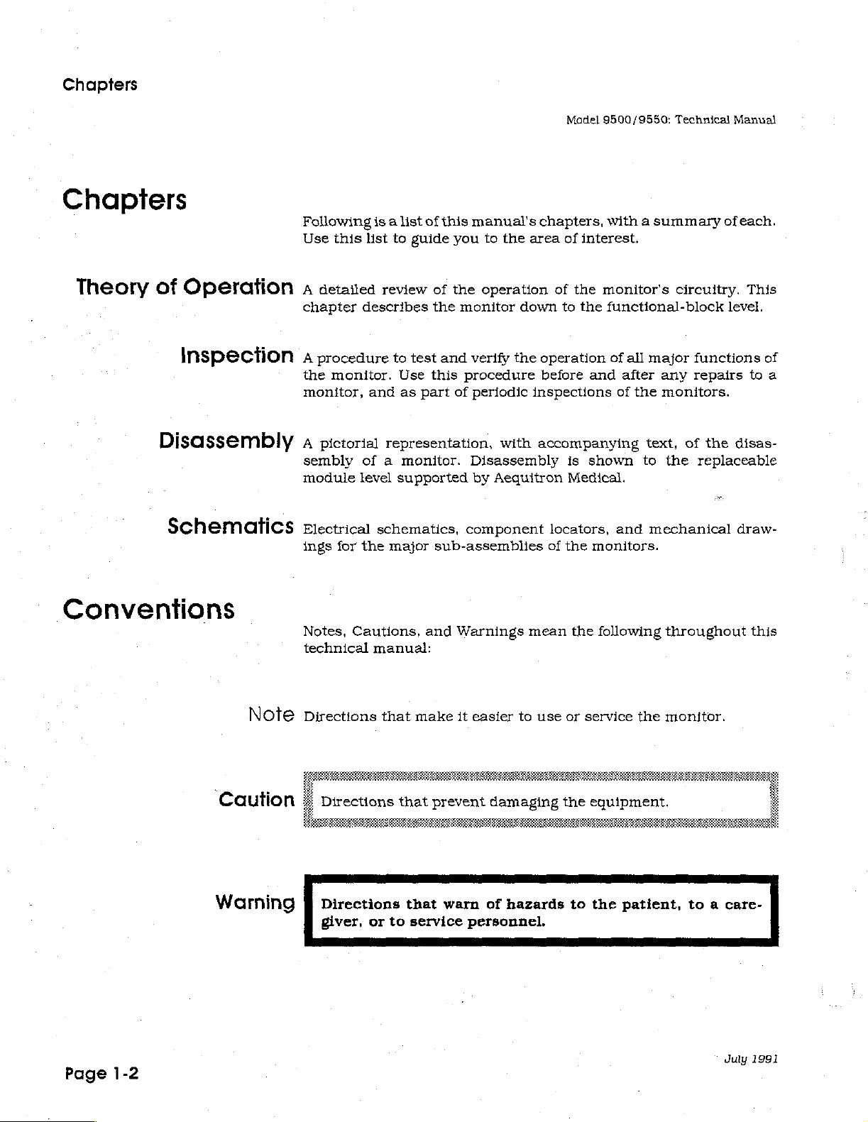
Note
Warning
Directions
Directions
that
that
make
prevent
JÍ
Directions
giver,
or
that
to
warn
service
it
easier
damaging
of
hazards
personnel.
to
use
or
service
the
equipment.
to
the
the
monitor.
a
patient,
to a care-
duly
1991
Description
The
light
one
for
each
The
monitor
on
alarm
monitor
sounds a warning
the
front
panel
can
occur
alarm.
sounds
to
at
the
alarms
alarm
indicate
same
when
which
time.
it
and
turns
alarm
In
this
detects:
on
the
appropriate
occurred.
case, a light
More
than
turns
on
« A long
« A heart
*
An
equipment
Your
monitor
breathing
problem
The
front
+
Lights
*
RESET
*
POWER
e
Patient
+
Green
e
Alarm
pause
rate
is a warning
or
heart
is,
but
panel
for
button
switch
lights
speaker
in
the
that
problem
rate.
YOU
has:
human
cable
patient's
is
too fast
It
must
and
jack
for
breathing
breathing
or
system.
sounds
take
the
equipment
too
slow
It
does
an
alarm
necessary
effort
effort
not
and
alarms
and
prevent
indicates
action.
heart
problems
beat
where
with
the
July
1993
The
back
panel
+
Battery
+
Green
«
Otherjacks
has:
charger
charger
and
jack
light
controls
for
your
doctor
or
homecare
dealer
Page
2-1
Front
Panel
Model
9500/9550:
Technical
Manual
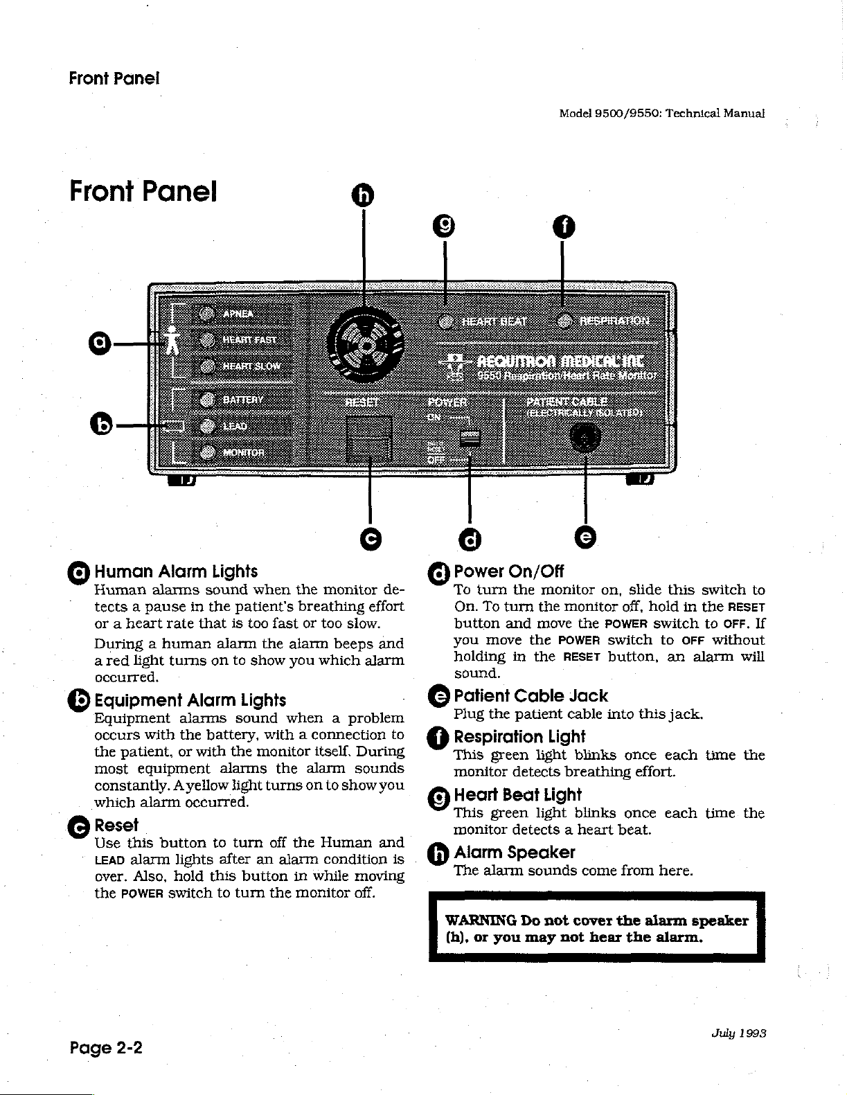
Front
Human
Human
tects a pause
or a heart
During a human
ared
occurred.
©
Equipment
Equipment
occurs
the
most
constantly. A yellow
which
©
Reset
Use
LEAD
over.
the
Panel
Alarm
alarms
light
with
patient,
equipment
alarm
this
alarm
Also,
POWER
rate
button
switch
sound
in
the
that
turns
Alarm
alarms
the
battery,
or
with
occurred.
lights
hold
this
Lights
when
patient's
is
too
alarm
on
to
show
Lights
sound
the
monitor
alarms
light
to
turn
after
an
button
to
turn
©
the
monitor
breathing
fast
or
too
the
alarm
you
which
when a problem
with a connection
itself.
the
alarm
turns
on
to
off
the
Human
alarm
the
condition
in
while
monitor
effort
slow.
beeps
alarm
During
sounds
show
moving
off.
de-
and
to
you
and
is
©
Power
To
turn
On.
To
button
you
move
holding
sound.
©
Patient
Plug
the
Respiration
This
monitor
©
Heart
This
monitor
@
Alarm
The
alarm
On/Off
the
monitor
turn
the
and
move
the
POWER
in
the
Cable
patient
Light
green
green
light
detects
Beat
Light
light
detects a heart
Speaker
sounds
©
on,
monitor
the
RESET
Jack
cable
blinks
breathing
blinks
POWER
come
off,
switch
button,
into
beat.
from
slide
hold
switch
this
once
effort.
once
this
in
to
OFF
an
jack.
each
each
here.
switch
the
to
without
alarm
time
time.
RESET
OFF.
will
the
the
to
If
Page
2-2
WARNING
(h),
or
you
Do
may
not
not
cover
hear
the
the
alarm
alarm.
speaker
July
1993
Model
9500/9550:
Technical
Manual
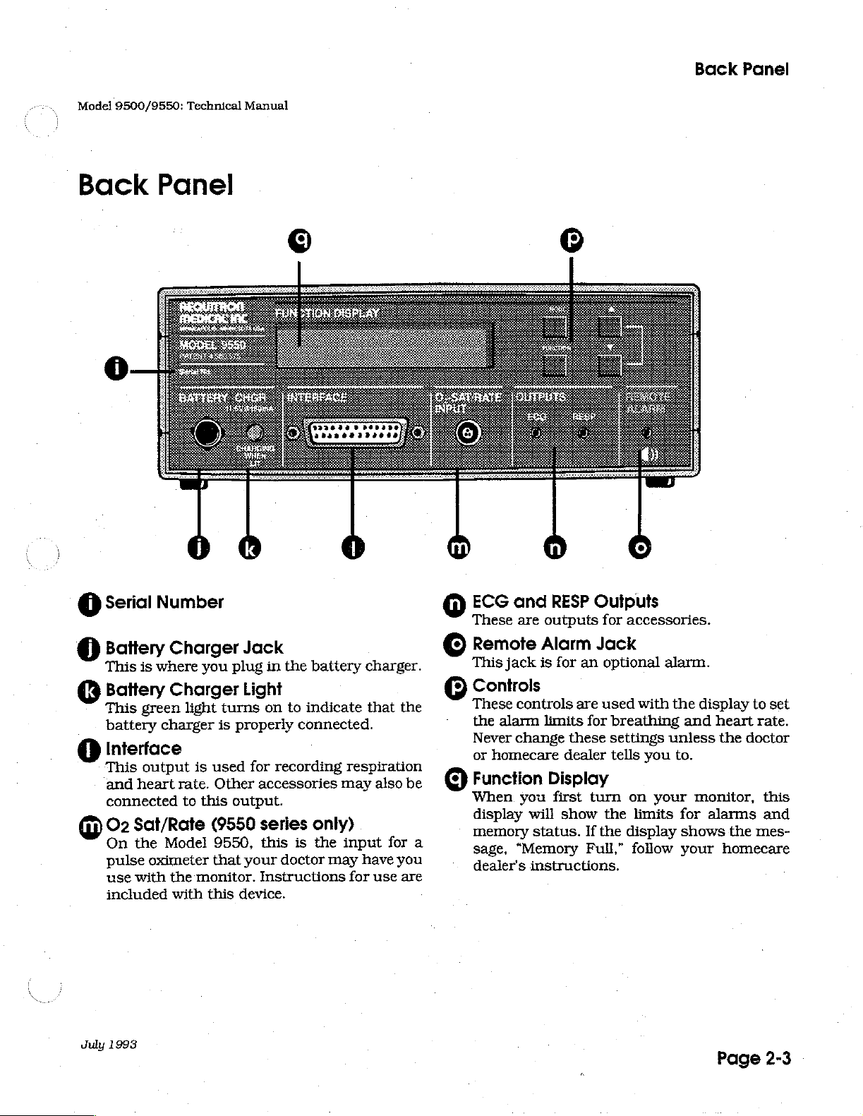
Back
Panel
Back
Panel
3329249360220
200004220004
Serial
@
Battery
This
Battery
This
battery
Interface
This
and
connected
O2
©
On
pulse
use
included
Number
Charger
is
where
Charger
green
heart
Sat/Rate
the
with
light
charger
output
rate.
to
Model
oximeter
the
with
is
monitor.
you
turns
is
used
Other
this
(9550
9550,
that
this
Jack
plug
in
Light
on
properly
for
recording
accessories
output.
series
this
your
doctor
Instructions
device.
the
battery
to
indicate
connected.
only)
is
the
may
charger.
that
the
respiration
may
also
be
input
have
for
for
use
you
are
ECG
©
These
©
Remote
This
Controls
These
the
Never
or
©) Function
When
display
a
memory
sage,
dealer's
and
are
Alarm
jack
is
controls
alarm
homecare
limits
change
you
will
status.
“Memory
instructions.
RESP
outputs
Outputs
for
Jack
for
an
optional
are
used
for
these
dealer
Display
first
turn
show
the
If
the
Full,”
accessories.
alarm.
with
the
breathing
settings
tells
unless
you
on
your
limits
display
follow
to.
display
and
heart
monitor,
for
alarms
shows
your
to
rate.
the
doctor
this
and
the
mes-
homecare
set
July
1993
Page
2-3
Accessories
Accessories
These
signals
accessories.
accessories
and
carry
pick
them
up
to
the
your
Model
patient's
monitor.
9500/9550:
breathing
Use
only
Technical
and
Aequitron
Manual
heart
approved
beat
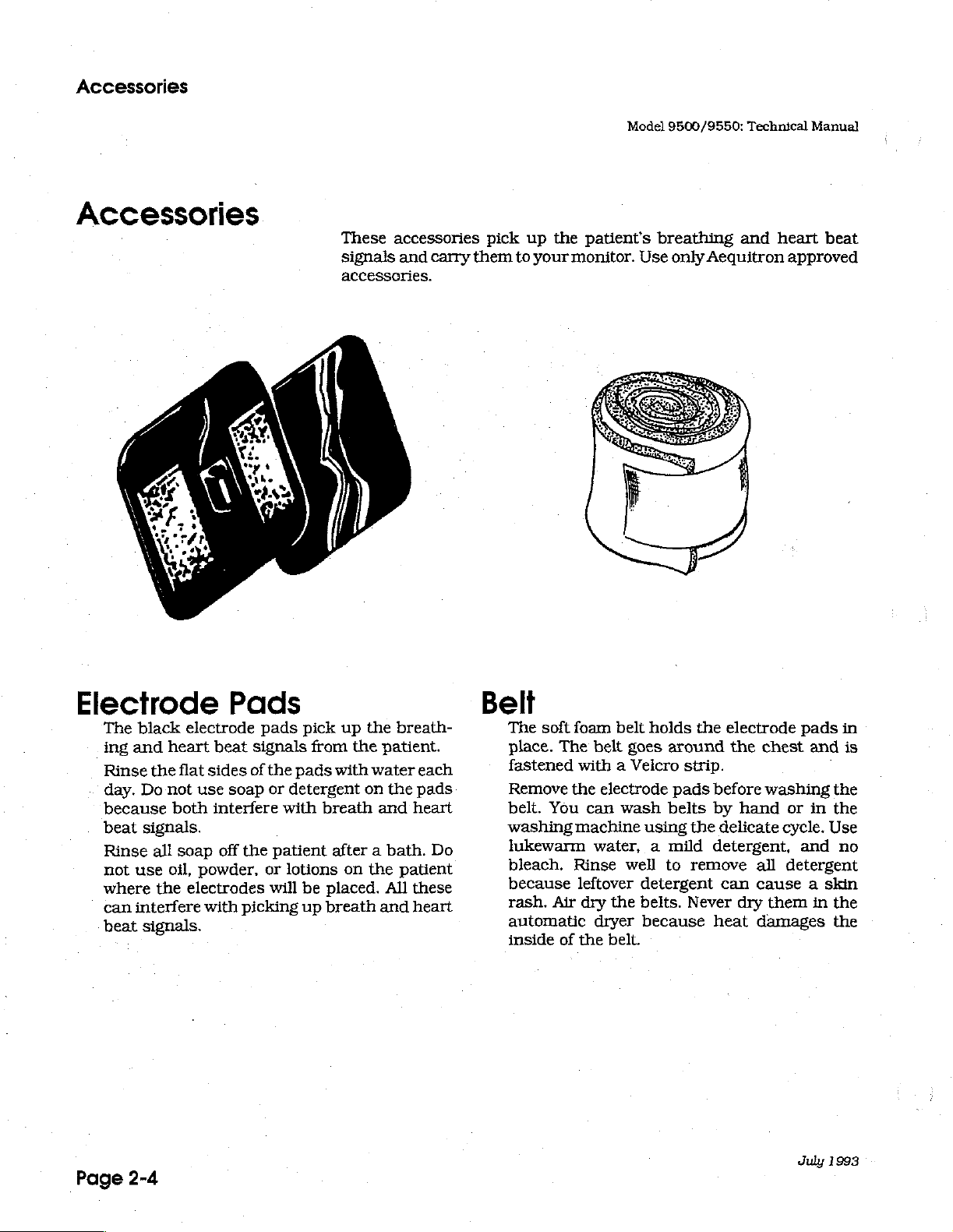
Electrode
The
ing
Rinse
day.
because
beat
Rinse
not
where
can
beat
Page
black
and
use
interfere
2-4
electrode
heart
the
flat
Do
not
both
signals.
all
soap
oil,
the
electrodes
signals.
Pads
beat
signals
sides
of
use
soap
interfere
off
the
powder,
with
picking
pads
the
pads
or
detergent
with
patient
or
lotions
will
pick
up
from
the
with
breath
after a bath.
on
be
placed.
up
breath
the
breath-
patient.
water
on
the
and
the
patient
All
and
each
pads
heart
Do
these
heart
Belt
The
soft
place.
fastened
Remove
belt.
washing machine
lukewarm
bleach.
because
rash.
automatic
inside
The
the
You
Air
of
foam
belt
holds
belt
goes
with a Velcro
electrode
can
wash
using
water, a mild
Rinse
leftover
dry
dryer
the
well
detergent
the
belts.
because
belt.
the
around
strip.
pads
before
belts by
the
detergent,
to
remove
Never
heat
electrode
the
chest
washing
hand
delicate
all
can
cause a skin
dry
them
damages
pads
in
and
the
or
in
the
cycle.
Use
and
no
detergent
in
the
the
July
1993
is
Model
9500/9550:
Technical
Accessories
Manual
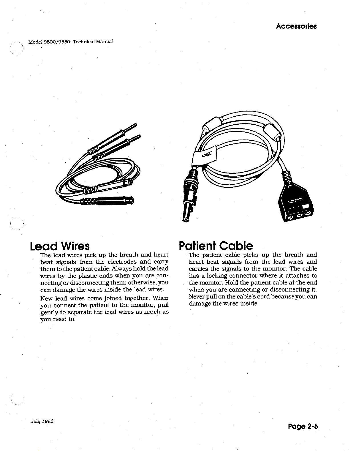
Lead
The
beat
them
wires
necting
can
New
you
gently
you
Wires
lead
wires
signals
to
the
by
the
or
disconnecting
damage
lead
wires
connect
to
separate
need
to.
pick
from
patient
plastic
the
wires
come
the
patient
up
the
the
electrodes
cable.
ends
inside
joined
the
lead
breath
Always
when
them;
the
to
the
wires
and
and
hold
the
you
are
otherwise,
lead
wires.
together.
monitor,
as
much
heart
carry
lead
con-
you
When
pull
as
Patient
The
patient
heart
carries
has a locking
the
when
Never
damage
beat
the
monitor.
you
pull
the
Cable
cable
signals
signals
Hold
are
on
wires
picks
to
connector
the
connecting
the
cable’s
inside.
from
the
patient
up
the
the
lead
monitor.
where
or
cord
it
cable
disconnecting
because
breath
wires
The
cable
attaches
at
the
you
and
and
to
end
it.
can
duly
1993
Page
2-5

Model
9500/9550:
Technical
Manual
Page
2-6
July
1991
Theory
of
Operation
monitors
The
detects
Human
logged.
recorded.
oxygen
pulse
The
It
rails. A watchdog
and
The
analog
phone
plug
For
power
system.
The
current
atory
signals,
tions,
and
desaturations
oximeter.
monitor
also
has
is
executing
monitor
board,
jack
into
this
system,
isolated
for
signals.
detects
are
alarms
events,
Trend
The
9550
has
circuitry
consists
the
board and
the
back
theory,
the
The
power
section
respiration
The
and
digitizes
events,
intended
for
equipment
and
waveform
series
when
an
audible
which
circuit
the
software
of
digital
panel
we
will
isolated
system
provides
analog
and
for
use with
central
ensures
five
board,
key
divide
detection,
them.
apnea,
alarms
monitors
used
alarm
detects
program
separate assemblies:
switch
board.
the
section,
provides
section
The
stores
and
data
also
in
conjunction
(minimum
the
that
the
the
back
board
monitor
the
the
patient
and separates
processes
digital
data.
infants
tachycardia
monitor
for
human
detect,
loss
microprocessor
correctly.
panel,
analog
power
isolation,
section
of
are
into
the
any
record
of
and
separate
four
system,
rails
the
ECG
through
and
on/off
events
with
79
dB(A)
or
all
the
front
the
main
and
for
supplies
ECG
and
performs
adults.
bradycardia.
times
and
an
at 2 feet).
of
the
is
panel,
battery.
boards
parts:
the
the
and
respiratory
are
are
also
validate
external
power
running
the
The
that
the
digital
monitor.
the
drive
respir-
calcula-
It
July
1991
Refer
to
the
letters
is
panel,
A, D,
located: A =
and F =
Block
Diagram
R,
and F indicate
analog
front
panel.
on
page
the
board, D =
3-9.
board
digital
On
the
block
where
the
board, R =
diagrams,
particular
rear
(or
Page
the
circuit
back)
3-1
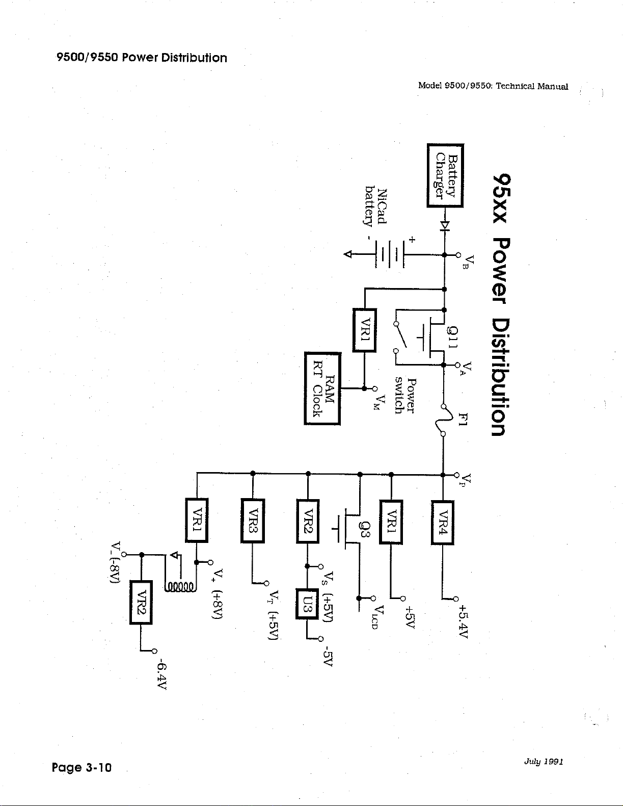
Power
System
Model
9500/9550:
Technical
Manual
Power
System
Refer
to
the
Block
The
Model
provides
is
provided
from
damaging
(greater
microprocessor.
The
battery
nected
charged
operate
can
be
The
battery
(Q11
and
Va.
Va
monitor
without
of
the
side
of
continuous
9271
11.6
through
than
in
series.
battery voltage
up
to
recharged
voltage,
the
powers
(and
holding
circuitry
the
fuse
power
Diagram
battery
VDC
at
diode
the
device.
+15
V)
consists
three
It
days
in
of
is
rated
about
VB,
front-panel
the
alarm
set
off
the
in
the
from
excessive
is
called
to
the
on
charger
180
mA. The
CR1,
The
from
damaging
eight
at
is
between
on a fully
18
hours.
passes
POWER
circuitry.
alarm)
RESET
switch.
current.
Vp.
RAM
page
3-10.
is a three-prong
charging
which
tranzorb,
prevents a shorted
Z1,
prevents
the
unit
nickel-cadmium
2000
mAH
(milli-amp
11
and
12
VDC.
charged
through a parallel
switch),
911
if
the
Vm
is
chips
battery
after
will
POWER
The
fuse,
The
derived
and
real
maintain
voltage
from
time
(or
operating)
or
(NiCad)
The
alone.
which
switch
F1,
protects
on
VB
clock.
charger
input
voltage
resetting
cells
hours).
monitor
The
set
of
switches
it
is
known
power
is
turned
the
protected
and
provides
that
current
jack
spikes
the
con-
Fully
will
battery
as
in
the
off
the
rest
Vp
provides
+5.4 V for
analog
Note
back
back
Oscillator
30
has a 50%
of
that
panel
diodes)
kHz.
Tl.
section.
circuit
The
Tl
rectified by
section
patient
where
signal.
the
voltage
the
Holter-type
Vp
ground
board.
on
the
U4
is
an
frequency
duty
cycle.
provides
CR12.
it
is
regulated
They
analog
astable
is
This
the
T1
also
provides
for
the
various
recorder,
and
chassis
are
also
+5 V supplies,
down
to
ground
connected
board.
multivibrator
set
by
R34
and
signal drives Q 1
negative
couples
the
voltage
the
power
regulators
Vs
(+5
operating
C19.
which
V-,
30
kHz
and
carrier
V+
V)
by
are
tied
together
at
The
drives
filtered
through
frequency
in
the
monitor:
and
V-
VR2.
together
(with
back-to-
approximately
output
by
to
at
the
C30
the
primary
isolated
for
on
U4-10
and
for
the
the
the
Page
3-2
July
1991
Model
9500/9550:
Technical
Manual
Isolated
Section
Isolated
Section
Power
by T1.
develops
isolated
negative
Resistors
(CR14
ly + 10
the
imately
patient
for
The
the
positive
power
and
VDC.
patient
50 uA.
impedance
the
diodes,
positive
R64
CR15),
drive.
isclated
CR16-CR19,
power
rail
is
and
R63
These
C39
and
R65
Since
(typically
section
and
negative
rail
filtered
limit
diodes
C40
and
R65
and
is
the 30
block
R66
500
essentially a constant-current
patient
RA
appear
voltage
2
small
impedance
amplitude-modulates
R78,
instrumentation
protection
the
and
mV
R79
patient
impedance
LA.
The
across
source
in
amplitude.
change
of
and
to
or
amplitude-modulate
respiration-modulated
R67.
The
patient
within
in
the
The
impedance
500
to
patient
respiration
1000
the 30
diodes
the
to
CR23-CR30
amp.
circuitry
the
Surge
patient
if
an
cable
is
derived
form a full-wave
power
filtered
by
R70
set
limit
R66
to
for
by
and
kHz
current
the
drive
any
low
the
are
significantly
1000
source.
30
ECG
signal
generating
signal
(0.2
to 3 ohms)
ohms.
kHz
arrestors
electrostatic
The
carrier
provide
input.
from
the
the
isolated
R71
and
C41.
C38.
for
voltage
frequency
patient
ohms),
current
the
Therefore,
the
30
KHz
kHz
signal
can
be
signals
can
be
out
change
signal.
input
El, E2,
discharge
30
kHz
provided
rectifier,
section.
The
isolated
the
zener
to
approximate-
modulation
to
approx-
larger
than
patient
changes
voltage
and
the
thought
between
thought
of a total
in
impedance
protection
and
E3
is
delivered
which
The
diodes
the
drive
in
the
across
ECG
of
as
0.1
and
of
as
body
to
the
provide
of
is
a
a
to
July
1991
The
instrumentation
extremely
the
ECG
C33 and
modulated
signal.
C36
T2
blocks
low-pass
signal.
provides
92
carrier
ofthe
between
build-up.
U8-12,13,14
and
for
analog
amp
high
input
impedance,
and
respiratory
R56
form a high
30
kHz
signal
couples
DC
filter.
the
while
This
respiration
the
filters
provides a gain
low-pass
93
provide a full-wave
the
isolated
filtering
ECG
board.
and
signal.
R57
U8
(pins
with a differential
signal.
pass
filter.
to
the
primary
signal
network
out
the 30
with
an
chopper
T3
couples
and
R39
form a high
non-isolated
1,2,3,
This
of
L1,
kHz
of
fe
of
it
grounds
5,6,7,
couples
of
T2
to
the
R74
carrier
about
100
(at
30
to
the
8,9,10)
gain
the
and
blocks
non-isolated
and
C87
leaving
nine,
Hz.
kHz)
that
non-isolated
impedance
to
limit
offset
provides
of 5 for
respiration-
the
provides
the
while
acts
an
both
ECG
section.
ECG
C35
as
the
section
connection
voltage
Page
3-3
a
Analog
System
Model
9500/9550:
Technical
Manual
Analog
System
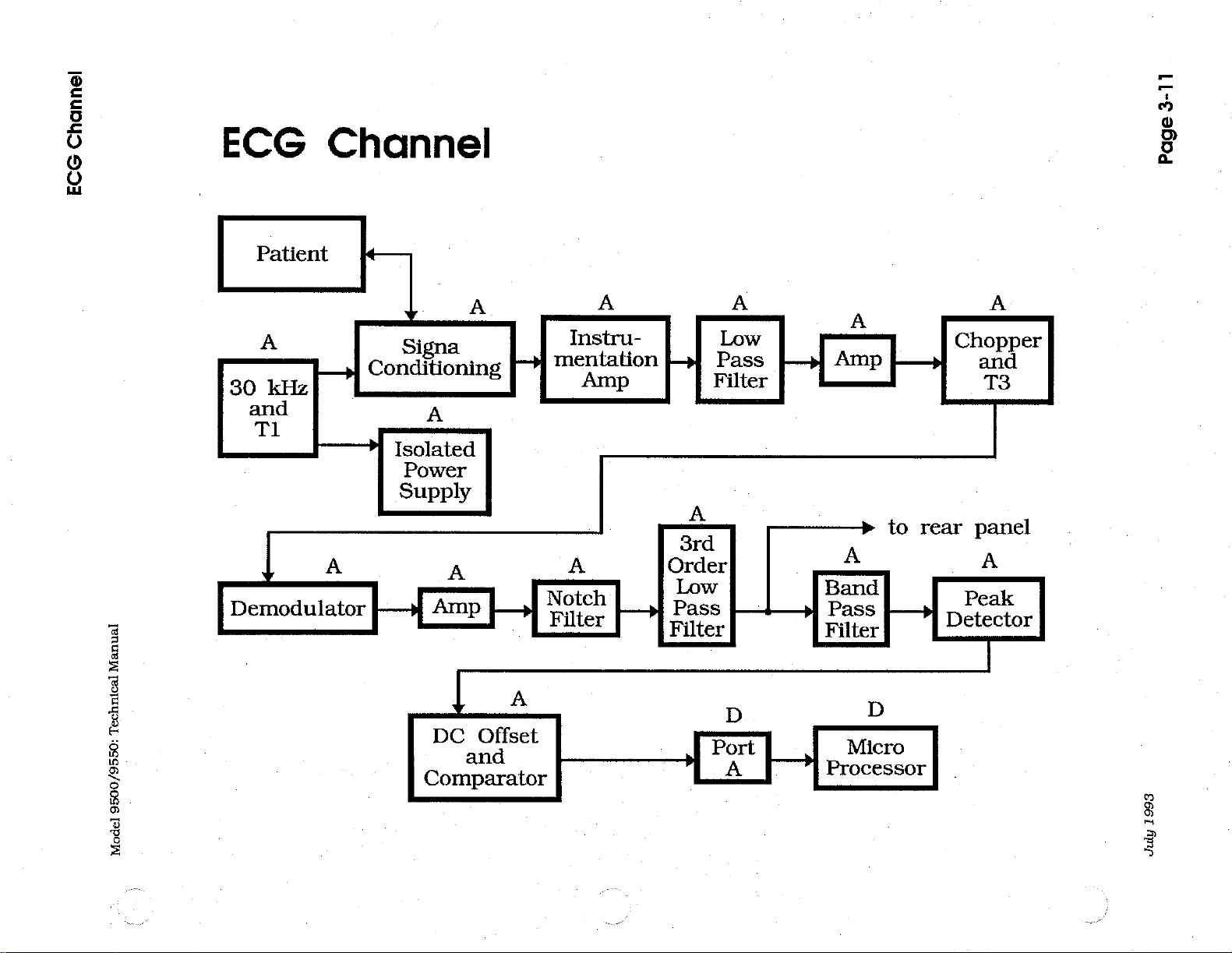
ECG
Channel
The analog
and,
in
the
processes
the
monitor's
Refer
to
the
R35 and
be
controls
filtered
U6-1,2,3
table
DC
used
(R40
via
offset
C21
to
analog
provides
R93.
for
U6-12,13,14
12,13,14
60
12,13,14
U6-1.
signal
AC
two
is a bandpass
Hz
with
is
U6-5,6,7
at
50
line-frequency
signals.
system
9550
series,
the
ECG
outputs
Block
Diagram
provide a 90°
demodulate
switch
and
C22),
variable,
C42
rolls
the
rest
and
U6-5,6,7
R94
acting
180°
out-of-phase
sums
or
60
Hz)
noise.
consists
and
and
of
the
oximeter
respiratory
the
on
phase
the
ECG
U5-3,4.
and
DC
non-inverting
the
signal
of
the
ECG
form a line-frequency
filter
whose
as
the
the
signals
to
provide a signal
R92
the
ECG
digital
page
shift
signal.
The
ECG
blocked
off at
channel.
tuning
with
from
is
used
and
channel.
signals.
system's
3-11.
in
the
signal
(C23).
gain
about
passband
element.
the 50
U6-1
to
adjust
respiration
The
It
supplies
inputs.
30
kHz
The
demodulator
is
from
50
can
The
or
60
and TP9
at
TP10
the
channels,
analog
signals
signal
so
demodulated
13
to
31,
Hz.
R95
notch
be
filter.
tuned
output
Hz
noise
signal
(the
that
has
summing
system
for
it
can
signal
and
adjus-
sets
the
U6-
to
50
or
of
U6-
at
inverted
limited
of
the
Page
3-4
U6-8,9,10
Butterworth
about
Interface
divided
J5
U7-1,2,3
with
will
or
U7-8,9,10
will
voltages
voltage
40
Hz.
connector
by
(ECG
Low)
acts
gain
of
ring)
and
reversed.
pass
through
held
at
R56,
C44,
low
pass
The
R47
and
for
as a bandpass
about
will
detect
is a peak
on
C48
U7-10.
filter
output
(J5)
R46
use
by
24,
detector.
CR22
decay
R55,
C28,
with
of
this
through
and
again
Holter-type
filter
This
filter
heartbeats
Positive
and
off
R52
unity
section
R48 (ECG
sent
recorders.
(center
is
lightly
whether
be
held
through
and
C43
gain.
The
is
sent
High).
to
the
frequency
damped
RA/LA
voltages
on
the
R96
form a third-order
corner
Interface
(heartbeats)
capacitor
if
there
to
the
The
(i.e.,
leads
frequency
back
signal
connector
of
about
the
are
is
no
at
C48.
positive
July
is
panel
is
also
40
Hz)
output
correct
U7-8
The
1991
Model
9500/9550:
Technical
Manual
Analog
System
LEAD
Alarm
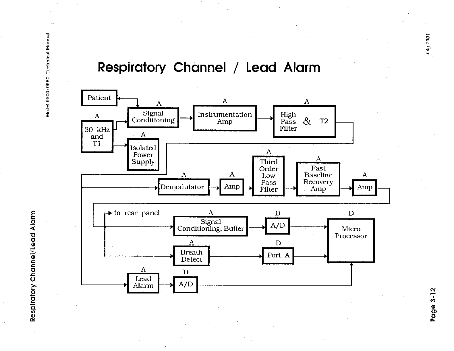
Respiration
Channel
U7-12,13,14
and
C5
filter
with
the
unfiltered
low
to
high
when a heartbeat
The
ECG
signal
J12-5
and
controls
microprocessor
Refer
U1-5,6,7
corresponds
is
Its
Nominally,
a
Refer
respiratory
provides
divided
then
lead
90°
phase
switch
to
the
Block
acts
to
by
R2
transmitted
patient
alarm.
to
the
Block
shift
signal.
U5-1,2.
non-inverting
and
V-
the
ECG
version
(high
receives
Diagram
as a peak
the
impedance
and
R104,
impedances
Diagram
in
the 30
The
R28
and
provide
signal
or
low)
the
gate
the
detector
over
kHz
demodulator
C14
gain
the
ECG
at
U3-2 such
at
U3-3.
is
detected.
arrives
of
Q1,
signal
on
page
across
then
sent
the
data
greater
on
page
signal . This
filter
of
gain
signal
with a DC
that
it
can
The output, U3-1,
on
the digital
which
via
its
data
is
board
fed
bus.
into
3-12.
providing a voltage
the
patient
to
input 3 of
bus
than
3-12.
is
signal
the
respiratory
of
about
to
the
1800
R35
used
controls
18.
leads.
the
A/D
microprocessor,
ohms
and
C21
to
demodulate
signal.
offset.
be
compared
changes
at
connector
Port
at
TP2
This
voltage
via
will
provide
the
U2-1,2,3
R23
from
A.
The
that
J12-6.
cause
the
analog
a
R11,
C13,
Butterworth
about 5 Hz.
U2-12,18,14
depending
CRI
and
CR2
these
going
swings
makes
CR2,
output
two
into
saturation,
in
its
large
and
the
(U2-14)
U2-8,9,10
recovery
cy
about 9 Hz.
of
amp
0.07
connector,
filtered
the
by
Interface
R15,
C16,
low-pass
provides
on
the
adjustment
are
5.1 V zener
diodes
and
output.
swings,
signal
from
functions
(U2-12,13,14).
Hz
and
R14
The
output
J5, via
the
R50
C24, C25,
connector,
R29,
C15
filter
with
unity
an
inverting
of
R20.
diodes.
R7
keeps
hence,
If
the
inversion
the
output
diodes
allowing
CR3
in
saturating.
as a bandpass
C12
and
C7
give
of
U2-8
goes
as
the
RESP
R30,
R32
J5
(Resp
and
U2-5,6,7
gain.
gain
of
The
the
voltage
it
to
recover
of
U2-7
and
CR4,
U2-12,13,14
filter
and
and
R9
give a lower
an
upper
out
to
High
signal.
network
Filtered).
form a third-order
The
corner
between
current
output
300
flowing
of
quickly
(between
the
C17
zeners
combine
as a buffer
corner
the
and
In
addition,
corner
back
panel
The
again
freguency
output
frequency
and
through
U2-14
from
and
from
large
R19)
CR1
to
keep
for
the
frequen-
Interface
also
goes
out
the
output
is
600,
and
the
fast
of
is
to
July
1991
Page
3-5
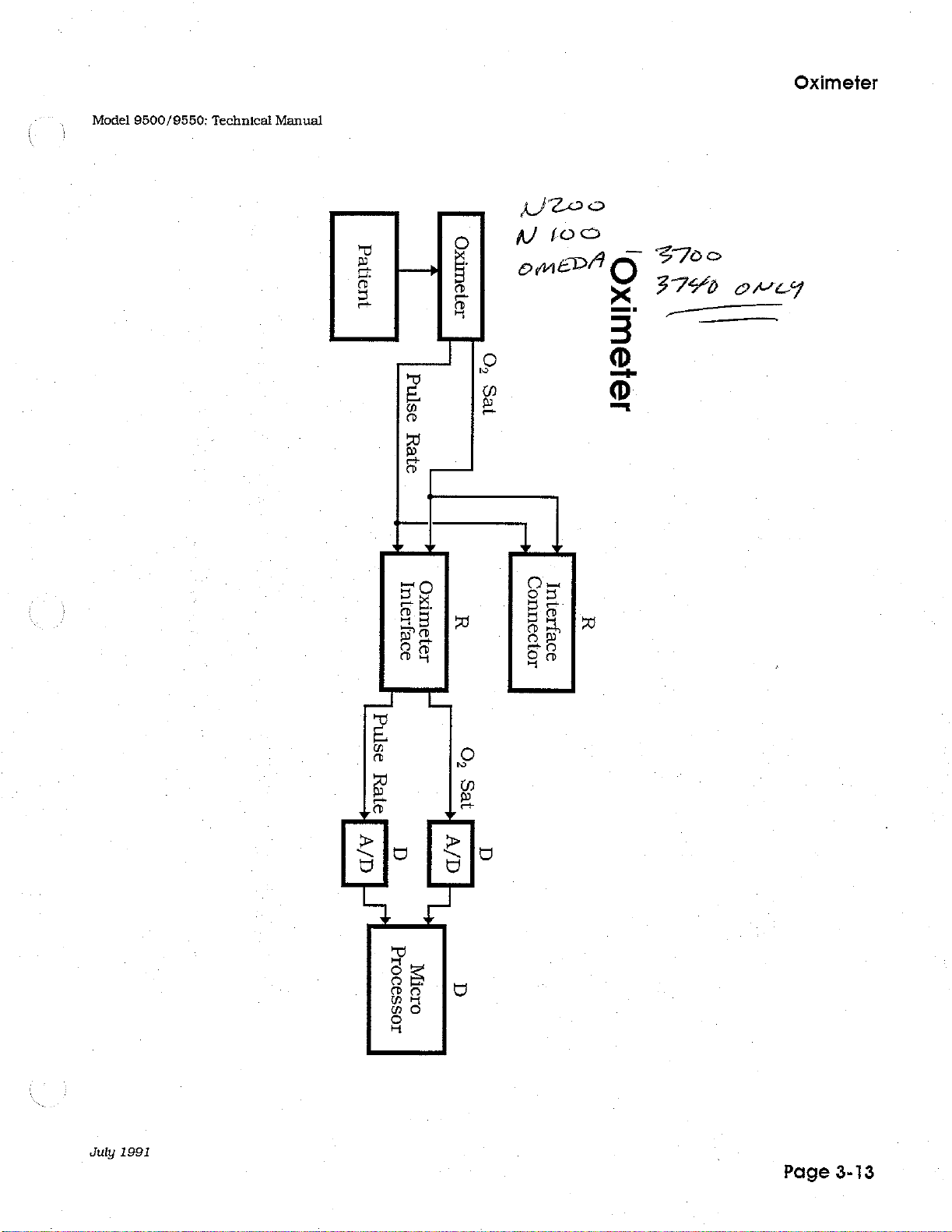
Digital
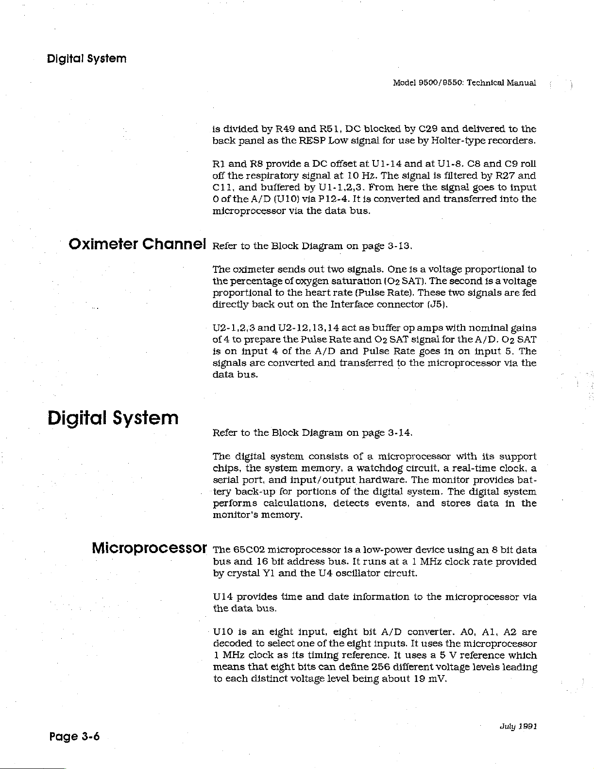
Oximeter
System
Channel
is
divided
back
R1
and
off
the
C11,
Oofthe
by
R49
panel
as
R8
provide a DC
respiratory
and
buffered
A/D
(U10)
microprocessor
Refer
to
the
Block
The
oximeter
the
percentage
proportional
directly
back
sends
to
out
the
via
of
the
and
R51,
RESP
signal
by
U1-1,2,3.
via
P12-4.
the
Diagram
out
oxygen
heart
on
the
DC
Low
signal
offset
at
at
10
It
data
bus.
on
two
signals.
saturation
rate
(Pulse
Interface
blocked
for
U1-14
Hz.
The
From
is
converted
page
3-13.
One
(O2
Rate).
connector
Model
9500/9550:
by
C29
use
by
and
at
signal
here
the
and
is a voltage
SAT).
These
Technical
and
delivered
Holter-type
U1-8.
is
C8
filtered
signal
goes
transferred
proportional
The
second
two
signals
(J5).
Manual
to
the
recorders.
and
C9
roll
by
R27
and
to
input
into
the
is a voltage
are
to
fed
Digital
System
Microprocessor
U2-1,2,3
of 4 to
is
prepare
on
input 4 of
signals
data
bus.
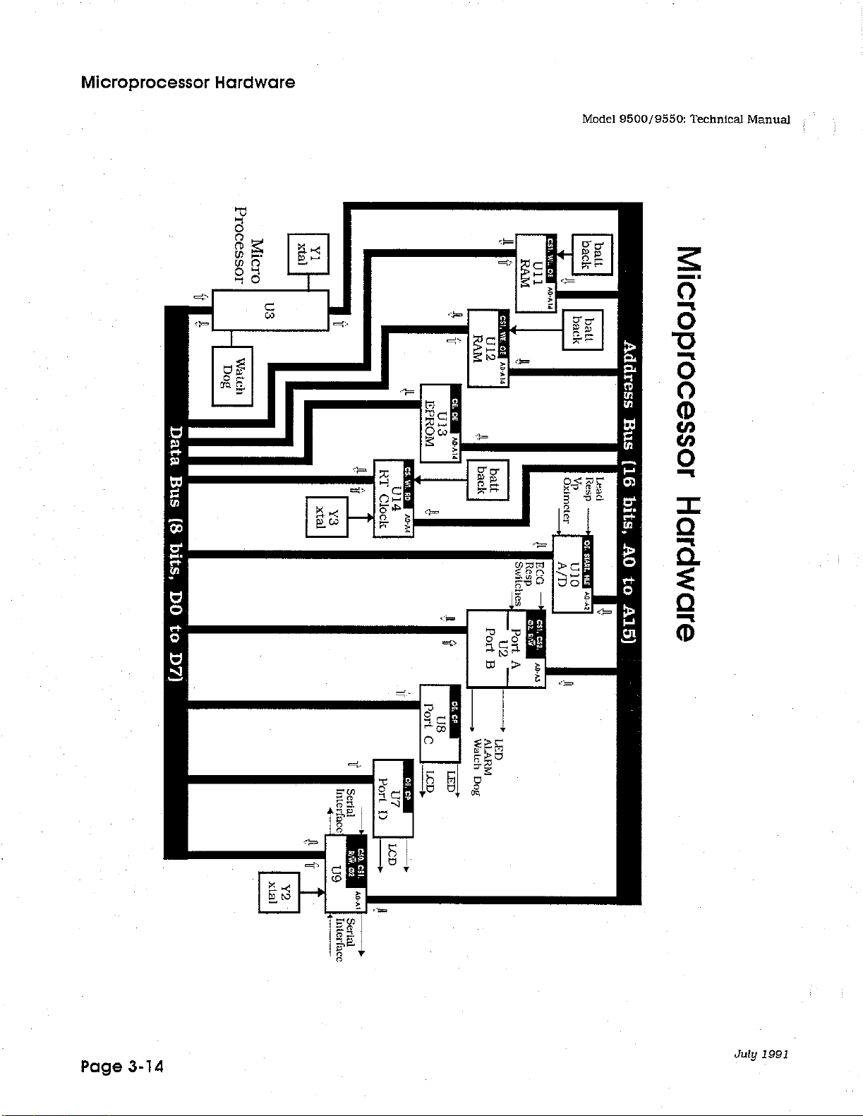
Refer
to
The
digital
chips,
serial
tery
the
port,
back-up
performs
monitor's
The
65C02
bus
and
by
crystal
U14
provides
the
data
and
U2-12,13,14
the
the
are
converted
the
Block
system
system
and
input/output
for
calculations,
memory.
microprocessor
16
bit
address
Y1
and
time
bus.
act
as
buffer
Pulse
Rate
and
O2
A/D
and
Pulse
and
transferred
Diagram
consists
on
page
of a microprocessor
memory, a watchdog
hardware.
portions
the
and
of
detects
is a low-power
bus.
U4
oscillator
date
the
digital
events,
It
runs
information
op
amps
with
SAT
Rate
to
the
signal
for
goes
in
microprocessor
3-14.
circuit, a real-time
The
monitor
system.
and
device
at a 1
MHz
The
stores
using
clock
circuit.
to
the
microprocessor
nominal
the
on
with
provides
digital
rate
A/D.
O2
input
5.
via
its
support
clock,
system
data
in
an 8 bit
provided
gains
SAT
The
the
a
bat-
the
data
via
Page
3-6
U10
is
decoded
1
MHz
means
to
each
an
eight
to
select
clock
as
that
eight
distinct
input,
one
of
its
timing
bits
can
voltage
elght
the
eight
reference.
define
level
being
bit
A/D
inputs.
256
converter.
It
uses
the
It
uses a 5 V reference
different
about
19
voltage
mV.
AO,
Al,
A2
are
microprocessor
which
levels
leading
duly
1991
Model
9500/9550:
Technical
Manual
Digital
System
Memory
Watchdog
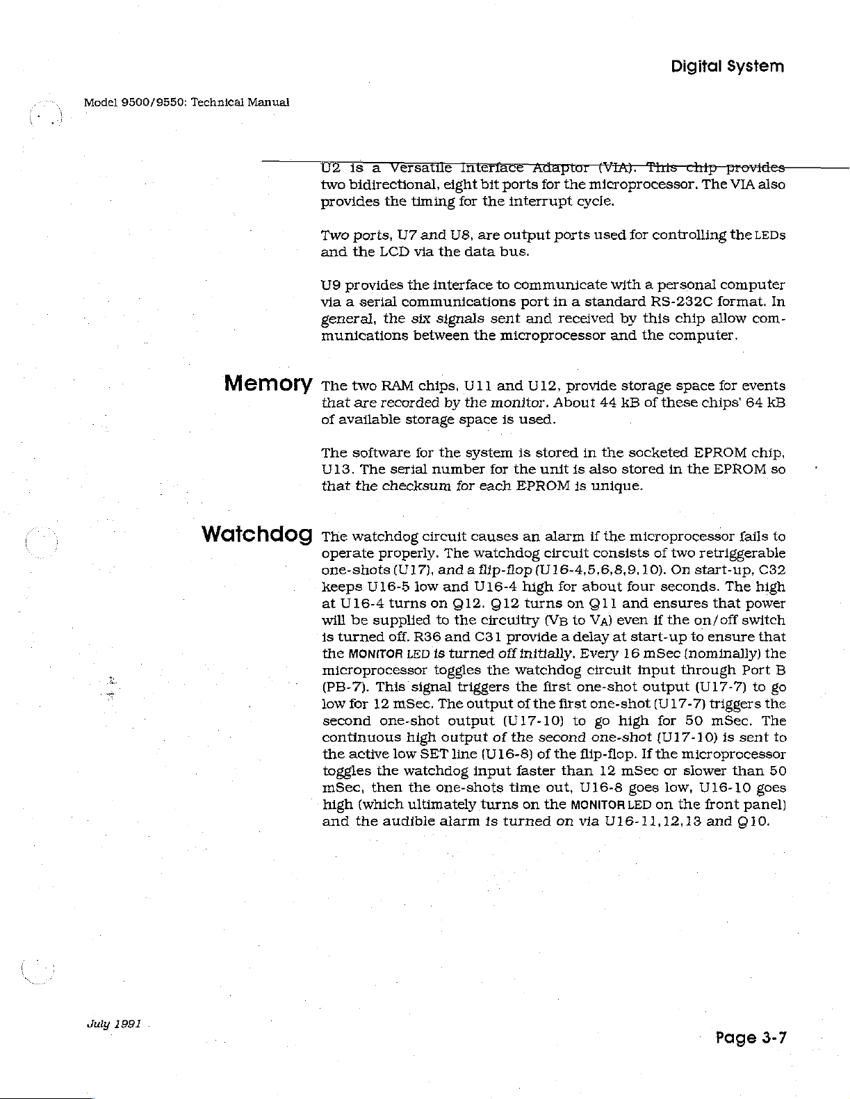
U2
is a Versatile Interface
two
bidirectional,
provides
Two
and
U9
via a serial
general,
the
ports,
the
LCD
provides
the
U7
munications
The
two
RAM
that
are
recorded
of
available
The
software
U13.
The
serial
that
the
checksum
The
watchdog
operate
one-shots
keeps
at
will
is
the
microprocessor
(PB-7).
low
second
U16-5
U16-4
be
turned
MONITOR
for
properly.
(U17},
turns
supplied
off.
This
12
mSec,
one-shot
continuous
the
active
toggles
mSec,
high
and
the
then
(which
the
audible
low
communications
eight
timing
and
U8, are
via
the
the
interface
six
signals
between
chips,
by
storage
for
the
number
circuit
The
and a flip-flop
low
and
on
to
R36
and
LED
is
turned
toggles
signal
The
output
high
output
SET
line
watchdog
the
one-shots
ultimately
alarm
bit
for
the
data
to
sent
the
U1]
and
the
monitor.
space
system
for
for
each
causes
watchdog
U16-4
Q12.
Q12
the
circuitry
C31
off
the
triggers
output
of
(U16-8)
input
turns
is
Adaptor
ports
for
the
microprocessor,
interrupt
output
bus.
communicate
port
and
cycle.
ports
in a standard
received
microprocessor
U12,
provide
About
is
used.
is
stored
the
unit
EPROM
an
in
is
js
alarm
circuit
also
unique.
if
(U16-4,5,6,8,9,
high
for
about
turns
provide a delay
initially,
watchdog
the
of
(U17-10)
the
faster
time
on the
turned
(VB
first
the
first
second
of
the
than
out,
on
on
Q11
to
VA)
Every
circuit
one-shot
one-shot
to
one-shot
flip-flop.
U16-8
MONITOR
via
СУБ).
used
44
the
the
consists
This
for
controlling
with a personal
RS-232C
by
this
and
the
storage
kB
of
these
socketed
stored
microprocessor
of
10).
four
seconds.
and
ensures
even
if
the
at
start-up
16
mSec
input
output
(U17-7)
go
high
for
(U17-10)
If
the
12
mSec
U16-11,12,13
goes
LED
or
low,
on
chip
provides
The
VIA
the
computer
format.
chip
allow
computer.
space
in
two
On
for
chips'
EPROM
the
EPROM
retriggerable
start-up,
The
that
on/off
to
ensure
(nominally)
through
(U17-7)
triggers
50
mSec,
is
sent
microprocessor
slower
than
U16-10
the
front
and
Q10.
also
LEDs
com-
events
64
kB
chip,
fails
C32
high
power
switch
that
the
Port
to
the
The
50
goes
panel)
In
so
to
B
go
to
July
1991
Page
3-7
Digital
System
Model
9500/9550:
Technical
Manual
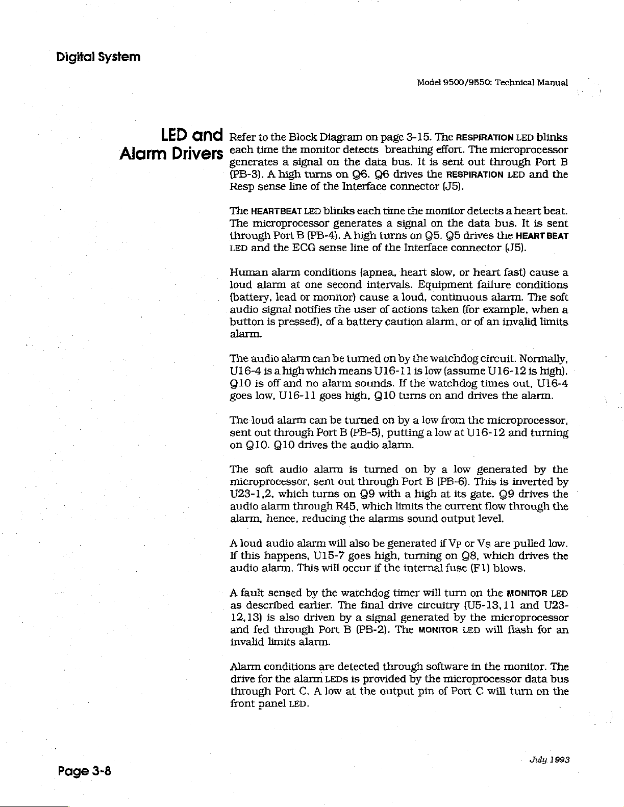
Alarm
LED
Drivers
and
refer
to
the
Block
Diagram
each
time
the
monitor
generates a signal
(PB-3). A high
Resp
sense
The
HEARTBEAT
The
microprocessor
through
LED
and
Human
loud
{battery,
audio
button
alarm.
The
U16-4
©10
goes
The
sent
on
alarm
signal
audio
is
low,
loud
out
Q10.
alarm
is
is a high
off
turns
line
of
the
LED
blinks
Port B (PB-4). A high
the
ECG
sense
conditions
at
one
lead
or
monitor)
notifies
pressed),
alarm
U16-11
alarm
through
Q10
and
can
which
no
alarm
goes
can
Port B (PB-5),
drives
on
page
3-15.
detects
on
the
on
Q6.
Interface
generates a signal
line
second
the
user
of a battery
be
turned
means
high,
be
turned
the
audio
breathing
data
bus.
Q6
drives
connector
each
time
the
turns
of
the
Interface
(apnea,
intervals.
cause a loud,
sounds.
heart
of
actions
caution
on by
U16-11
Q10
is
If
turns
on
by a low
putting a low
alarm.
The
effort.
It is
sent
the
(J5).
monitor
on
on Q5.
slow,
Equipment
continuous
taken
alarm,
the
watchdog
low
(assume
the
watchdog
on
from
RESPIRATION
The
microprocessor
out
through
RESPIRATION
detects a heart
the
data
bus.
Q5
drives
connector
or
(for
or
and
at
the
heart
failure
alarm.
example,
of
an
circuit.
U16-12
times
drives
the
microprocessor,
U16-12
LED
Port
LED
and
It
is
HEART
(J5).
fast)
cause
conditions
The
when
invalid
Normally,
is
out,
the
alarm.
and
turning
blinks
B
the
beat.
sent
BEAT
a
soft
a
limits
high).
U16-4
Page
3-8
The
soft
audio
microprocessor,
U23-1,2,
audio
alarm,
A
loud
If
this
audio
A
fault
as
described
12,13)
and
invalid
Alarm
drive
through
front
which
alarm
through
hence,
audio
happens,
alarm.
sensed
is
also
fed
through
limits
conditions
for
the
alarm
Port
panel
LED.
alarm
This
earlier.
alarm.
C. A low
alarm
sent
turns
reducing
U15-7
by
driven
Port B (PB-2).
is
out
on
R45,
the
will
also
goes
will
occur
the
watchdog
The
by a signal
are
detected
LEDS
is
at
turned
through
Q9
with a high
which
alarms
be
generated
high,
if
the
final
drive
through
provided
the
output
on
by a low
Port B (PB-6).
at
limits
timer
The
the
sound
turning
output
if
internal
will
circuitry
generated
MONITOR
current
Vp
on
fuse
turn
software
by
the
microprocessor
pin
of
Port
generated
This
its
gate.
flow
level.
or
Vs
Q8,
which
(F1)
on
(U5-13,11
by
the
LED
will
in
the
C will
by
is
inverted
Q9
drives
through
are
pulled
low.
drives
blows.
the
MONITOR
and
microprocessor
flash
monitor.
turn
for
data
on
July
LED
U23-
The
bus
1993
the
by
the
the
the
an
the
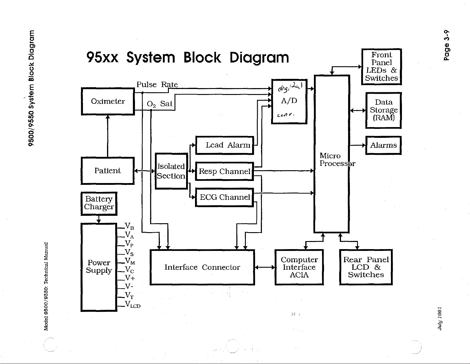
Diagram
95xx
System
Block
Diagram
Front
3-9
Page
Biock
System
9500/9550
Manual
Technical
|
Oximeter
:
|
Battery
Charger
4
m-
Patient
|
ГЕ
|
power
PY
|
Ey
ES
V-
ma
Pulse
| |
o,
‚| | {isolated
№
Va
Vp
V
Rate
sai
Section!
7
Interface
|
Resp
ECG
Connector
Lead
Channel-
Channel
-
Alarm
y
о
|
4—3]
>
dizi
A
lo
A/D
e
Computer
Interface
Ts)
in
>
」
ACIA
£
|
Micro
Processor
Е.
Rear
Switches
Switches
+i
>
LCD
LEDs
&
Data
Storage
(RAM)
Alarms
Panel
&
9500/9550:
Model
Vico
1991
July
9500/9550
Power
Distribution
Model
8500/9550:
Technical
Manual
RT
Clock
95xx
Power
Distribution
Page
<
3
3-10
VRI
y
一
+5V
+5.4V
July
1991
3-11
Channel
ECG
ECG
Channel
Isolated
Power
Supply
mentation
Instru-
Page
»
to
rear
panel
Manual
Technical
9500/9550:
Model
DC
Offset
and
Comparator
D
Port
Peak
Detector
1993
duly
Manual
1991
July
Technical
9500/9550:
Model
Alarm
Channel/Lead
Respiratory
>-
|
to
k
A
rear
»
Palient
A
30
KHz
and
Ti
A
Signal
Conditioning
A
isolated
Power
Supply
panel
А р
Lead
Alarm
|
Demodulator
Channel
4
»i
Conditioning,
"|
4
A/D
Instrumentation
FT?
A
A
Signal
A
Breath
Detect
/
Lead
A A
Amp
A
Third
Order
A
->|
Amp
Buffer
pass
Low
4
Alarm
À
High
Pass.
Filter
D D
A/D
Port
D
A
&
Baseline
Recove
>
A
Fast
‘Amp
T2
>
n
7
yi
Amp
Micro
Processor
A
3-12
Respiratory
Page
Model
9500/9550:
Technical
Manual
Patient
Pulse
Rate
Oximeler
I
O,
Sat
Oximeter
っ
Зо
991%
>
X
N
BO
m
ok
0
a
8
a
J
W
q
<
à
|
Oximeter
.
"|
Pulse
Rate
|
A/D
LP
Oximeter
Interface
U
Processor
Micro
R
|
O,
Sat
A/D
D
Connector
Interface
R
July
1991
Page
3-13
Microprocessor
Hardware
Processor
Micro
xtal
Model
9500/9550:
Technical
Manual
Microprocessor
(SSA
we,
o
[0200
Data
Bus
(8
bits,
DO
to
D7)
Vp
Oximeter
Lead
Resp
OE, STARI,
HLE
Bus
(16
bits,
AO
to
A15)
Hardware
Page
3-14
[+
Serial
Interface
»
July
1991
 Loading...