

Page 1

AEQ LIVE 20 TR
.
USER MANUAL
ED 05/07
Page 2

LIVE 20 TR USER’S MANUAL
1. LIVE 20 TR General description
1.1 General Description
1.2 Construction
1.3 Front panel description
1.4 FCC Compliance
1.5 Warning to Users
2. LIVE 20 TR Hardware
description
2.1 On/Off Switch
2.2 Display and channel selector
2.3 Audio input
2.4 TX Antenna connector
2.5 Low battery indicator
2.6 Audio level adjustment
2.7 Peak audio indicator
2.8 Power supply
2.9 Other connectors
3. LIVE 20TR Technical specifications
3.1 Technical characteristics
3.2 Mechanical specifications
4. ACCESORIES
5. CH-20 BATTERY CHARGER
5.1 General description
5.2 Front and rear view
5.3 Connection and starting to work
5.4 Indications
5.5 Characteristics
5.6 Protections
5.7 Connectors pin-outs
ANNEX 1 – Connector pin-out
ANNEX 2 – Security recommendations
A.E.Q. Warranty
AEQ LIVE 20 TR
.
2
Page 3
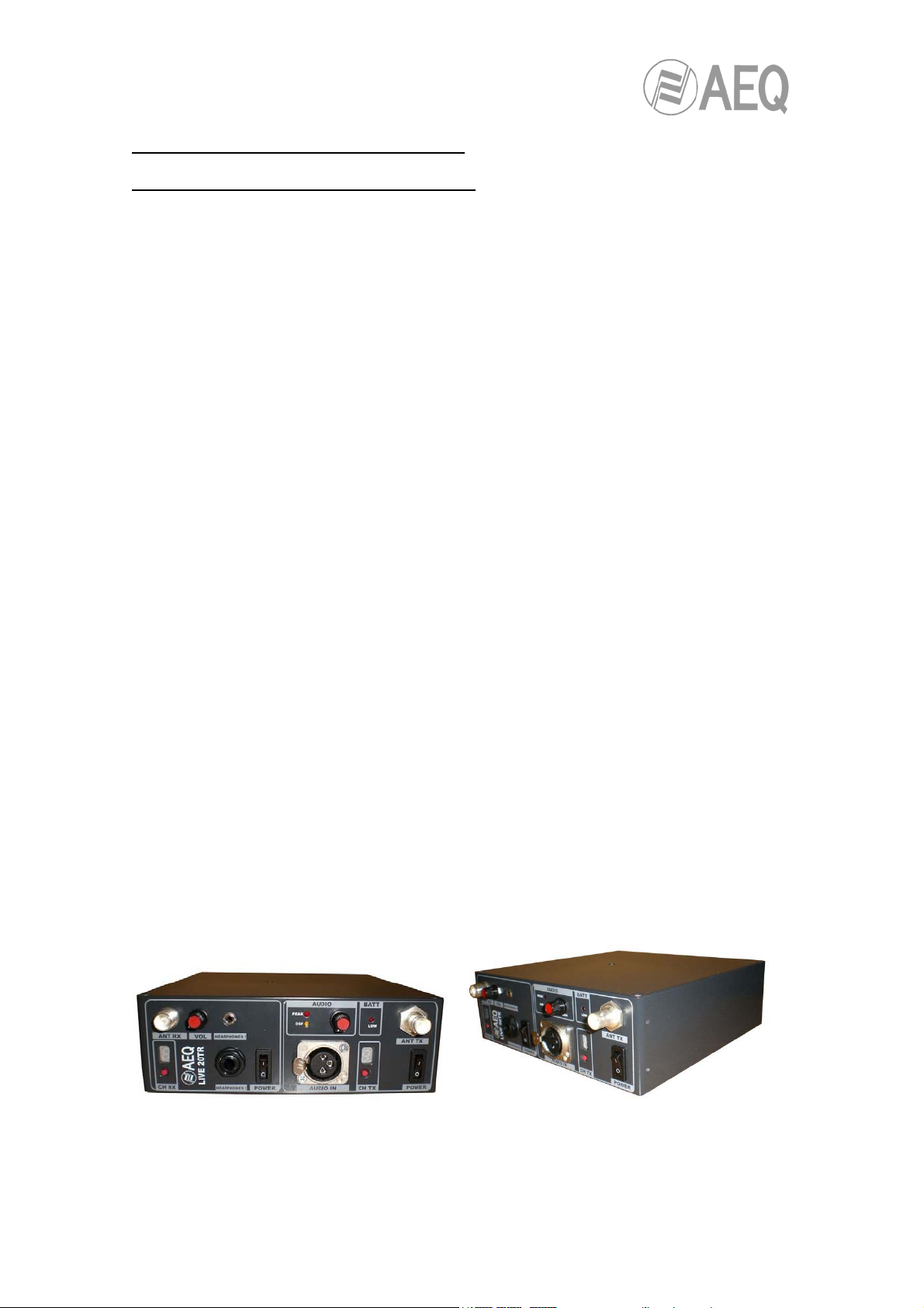
1. LIVE 20 TR GENERAL DESCRIPTION
1.1 LIVE 20 TR GENERAL DESCRIPTION
The AEQ LIVE 20 TR is a high specification FM transmitter for portable and
mobile service.
The signal generators together with the RF output module and the audio
processor forms a high quality transmitter capable of faithfully broadcasting
work in any situation. Transmit frequency are delivered in digital frequency
synthesizers and allow the selection of up to 16 pre-programmed channels.
The audio processor allows the use of dynamic microphones as well as line
level sources.
A mechanized aluminium enclosure assures outstanding mechanical stability
and immunity to interference and crosstalk.
In standard service the LIVE 20 TR is powered by a removable rechargeable
battery pack, which can be recharged in the unit as well. Also supplied with the
LIVE 20 TR is a ¼ wavelength centered antenna.
A 9 pin sub-D connector in the left side of the unit allows external
reprogramming.
AEQ LIVE 20 TR
.
3
Page 4
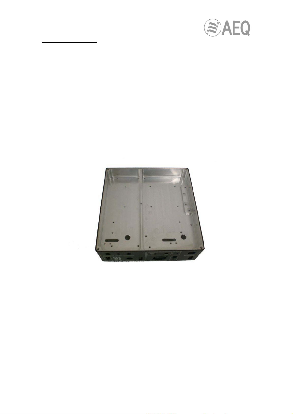
1.2 CONSTRUCTION
The boards of the AEQ LIVE 20 TR are made of epoxy glass fiber type FR4
with a thickness of 1,6 mm, 2 side type.
The AEQ LIVE 20 TR is equipped with Surface Mounted Devices (SMD) that
give the equipment a high grade of robustness.
If one SMD is damaged, the defective component should be replaced with a
new one.
Do not sense unsoldered components, even if they seem to be faultless.
AEQ LIVE 20 TR
.
4
Page 5
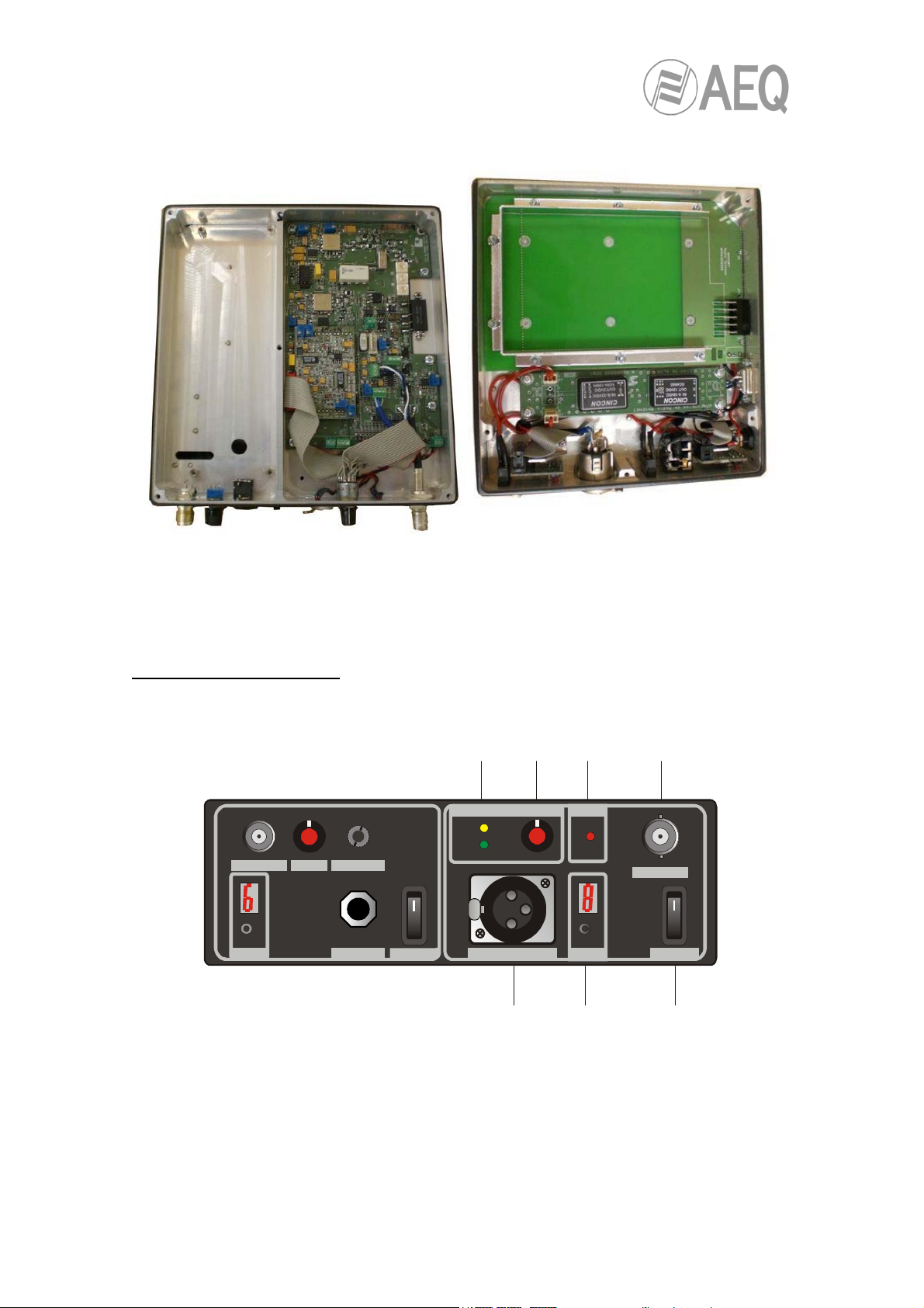
1.3 FRONT PANEL VIEW
ANT RX
AUDIO
PEAK
DSP
PHONES 1VOL
PHONES 2CH RX CH TX
GAIN
AUDIO IN
BAT
LOW
4567
ANT TX
OO
POWERPOWER
1123
AEQ LIVE 20 TR
.
5
Page 6

1.- ON/OFF switch
2.- Display and channel selector
3.- Audio input
4.- Tx antenna connector
5.- Low battery indicator
6.- Audio level adjustment
7.- Peak audio indicator
Note: The Rx section is not equipped
1.4 FCC Compliance
This device complies with part 15 of the FCC rules. Operation is subject to the
condition that this device does not cause harmful interface.
Any changes or modifications not expressly approved by the party responsible for
compliance could void the user’s authority to operate the equipment.
1.5 Warning to Users
Changes or modifications not expressly approved by the party responsible for
compliance could void the user’s authority to operate the equipment.
AEQ LIVE 20 TR
.
6
Page 7

2. LIVE 20 TR HARDWARE
2.1 ON/OFF SWITCH
To switch on the equipment you must act over the switch labelled POWER.
When the “power” switch is activated, the internal microcontrollers will start
executing some routines. Once the routines have been successfully executed,
the equipment will provide the RF output power.
Until the microcontrollers have finished with the verification of the PLLs locking,
the equipment will not provide RF power to the output.
The equipment will automatically start in the last selected channel.
2.2 DISPLAY AND CHANNEL SELECTOR
The equipment is provided with a selector and an hexadecimal display in order
to select the working frequencies.
The display will show the selected channel in hexadecimal format (0 to F).
The channel push button selector allows to the user to change the selected
channel. It has a little action delay to prevent undesired frequency changes.
If the user maintains the button pressed, then the channel display changes
continuously.
The 16 registries can only be changed by factory staff connecting a PC to the
SUB-D(9p), located in one side of the equipment.
The frequency range of each equipment is specific and is adjusted at the factory
before shipment.
7
AEQ LIVE 20 TR
.
Page 8
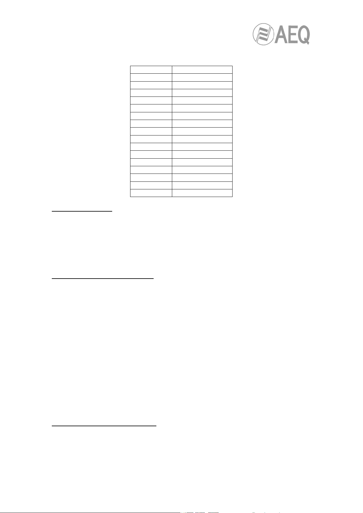
CHANNEL FREQUENCIES:
CHANNEL FREQUENCY
0 161.00000
1 161.00625
2 161.01250
3 161.01875
4 161.02500
5 161.03125
6 161.03750
7 161.04375
8 161.05000
9 161.05625
A 161.06250
B 161.06875
C 161.07500
D 161.08125
E 161.08750
F 161.09375
2.3 AUDIO INPUT
The audio input connector Is a XLR, 3 pin audio connector which allows the
connection of any kind of balanced or unbalanced audio signal source with
levels varying from MIC level to LINE level.
2.4 TX ANTENNA CONNECTOR
The TX Antenna connector Is a BNC connector used to connect the proper
antenna to the equipment.
The user can choose to connect the antenna to the equipment directly or to
connect an antenna with a cable.
The output impedance of this port is 50 ohms.
This port can be used as well to check the equipment specifications in a
laboratory bench.
2.5 LOW BATTERY INDICATOR
The low-battery indicator Is a red LED that shows the battery working status.
If the red led stays dark, then the battery is still in good working conditions.
AEQ LIVE 20 TR
.
8
Page 9

If the red led is lighting, then means that the approximate remaining work time is
around 20 minutes.
The decision to send the low battery message to the red light is taken by one of
the inner microcontrollers.
One ADC (Analog to Digital Converter) takes the battery voltage data and then
the microcontroller takes the decision to turn on or not the red led.
2.6 AUDIO LEVEL ADJUSTMENT
The audio GAIN selector is a multi-position switch that provides audio level
adjustments for a wide variety of audio sources.
Its associated set of precision resistors allows the user to select gain preset
ranging from MIC level sources to LINE level sources.
This feature is very useful so that the user doesn’t need any type of external
attenuator to accommodate any type of audio signal source to the equipment
audio signal envelope.
2.7 PEAK AUDIO INDICATOR
When the red led is flashing, then the user is achieving the peak modulation
deviation.
This indicator is very usefully to adjust the GAIN pot in order to have the best
signal to noise ratio (SNR).
2.8 POWER SUPPLY
The LIVE 20 TR is powered by an internal Lithium / Ion battery DR-202. Please
never
substitute this battery for any other or connect the equipment to any
external feeder.
AEQ LIVE 20 TR
.
9
Page 10
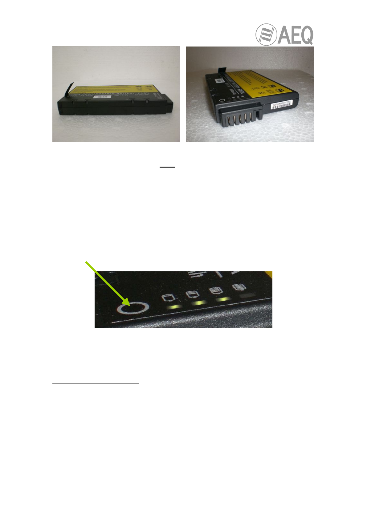
To re-charge a battery you must only use the charger supplied with the
equipment.
Before operating the equipment, please ensure that the battery is fully charged.
During normal (HI POWER) operation with fresh batteries you can expect more
than 4 hours of continuous operation.
It is also possible to check the charge of the battery by clicking the rounded
push button and the looking at the status of the 4 LEDs next to it.
2.9 OTHER CONNECTORS
In one side of the unit the user will find two connectors: one to charge the
internal Li-Ion battery, the other one to program the internal microcontrollers.
The first connector is a standard low power supply connector to give the user
the possibility to charge the battery from the external supplied charger.
AEQ LIVE 20 TR
.
10
Page 11
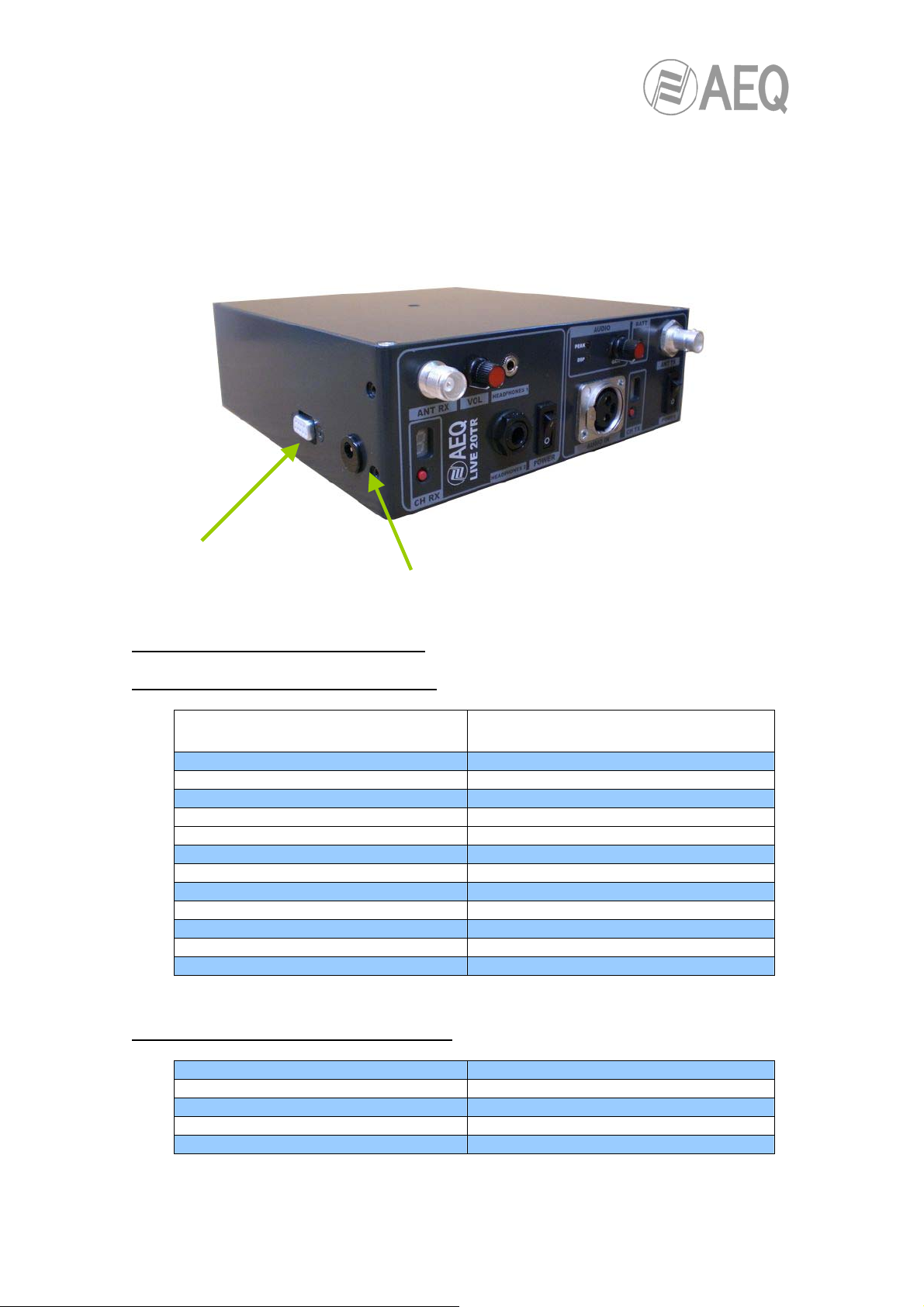
The second one is a standard SUB-D connector for programming and
reprogramming purposes, only to be used in factory.
Programming
SUB-D connector
3. TECHNICAL CHARACTERISTICS
3.1 TECHNICAL CHARACTERISTICS
VHF TRANSMITTER
Frecuency range 150-214 MHz
RF max. output power 3W over 50 Ohm
Number of channels 16 selectable. PLL, digital selector
Modulation type FM
Frequency stability Better than 2 ppm
Maximum deviation As required per the client
Spurious emissions < -60 dBm
Adjacent channel power -70 dB
Audio response As required per the client
Emphasis: As required per the client
Audio input Adjustable from MIC to LINE
Compressor-limiter
External charger
connector
3.2 MECHANICAL CHARACTERISTICS
TX antenna connector BNC Female
Audio input connector XLR-3 Female
Power DR-202 Li-Ion battery
Dimensions 190x74x182 mm
Weight 1.750 Kg ( batteries not included)
AEQ LIVE 20 TR
.
11
Page 12
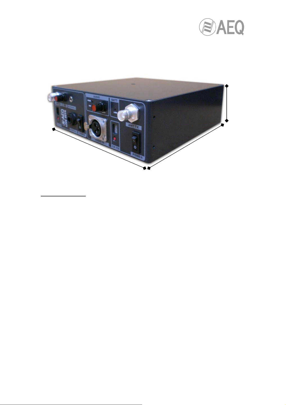
4. ACCESSORIES
190mm
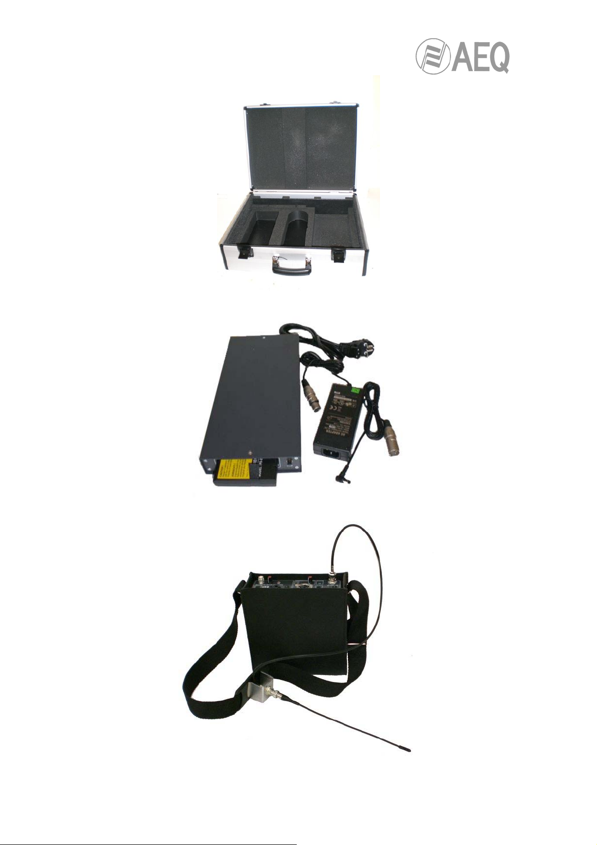
The equipment is delivered with the following accessories:
74mm
182mm
- LI-ION battery DR-202
- Flight case
- Shoulder antenna base
- CH-20 battery charger
- Antennas
- Carrying leather bag
AEQ LIVE 20 TR
.
12
Page 13
AEQ LIVE 20 TR
.
13
Page 14
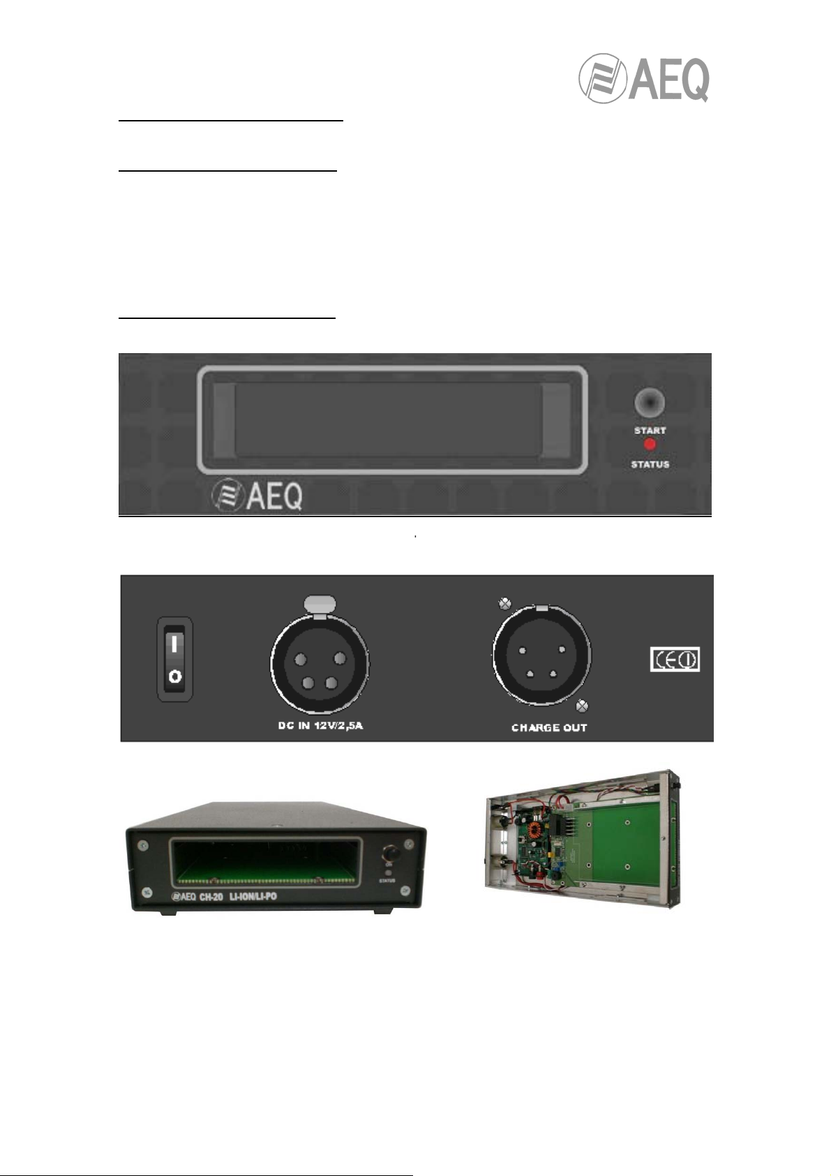
5. CH-20 BATTERY CHARGER
5.1 GENERAL DESCRIPTION
The CH-20 is a high-quality 12V fast charger, designed for charging Li-Ion and
Li-Po type DR-202 batteries.
5.2 FRONT AND REAR VIEW
AEQ LIVE 20 TR
.
14
Page 15

5.3 CONNECTION AND STARTING TO WORK
Connect the external power supply to the “DC IN” connector on the CH-20.
The CH-20 is internally protected with a automotive 7,5 A type fuse.
Insert the DR-202 battery into the CH-20 front hole or connect the LIVE 20 TR
to the back “CHARGE OUT” connector with the supplied cable.
Switch on the CH-20 with the back panel switch.
Start the charge process by pressing the “START” button.
The charger will start evaluating the battery, so if the charge is very low, the
charger will send several high-current impulses to try to fix it; if this is not
possible, then you will hear 4 beeper sounds.
In case of doubt, repeat the charge process. When it reaches a suitable tension
a beeper sounds and the LED remains fixed in green until it detects 3 elements
and it blinks 3 times.
The end of the charge process will be indicated by the LED in orange and beep
sound.
The finish of the charge process can be interrupted at any time by pressing the
“START” button.
IMPORTANT NOTE:
Never charge one battery inside CH-20 together with another battery inside the
LIVE 20 TR.
AEQ LIVE 20 TR
.
15
Page 16

5.4 INDICATIONS
LED “STATUS” flashes green at one-second intervals:
o The CH-20 is ready for use
LED “STATUS” glow green constantly after the “START” button is
pressed:
o The CH-20 is in the automatic detection process
(may take up 5 minutes)
LED “STATUS” flashes 3 times green to indicate the number of cells
inside the DR-202 (3 cells):
o The charge process start.
LED “STATUS” flashes orange and beeper sound:
o To indicate the DR-202 battery is approximately 95% fully
charged.
LED “STATUS” flashes orange to indicate 3 cells inside DR-202 and
beeper sounds:
o The charge process is completed
LED “STATUS” flashes red and beeper sounds:
o There are an error message with the following cases:
Battery broken
Input voltage too low
Reverse polarity at input
Circuit broken at charge output
Short circuit at charge output
Maximum charge time exceeded (3 hours)
Battery bad contact
IMPORTANT NOTE:
We recommend making two or three complete charge processes to assure an
optimal yield of the DR-202 battery.
The cable of the feeder to the cable of charge of the LIVE 20 TR NEVER must
be connected directly.
16
AEQ LIVE 20 TR
.
Page 17
5.5 CHARACTERISTICS
Input voltage: 11...15 VDC
Cell count: 1...4 Li-Ion/LiPo
Charge current: 2 A
Charge termination: Automatic
Dimensions: 300x14,5x41,5 mm
5.6 PROTECTIONS
Input reverse polarity
Output reverse polarity
Output short circuit
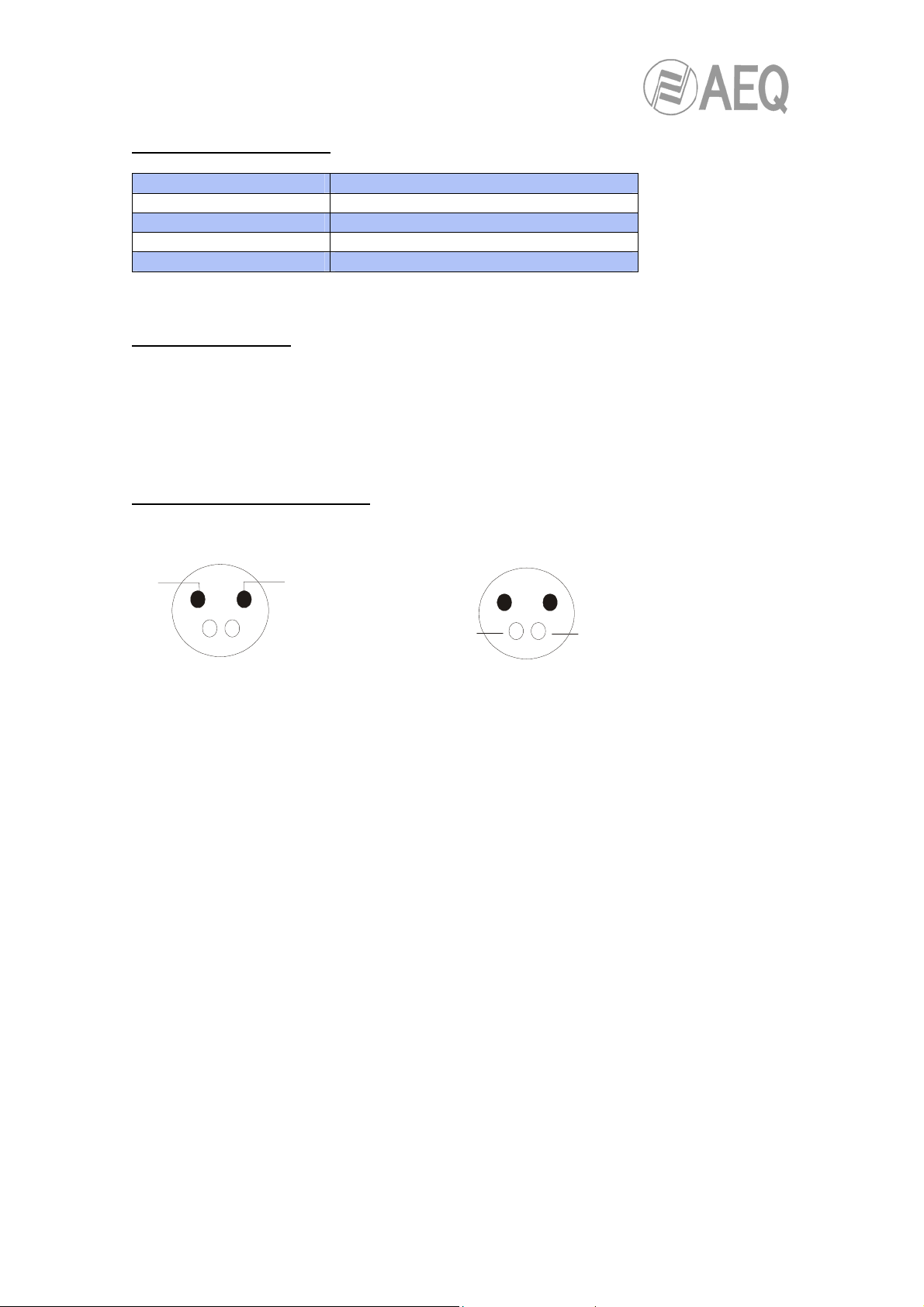
5.7 CONNECTORS PINOUTS
XLR4-HP XLR4-MP
GND DC IN
14
3
2
14
GND
2
3
CHARGE OUT
AEQ LIVE 20 TR
.
17
Page 18

ANNEX1. CONNECTORS PINOUT
Audio Input connector: XLR 3p Female
1. GND
2. Phase +
3. Phase -
TX Antenna connector: BNC Female
ANNEX 2. SECURITY RECOMMENDATIONS
Please do not switch on the equipment until you have connected the proper
antenna to the termination point labelled ANT TX.
AEQ LIVE 20 TR
.
18
Page 19

A.E.Q. Warranty
AEQ guarantees that this product has been designed and manufactured under
a certified Quality Assurance System and according to the ISO 9001/2002
Standard. AEQ therefore Guarantees that the necessary test protocols to
assure the proper operation and the specified technical characteristics of the
product have been followed and accomplished. This includes that the general
protocols for design and production and the particular ones for this product are
conveniently documented.
1. - The present guarantee does not exclude or limit in any means any legally
recognized right of the client.
2. - The period of guarantee is defined to be twelve natural months starting from
the date of purchase of the product by the first client. To be able to apply to the
established in this guarantee, it is compulsory condition to inform the authorized
distributor or –to its effect- an AEQ Sales office or the Technical Service of AEQ
within thirty days of the appearance of the defect and within the period
of guarantee, as well as to facilitate a copy of the purchase invoice and serial
number of the product.
It will be equally necessary the previous and expressed conformity from the
AEQ Technical Service for the shipment to AEQ of products for their repair or
substitution in application of the present guarantee. In consequence, return of
equipment that does not comply with these conditions will not be accepted.
3. -AEQ will at its own cost repair the faulty product once returned, including the
necessary labour to carry out such repair, whenever the failure is caused by
defects of the materials, design or workmanship. The repair will be carried out in
any of the AEQ authorized Technical Service Center.
This guarantee does not include the freight charges of the product to or from
such Authorized Technical Service Center.
4. – No Extension of the Guarantee Period for repaired product shall be applied.
Nor shall a Substituted Products in application of this Guarantee be subject to
Guarantee Period Extension.
5. - The present guarantee will not be applicable in the following situations:
Improper use or Contrary use of the product as per the User or Instruction
Manual; violent manipulation; exhibition to humidity or extreme thermal or
19
AEQ LIVE 20 TR
.
Page 20
environmental conditions or sudden changes of such conditions; electrical
discharges or lightning; oxidation; modifications or not authorized connections;
repairs or non-authorized disassembly of the product; spill of liquids or
chemical products.
6. - Under no circumstances, whether based upon this Limited Guarantee or
otherwise, shall AEQ, S.A. be liable for incidental, special, or consequential
damages derived from the use or from the impossibility of using the product.
AEQ shall not be liable for loss of information in the disks or data support that
have been altered or found to be inexact, neither for any accidental damage
caused by the user or other persons manipulating the product.
A.E.Q., S.A., the manufacturer of this equipment, is a
“Registered Company” by AENOR with reg. no: ER-080/1/96, in accordance
with UNE standard EN - ISO -9001
No part of this manual may be reproduced, transmitted or transcribed in any
form or by any means, without the prior written permission of AEQ S.A.
(APLICACIONES ELECTRÓNICAS QUASAR S.A.)
AEQ LIVE 20 TR
.
20
 Loading...