

Page 1
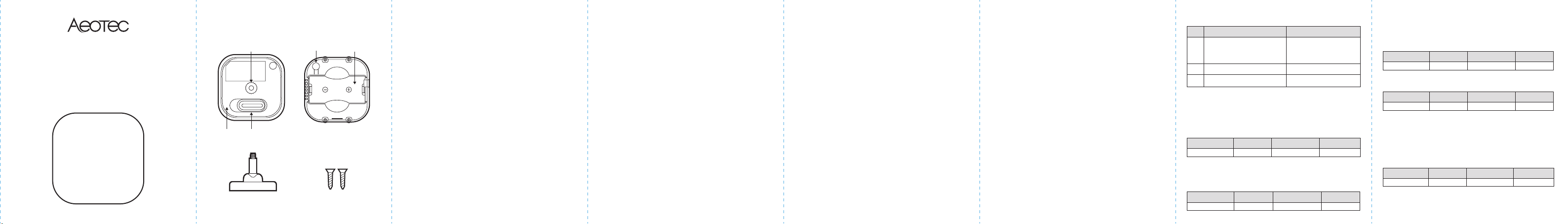
TriSensor
ZWA005
Used in this guide.
Threaded
hole
LockBackplate
Back-Mount
Arm
Action Button
Screw (x2)
CR123A
Battery slot
Important safety information.
Please read this and the electronic guide(s) at
http://support.aeotec.com/trisensor carefully. The failure to follow the
recommendations set forth by Aeotec Limited may be dangerous or
cause a violation of the law. The manufacturer, importer, distributor,
and / or reseller will not be held responsible for any loss or damage
resulting from not following any instructions in this guide or in other
materials.
TriSensor is intended for use in dry locations only. Do not use in
damp, moist, and / or wet locations.
Contains small parts; keep away from children.
Inclusion Description.
Press once TriSensor’s Action Button. If it is the first installation, the
yellow LED will keep solid until whole network processing is
complete. If successful, the LED will flash white -> green -> white ->
green, after 2 seconds finished. If failed, the yellow LED lasts for 30
seconds, then the green LED flashes once.
If it is the S2 encryption network, please enter the first 5 digits of
DSK.
Exclusion Description.
Press once TriSensor’s Action Button, the Purple LED will keep solid
until whole network processing is complete. If the exclusion is
successful, the LED will flash white -> green ->white -> green and
then LED will pulse a blue. If failed, the yellow LED lasts for 30
seconds, then the green LED flashes once.
Reset Description.
1. Power up the device.
2. Press and hold the button for 15s until Red Led is blinking,then
release the button.
Note: Please use this procedure only when the network primary
controller is missing or otherwise inoperable.
Wakeup Description.
Press and hold the button at least 2s until Red Led is on and then
release the button,device will send wakeup notification to controller if
device is in a Z-Wave network.
Quick start.
The following will step you through installing TriSensor and
connecting it to your Z-Wave network.
1. Select an installation location for TriSensor. The sensor uses light
and heat readings to detect motion, so avoid pointing it at
sources of either. Tips on optimising the installation location of
TriSensor can be found online in its digital guide.
2. Remove the backplate from TriSensor.
3. Remove the battery tab to engage the CR123A battery.
4. Replace the backplate.
5. Set your Z-Wave gateway into its ‘add device’ mode in order to
connect TriSensor to your Z-Wave system. Refer to the gateway’s
manual if you are unsure of how to perform this step.
6. Set TriSensor into its ‘add device’ mode;
a. If your Z-Wave gateway supports S2 encryption and DSK,
enter the first 5 digits of the DSK. Refer to ‘Used in this guide’
to locate the DSK if needed.
b. If your Z-Wave does not support DSK, press TriSensor’s
Action Button; its LED will turn yellow.
7. When TriSensor successfully joins your Z-Wave network, its LED will
turn alternate between white and green for 2 seconds. Should the
LED remain yellow and then flash green, TriSensor has been
unable to join your Z-Wave network; repeat the above steps and
please contact us for further support if needed.
8. TriSensor can be installed on a flat surface such as a shelf, in a
corner or on a wall using the Back-Mount Arm, or within a ceiling
or wall using its Recessor accessory (sold separately). If using
the Back-Mount Arm;
a. Screw Back-Mount Arm into the corresponding threaded hole
on the back of TriSensor.
b. Affix Back-Mount Arm to your desired location using the
provided double- sided tape or KA2.5×20 mm screws.
c. Angle TriSensor as desired.
Get help & learn more.
Should you encounter any problem with TriSensor, visit
http://support.aeotec.com/trisensor or contact our support team via
aeotec.com/contact. You can also learn more about TriSensor
features, configuration options, and technical specifications at the
link.
Gateway compatibility. To see if this device is known to be compatible with your
Z-Wave gateway, please refer to http://aeotec.com/z-wave-gateways
Declaration of Conformity. Aeotec Limited declares that TriSensor is in
compliance with the essential requirements and other relevant provisions of RED
2014/53/EU, RoHS 2011/65/EU, IEC62321:2008 and EN50581:2012. The full text
of the declaration is available
from https://support.aeotec.com/trisensor/doc
Specifications. ave devices operate between 868.40 & 926.3 MHz depending on
local restrictions. It uses up to -0.59dBm ERP of transmission power, enabling
wireless connectivity. Full information on device specifications and certifications at
support.aeotec.com/trisensor/specs
Association. The device supports 3 association groups,and each group supports
max 5 associated nodes.
Group 1 is lifeline group; all nodes which associated in this group will receive the
messages sent by device throughlifeline.
Group 2 is controlling group, all nodes associated in this group will be controlled
through BASIC_SET command by the device when device detects a movement
event. Basic Set Value is decided by Configuration Parameter 6.
Group 3 is controlling group, all nodes associated in this group will be controlled
through BASIC_SET command by the device when device detects an ambient
temperature alarm (Decided by Configuration Parameter 7).
The Command Class supported by each association group is shown in the
tablebelow:
Group
1
(Lifeline)
2
(Control)
3
(Control)
Command Class Configuration.
The device supports the controller to configure parameters of the device through
Configuration Command Class, and the device has 21 parameters available for
users to set according to their different needs:
1) Motion Retrigger Time
This parameter is configured the delay time before PIR sensor can be
triggered again to reset motion timeout counter. Value = 0 will disable PIR
sensor from triggering until motion timeout has finished.
Parameter Number
2) Motion Clear Time.
This parameter is configured the time to clear motion event after a motion event
detected. Time to motion clear, the device will send a clear event report to
controller and send BASIC_SET= 0x00 to nodes associated in group 2. Unit:
Second.
Parameter Number
CommandClass Command
COMMAND_CLASS_NOTIFICATION
COMMAND_CLASS_SENSOR_BINARY C
OMMAND_CLASS_SENSOR_MULTILEVEL
COMMAND_CLASS_BATTERY
COMMAND_CLASS_DEVICE_RESET_LOCALLY
COMMAND_CLASS_BASIC (HomeSecurity)
COMMAND_CLASS_BASIC(Temperature) BASIC_SET
Size (Byte) Available Settings Default value
1
2 2 2401 ~ 32767
2
Size (Byte) Available Settings Default value
NOTIFICATION_REPORT
SENSOR_BINARY_REPORT
SENSOR_MULTILEVEL_REPORT
BATTERY_REPORT
DEVICE_RESET_LOCALLY_NOTIFICATION
BASIC_SET
300 ~ 32767
3) Motion Sensitivity.
This parameter is configured the sensitivity that motion detect. 0 – PIR sensor
disabled.
1 – Lowest
sensitivity. 11 – Highest
11 – Highest sensitivity.
Parameter Number
3 1 110 ~ 11
4) Binary Sensor Report Enable.
‘0’ – Disable sensor binary report when motion event is detected or cleared.
‘1’ – Enable sensor binary report when motion event is detected or cleared.
Parameter Number
4 1 00 , 1
5) Disable BASIC_SET to Associated nodes.
This parameter is configured the enabled or disabled send BASIC_SET
command to nodes that associated in group 2 and group 3.
0 – Disabled All Group Basic Set Command
1 – Enabled Group 2 Basic Set Command, Group 3 Basic Set Command is
disabled.
2 – Enabled Group 3 Basic Set Command, Group 2 Basic Set Command is
disabled.
3 – Enabled Group 2 and Group 3 Basic Set Command.
Parameter Number
5 1 30 ~ 3
6) Basic Set Value Settings for Group 2.
‘0’ – Send BASIC_SET = 0xFF to devices associated in Group 2 when motion
event is triggered, send BASIC_SET = 0x00 to devices associated in
group 2 when motion event is cleared.
Size (Byte) Available Settings Default value
Size (Byte) Available Settings Default value
Size (Byte) Available Settings Default value
Page 2
‘1’ – Send BASIC_SET = 0x00 to devices associated in Group 2 when motion
event is triggered, send BASIC_SET = 0xFF to devices associated in
group 2 when motion event is cleared.
‘2’ – Send BASIC_SET = 0xFF to devices associated in Group 2 when motion
event is triggered.
‘3’ – Send BASIC_SET = 0x00 to devices associated in Group 2 when motion
event is triggered.
‘4’ – Send BASIC_SET = 0x00 to devices associated in Group 2 when motion
event is cleared. ‘5’ – Send BASIC_SET = 0xFF to devices associated in
Group 2 when motion event is cleared.
Parameter Number
6 1 00 ~ 5
7) Temperature Alarm Value.
This parameter is configured the threshold value that alarm level for
temperature. When the current ambient temperature value is larger than this
configuration value, device will send a BASIC_SET = 0xFF to nodes
associated in group 3. If current temperature value is less than this value,
device will send a BASIC_SET = 0x00 to nodes associated in group 3.
Value = [Value] × 0.1(Celsius / Fahrenheit)
Parameter Number7Size (Byte) Available Settings Default value
8) Led Indicate Disable.
This parameter is configured the Led light on disable or enable.
‘1’ – Enable Led Blink when device detects a motion event.
‘0’ – Disable Led Blink. This configuration is not affect inclusion, exclusion and reset.
Parameter Number
10 1 10 , 1
Size (Byte) Available Settings Default value
EU/AUUS2
-400 ~ 1185 (Fahrenheit) 750 (Fahrenheit)
2
Size (Byte) Available Settings Default value
239 (Celsius)-400 ~ 850 (Celsius)
9) Led Color For Motion Event Report.
‘0’ – Disable.
‘1’ – Red.
‘2’ – Green.
‘3’ – Blue.
‘4’ – Yellow.
‘5’ – Pink.
‘6’ – Cyan.
‘7’ – Purple.
‘8’ – Orange.
Parameter Number
11 1 20 ~ 8
10) Led Color For Temperature Sensor Report.
‘0’ – Disable.
‘1’ – Red.
‘2’ –Green.
‘3’ – Blue.
‘4’ – Yellow.
‘5’ – Pink.
‘6’ – Cyan.
‘7’ – Purple.
‘8’ – Orange.
Parameter Number
Size (Byte) Available Settings Default value
Size (Byte) Available Settings Default value
12 1 00 ~ 8
11) Led Color For Light Sensor Report.
‘0’ – Disable.
‘1’ – Red.
‘2’ –Green.
‘3’ – Blue.
‘4’ – Yellow.
‘5’ – Pink.
‘6’ – Cyan.
‘7’ – Purple.
‘8’ – Orange.
Parameter Number
Size (Byte) Available Settings Default value
13 1 00 ~ 8
12) Led Color For Battery Report.
‘0’ – Disable.
‘1’ – Red.
‘2’ –Green.
‘3’ – Blue.
‘4’ – Yellow.
‘5’ – Pink.
‘6’ – Cyan.
‘7’ – Purple.
‘8’ – Orange.
Parameter Number
Size (Byte) Available Settings Default value
14 1 00 ~ 8
13) Led Color For Wakeup Notification Report.
‘0’ – Disable.
‘1’ – Red.
‘2’ –Green.
‘3’ – Blue.
‘4’ – Yellow.
‘5’ – Pink.
‘6’ – Cyan.
‘7’ – Purple.
‘8’ – Orange.
Parameter Number
Size (Byte) Available Settings Default value
15 1 00 ~ 8
14) Temperature Scale Setting.
Configure temperature sensor scale type, Temperature to report in Celsius or
Fahrenheit.
0 – Celsius (C).
1 – Fahrenheit (F).
Parameter Number
20
15) Temperature Threshold Value to Report.
Change threshold value for change in temperature to induce an automatic
report for temperature sensor. Scale is identical setting in Parameter No.20.
Setting of value 20 can be a change of -2.0 or +2.0 (C or F depending on
Parameter No.20) to induce automatic report or setting a value of 2 will be a
change of 0.2(C or F).
Parameter Number
Size (Byte) Available Settings Default value
EU/AU
US 1
1
0 , 1
Size (Byte) Available Settings Default value
21 2 200 ~ 250
16) Light intensity Threshold Value to Report.
Chang
Size (Byte) Available Settings Default value
22 2 1000 ~ 10000
17) Temperature Sensor Report Interval.
This parameter is configured the time interval for temperature sensor report.
This value is larger, the battery life is longer. And the temperature value
changed is not obvious. Unit: Second.
Parameter Number
Size (Byte) Available Settings Default value
23 2 36001 ~ 32767
18) Light Sensor Report Interval.
This parameter is configured the time interval for light sensor report. This
value is larger, the battery life is longer. And the light intensity changed is not
obvious. Unit: Second.
Parameter Number
00 , 1
1
24 2 36001 ~ 32767
Temperature Offset Value.
The current measuring temperature value can be add and minus a value by this
setting. The scale can be decided by Parameter Number 20.
Temperature Offset Value = [Value] * 0.1(Celsius / Fahrenheit)
Parameter Number
Size (Byte) Available Settings Default value
Size (Byte) Available Settings Default value
30 2 0-200 ~ 200
19) Light Intensity Offset Value
The current measuring light intensity value can be add and minus a value by
this setting.
Parameter Number
Size (Byte) Available Settings Default value
31 2 0-1000 ~ 1000
20) Light Sensor Calibrated Coefficient.
This configuration defines the calibrated scale for ambient light intensity.
Because the method and position that the sensor mounted and the cover of
sensor will bring measurement error, user can get more real light intensity by
this parameter setting. User should run the steps as blows for calibrating.
1) Set this parameter value to default (Assumes the sensor has been added
in a Z- Wave Network).
2) Place a digital luxmeter close to sensor and keep the same direction,
monitor the light intensity value (Vm) which report to controller and record
it. The same time user should record the value (Vs) of luxmeter.
3) The scale calibration formula: k = Vm / Vs.
4) The value of k is then multiplied by 1024 and rounded to the nearest whole
number.
5) Set the value getting in 5) to this parameter, calibrate finished. For
example, Vm = 300, Vs = 2600, then k = 2600 / 300 = 8.6667 k = 8.6667 *
1024 = 8874.7 ≈ 8875
The parameter should be set to 8875.
Parameter Number
Size (Byte) Available Settings Default value
100 2 10241 ~ 32767
All Supports Command Class.
This device supports Z-Wave Command Class as follows:
COMMAND_CLASS_ZWAVEPLUS_INFO (V2)
COMMAND_CLASS_SECURITY (V1)
COMMAND_CLASS_SECURITY_2 (V1)
COMMAND_CLASS_TRANSPORT_SERVICE (V2)
COMMAND_CLASS_VERSION (V2)
COMMAND_CLASS_POWERLEVEL (V1)
COMMAND_CLASS_ASSOCIATION (V2)
COMMAND_CLASS_MULTI_CHANNEL_ASSOCIATION (V3)
COMMAND_CLASS_ASSOCIATION_GRP_INFO (V1)
COMMAND_CLASS_MANUFACTURER_SPECIFIC (V2)
COMMAND_CLASS_DEVICE_RESET_LOCALLY (V1)
COMMAND_CLASS_BATTERY (V1)
COMMAND_CLASS_WAKEUP (V2)
COMMAND_CLASS_NOTIFICATION (V8)
COMMAND_CLASS_SENSOR_BINARY (V2)
COMMAND_CLASS_SENSOR_MULTILEVEL (V7)
COMMAND_CLASS_CONFIGURATION (V1)
COMMAND_CLASS_SUPERVISION (V1)
FCC Notice. This device complies with part 15 of the FCC rules. Operation is
subject to the following two conditions: (1) this device may not cause harmful
interference, and (2) this device must accept any interference received, including
interference that may cause undesired operation.
The manufacturer is not responsible for any radio or TV interference caused by
unauthorized modifications to this equipment. Such modifications could void the
user’s authority to operate the equipment.
This equipment has been tested and found to comply with the limits for a Class B
digital device, pursuant to part 15 of the FCC Rules. These limits are designed to
provide reasonable protection against harmful interference in a residential
installation. This equipment generates uses and can radiate radio frequency
energy and, if not installed and used in accordance with the instructions, may
cause harmful interference to radio communications. However, there is no
guarantee that interference will not occur in a particular installation. If this
equipment does cause harmful interference to radio or television reception, which
can be determined by turning the equipment off and on, the user is encouraged to
try to correct the interference by one or more of the following measures:
- Reorient or relocate the receiving antenna.
- Increase the separation between the equipment and receiver.
- Connect the equipment into an outlet on a circuit different from that to which the
receiver is connected.
- Consult the dealer or an experienced radio/TV technician for help.
- This device and its antenna(s) must not be co-located or operating in
conjunction with any other antenna or transmitter.
FCC ID: 2AOGIZWA005
service@aeotec.com
www.aeotec.com
 Loading...