

Page 1
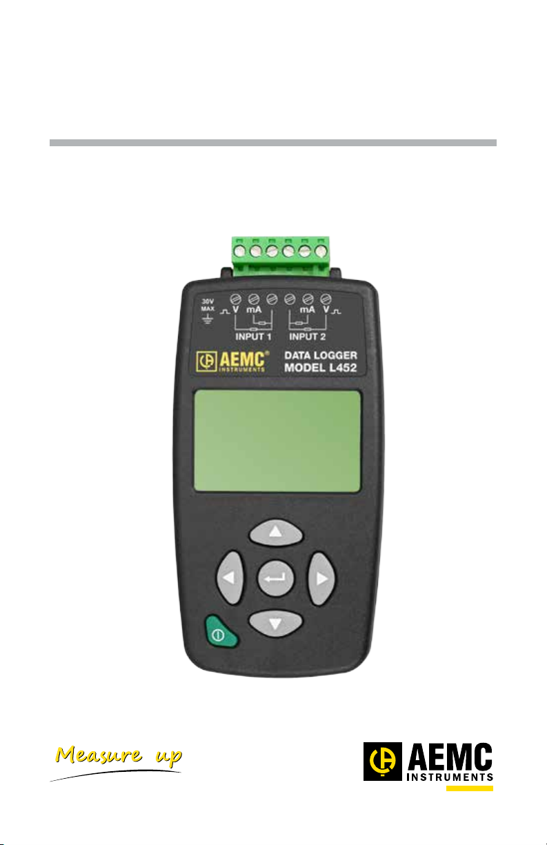
Data Logger
Model L452
Quick Start Guide
ENGLISH
www.aemc.com
®
CHAUVIN ARNOUX GROUP
Page 2

Statement of Compliance
Chauvin Arnoux®, Inc. d.b.a. AEMC® Instruments
certifies that this instrument has been calibrated
using standards and instruments traceable to
international standards.
We guarantee that at the time of shipping your
instrument has met its published specifications.
An NIST traceable certificate may be
requested at the time of purchase, or obtained
by returning the instrument to our repair and
calibration facility, for a nominal charge.
The recommended calibration interval for this
instrument is 12 months and begins on the date of
receipt by the customer. For recalibration, please
use our calibration services. Refer to our repair
and calibration section at www.aemc.com.
Serial #: ________________________________
Catalog #: 2153.51
Model #: L452
Please fill in the appropriate date as indicated:
Date Received: _________________________________
Date Calibration Due:
_______________________
Chauvin Arnoux®, Inc.
d.b.a AEMC® Instruments
www.aemc.com
Page 3
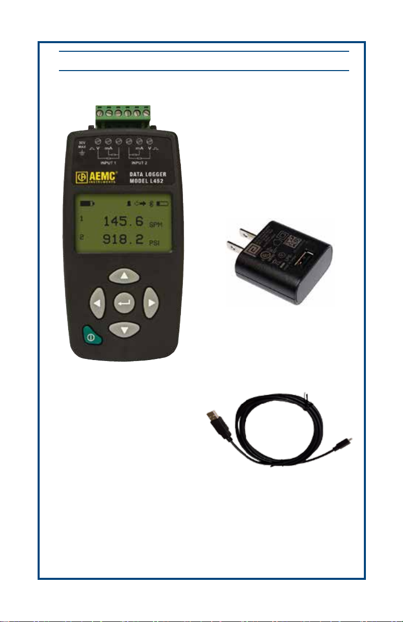
PRODUCT PACKAGING
US 120V Wall Plug to USB
Cat. #2153.78
Data Logger Model L452
Cat. #2153.51
Also Included:
(1) USB Stick with User Manual & DataView
Cable - 6 ft USB
Cat. #2138.66
®
Software
Page 4
Before using your Data Logger Model L452 for the rst time, please take a moment to
review the following.
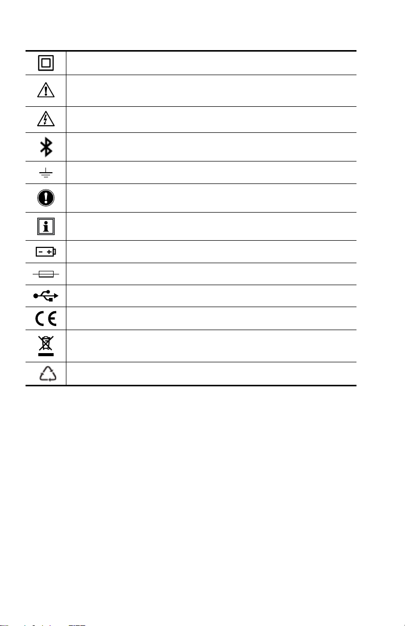
Signies that the instrument is protected by double or reinforced insulation.
CAUTION - Risk of Danger! Indicates a WARNING that the operator must
refer to the User Manual for instructions before operating the instrument
in all cases where this symbol is marked.
Risk of electric shock. The voltage at the parts marked with this symbol
may be dangerous.
Bluetooth enabled.
Ground/Earth.
Important instructions to read and understand completely.
Important information to acknowledge.
Battery.
Fuse.
USB socket.
Compliance with the Low Voltage & Electromagnetic Compatibility European directives (73/23/CEE & 89/336/CEE)
In the European Union, this product is subject to a separate collection
system for recycling electrical and electronic components In accordance
with directive WEEE 2002/96/EC.
The product has been declared recyclable.
Denition of Measurement Categories (CAT)
• CAT II Measurements taken on circuits directly connected to low-voltage installations.
Example: power supply to domestic electrical appliances and portable tools.
• CAT III Measurements taken on building installations.
Example: distribution panel, circuit-breakers, machines or xed industrial devices.
• CAT IV Measurements taken at the source of low-voltage installations.
Example: power feeders, counters and protection devices.
Page 5
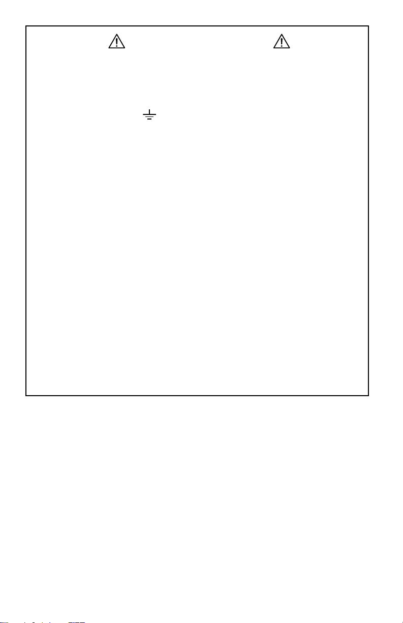
Precautions Before Use
These warnings are provided to ensure the safety of personnel. Please read and
comply with these precautions.
This instrument complies with safety standard EN 61010-1 (Ed 3) and IEC 61010.2030 (Ed 1) for voltages and categories of installation, at an altitude below 2000m (6562
ft) and indoors, with a degree of pollution at most equal to 2. The instrument operates
at 30V maximum to ground (
• Do not use this instrument in an explosive atmosphere or in the presence of
ammable gases.
• Observe the maximum voltages and intensities assigned between terminals
and ground/earth.
• Do not use the instrument if it appears damaged, incomplete, or improperly
closed.
• Before each use, check the condition of the insulation of cables, case, and
accessories. Anything which appears damaged (even partially) must be
reported for repair or scrapping.
• Use only leads and accessories that meet instrument specications.
• Observe the environmental specications for the use of this instrument, as
specied in § 7 of the User Manual.
• Do not modify the instrument. Use only original replacement parts. Repairs
or adjustments must be performed by authorized personnel.
• Replace the batteries when they can no longer hold a charge. Disconnect
all cables from the instrument before opening the access door to the batteries, as explained in § 8.1.3 of the User Manual.
• Use protective equipment as required by the environment in which you are
operating this instrument.
• When handling probes, probe tips, current sensors, signal conditioners, and
alligator clips, keep ngers behind the guard.
).
Page 6

Installing Batteries
The Model L452 can operate on two sources of power:
• USB cable connected to an external power source, such as a computer or wall plug
adapter.
• Two internal 1.2V AA 2400mAh NiMH rechargeable batteries
You must insert the batteries into the instrument before use, even if you plan to run the
instrument on USB power.
1. Holding the instrument rmly, slide the back cover to the right and remove it.
2. Insert the two batteries, ensuring the positive and negative ends are properly
aligned.
3. Replace the back cover by aligning the tabs in the cover with the corresponding
slots in the instrument body, and then sliding the cover to the left until it locks in
place.
NOTE: If the Model L452 is stored without the batteries installed, the internal clock will
need to be reset, as instructed in the following section.
Initial Setup
NOTE: It is recommended to fully charge the batteries before using the instrument (12hrs)
The instrument can be set up two ways:
• DataView Data Logger Control Panel
• Model L452 Front Panel Interface
Setup via the DataView® Data Logger Control Panel
Initial setup via the Control Panel requires three steps:
• Installing DataView
• Connecting the instrument to the computer via USB cable or Bluetooth
• Conguring the instrument’s settings in the Control Panel
Installing DataView® and the Data Logger Control Panel
DataView® installation may dier slightly, depending on your operating system. The follow-
ing instructions are based upon a Windows 7 operating system.
1. Ensure that the USB cable is not connected to the computer. Then insert the
USB thumb drive into an available USB port on your computer. If Autorun is
enabled, an AutoPlay window appears on your screen. Click “Open folder to view
les” to display the DataView
Windows Explorer to locate and open the USB drive labeled “DataView.”
2. When the DataView
run the installation program.
3. At the Setup screen, choose the desired language and installation options, then
click Install.
4. At the InstallShield Wizard welcome screen, click Next.
5. Read the license agreement and indicate your acceptance by clicking “I accept
the terms of the license agreement.” Then click Next.
®
and the Data Logger Control Panel on your computer
®
folder. If Autorun is not enabled or allowed, use
®
folder is open, nd the le Setup.exe and double-click it to
Page 7

6. At the Customer Information screen, enter your username and company name.
Also choose whether this installation is for all users of the computer, or just for
your username. Click Next to proceed.
®
7. The next screen lets you select the DataView
you are prompted to select individual components to install. To install the full
DataView
8. You are now prompted to select the Control Panel(s) you want to install. Unless
you have other types of AEMC
®
product, select Complete and then click Next.
®
instruments, we recommend that you select Data
setup. If you choose Custom,
Logger and deselect the rest. You should also check the option PDF-XChange,
which is a requirement if you plan to create .pdf versions of DataView reports.
After you nish selecting and deselecting Control Panels, click Next.
9. Click Install to begin installation.
®
10. The InstallShield Wizard now installs DataView
bar displays the progress of the installation. During installation, you may see
a warning message about installing DataView
. During this process, a status
®
with your AEMC® instrument
connected to the computer. If the instrument or USB cable is connected,
disconnect it now. Then click OK to proceed.
11. After a few moments, a screen appears informing you that installation is
complete. Click Finish to leave the InstallShield Wizard. You are now asked
whether or not you would like to view instructions about how to connect the
®
instrument or cable to the USB port on the computer. Click Yes to view
AEMC
these instructions, or No to proceed.
®
12. Close the DataView
Setup screen. The DataView folder now appears on your
computer desktop. This folder contains the DataView and Data Logger Control Panel icons, along with the icon(s) for any other Control Panel(s) you have
installed.
Connecting via USB Cable
The following steps assume the instrument has not been previously connected to the computer via USB cable:
1. Plug one end of the cable into the instrument, and the other end into an available
USB port on the computer. Then press the
button until the message POWER
ON appears on the LCD. Wait for driver installation to nish before proceeding to
the next step (a message appears on your computer when driver installation is
complete).
2. Open the Data Logger Control Panel.
3. In the menu bar at the top of the screen, select Help. In the drop-down menu that
appears, click the option Help Topics. This opens the Data Logger Control Panel
Help system.
4. Use the Contents window in the Help system to locate and open the topic
“Connecting to an Instrument,” which describes how to connect the Model L452
to the computer.
When the instrument is connected, its name appears under the Data Logger Network in the
Control Panel’s navigation frame.
Page 8

Connecting via Bluetooth
Bluetooth must be enabled and congured on the instrument before you can connect to the
computer:
1. At the “home” (Channel 1 & 2 Measurement Data) screen press ► four times to
display the Language and Date/Time Format screen displayed. Then press ▼
four times to display the Bluetooth Enabled/Visibility screen.
2. To change the Bluetooth setting, press
toggle through the options Enabled and Disabled. When the desired option is displayed, press to save the selection and leave edit mode. When the Enabled
option is selected, the Bluetooth icon appears in the icon bar.
3. To change the Visibility setting, press
▼ to select the Visibility eld. Press to initiate edit mode, then use ▲ or ▼
to toggle through the two options Visible and Invisible. (To connect the instrument for the rst time, this should be set to Visible.) When the desired option is
selected, press
4. To change the instrument’s Bluetooth name, press ▼ at the Bluetooth Enabled/
Visibility screen. This displays the Bluetooth Name screen.
5. To change the editable part of the name, press
change the selected character. Then press ► to highlight the next character
and use the ▲ and ▼ buttons to make your change. You can also press ◄ to
navigate back to a previous character. When nished, press to save your
changes.
With Bluetooth enabled and congured on the instrument, you can connect to the computer.
These steps assume the instrument has not been previously connected via Bluetooth:
1. Open the Bluetooth Devices dialog on your computer to pair the Model L452 with
your computer. Dierent operating systems have dierent steps for opening this
dialog, so consult your computer’s documentation for instructions.
2. Once the dialog is displayed, click Add a Device. A dialog box appears listing the
locally available Bluetooth devices.
3. Find the instrument, which will appear listed by its Bluetooth name as displayed
in the Model L452’s Bluetooth Name screen. If the name does not appear, check
the Bluetooth Enabled/Visibility screen on the Model L452 to ensure the Visibility
eld is set to Visible. Also ensure the instrument is turned ON. If the name is visible, click it.
4. Enter the pairing code (0000) and click Next. A screen appears informing you that
the instrument has been successfully connected with the computer. Click Close
to exit the screen.
5. Open the Data Logger Control Panel. In the menu bar at the top of the screen,
select Help. In the drop-down menu that appears, click the option Help Topics.
This opens the Data Logger Control Panel Help system.
6. Use the Contents window in the Help system to locate and open the topic
“Connecting to an Instrument.”, which will explain how to connect the Model L452
to the computer.
to save the setting and leave edit mode.
twice, then use the ▲ or ▼ button to
to initiate selection mode. Then press
twice and use ▲ and ▼ to
When the instrument is connected, its name appears under Data Logger Network in the
Control Panel’s navigation frame.
Page 9

Conguring the Instrument via the Control Panel
1. With the instrument connected, click its name under Data Logger Network in the
Control Panel.
2. Select Instrument in the menu bar, and click Congure.
3. In the General tab of the Congure Instrument dialog box, set the instrument’s
clock, date/time format, and user interface language. Press the Help button at the
bottom of the dialog box for instructions.
Setup via the Model L452 User Interface
In addition to enabling/disabling and conguring Bluetooth, the following conguration
parameters can be set through the instrument’s front panel interface:
• Language
• Date and time
The “home” screen for the interface is the Channel 1 & 2 Measurement screen. You can
return to this screen at any time by giving the
press.
Choosing the Interface Language
1. At the “home” screen, press ► four times to display the Language and Date/Time
Format screen.
2. Press the Enter
3. Use the ▲ or ▼ button to cycle through the available languages. Choices are
English, Español, Italiano, Deutsch, and Français.
4. When the desired language choice is displayed, press
screens now appears in the selected language.
button twice.
button a short (less than 2 seconds)
. The text on all
Setting the Instrument Date and Time
1. With the Language and Date/Time Format screen displayed, press . This initi-
ates selection mode; the setting under the Language eld will change to blinking
reversed text.
2. Press ▼. The setting under Date/Time appears in blinking reversed text.
3. Press
4. Press ▲ or ▼ to cycle through the available options for date and time format.
5. After you make your selection, press
and Date/Time Format screen should now appear in regular text.
6. Press ▼ three times. The Date and Time screen now appears.
7. Press
blink. To change this number, press
▼ buttons to increase/decrease this number until the correct value is displayed.
To change the other two settings in the Date eld, press ► to navigate to the
number you want to set. Then press ▲ or ▼ to change the setting. You can also
use ◄ to navigate back to a previous number.
To change the Time eld, press ► while the last number in the Date eld is
selected. This highlights the rst number in the Time eld.
to initiate edit mode.
to save it. All elds on the Language
once to initiate selection mode. The rst number in the Date eld will
to initiate edit mode. Then use the ▲ and
Page 10

Alternatively, if you are not in edit mode (for example, you have opened the
Date and Time screen and only want to change the time while leaving the date
unchanged), press
the Date eld is blinking, press ▼. The rst number in the Time eld will blink;
press
8. Change the numbers in the Time eld, using the buttons as explained in the
steps above.
9. When you have nished setting the Date and Time values, press
changes and leave edit mode.
to initiate edit mode.
to initiate selection mode. Then while the rst number in
to save your
Channel Configuration
Channels can be congured either through the Data Logger Control Panel or the instrument
interface:
• Consult the Data Logger Control Panel Help system for information about conguration
through the Control Panel.
• Consult “L452 User Interface Screens” later in this Quick Start Guide for a table listing
all conguration screens available through the user interface. For detailed instructions
about how to complete these screens, see the Model L452 User Manual.
When conguring through the instrument’s interface, each of the instrument’s two channels
has its own set of conguration screens; the screens for one channel are essentially identical to the screens for the other. These screens allow you to:
• Enable and disable the channel. When disabled, measurements are neither recorded
nor displayed for the channel.
• Select the type of input. This can be analog (voltage or current), pulse, or event. Note
that both channels must have the same input type.
• Dene measurement units. These units are used when displaying measurement data.
• Dene scaling. This establishes the relationship between input and measurement units.
• Enable and dene alarm triggers. This determines whether or not (and under what
circumstances) the instrument reports an alarm condition.
Channels must be congured before you start a recording session.
Page 11

Recording Data
Recording sessions can be congured and scheduled via the Data Logger Control Panel,
as explained in the Help. The instrument’s user interface also includes a set of screens for
controlling and conguring a recording session. These screens enable you to:
• Specify the sample and storage periods to be used during the recording session
• Start a recording session immediately
• Schedule a recording for a future time
• Set a length of time for the recording to run
• Schedule start/stop dates and times for the recording
• Stop an in-progress recording
• Cancel a scheduled recording
The starting point for working with recordings is the Recording and Duration Screen. This
is the top-level screen for all recording-related activities. To see this screen, display the
“home” (Channel 1 & 2 Measurement Data) screen and press ►.
Consult the Model L452 User Manual for detailed information about conguring recording
sessions.
Starting a Recording Session
You can start a congured recording session immediately, or schedule one for a later date
and time. To start a recording immediately:
1. At the “home” screen press ► to display the Recording and Duration screen.
Note the Duration eld on this screen. This species how long the recording session will run. By default (assuming no session has been already scheduled), this
is 15 minutes. The Duration setting cannot be shorter than the Storage Period
setting.
2. To change the duration setting, press
to select the Duration eld. Then press to start edit mode, and use the buttons to enter a duration period
For example, to change the duration from 15 minutes to 3 days, select the “1” in
“15 min” and press
press ► to highlight the number “5.” Press ▼ twice to change this to “3.” Finally,
press ► to select the units, and use the ▲ and ▼ buttons to cycle through avail-
able choices. These include s (seconds), min, hours, days, and weeks. Select
“days” and press to save your change. (Alternately, instead of the Duration
eld you can use the Stop Date and Stop Time screen to determine how long the
recording session will run.)
3. To start the recording, press
immediately, using the conguration settings you have specied. The recording
session will end when the time interval dened by the Duration eld comes to an
end.
to begin edit mode. Use ▼ to change this to a zero, then
three times. The recording session starts
to initiate selection mode, and press ▼
Page 12

When a recording is active, the Recording icon appears in the icon bar at the top of the
screen. This icon appears as a solid circle. If you attempt to turn OFF the instrument by
pressing while a recording is in progress, the message RECORDING ACTIVE appears
on the screen. The button is otherwise disabled while a recording is in progress.
Scheduling a Recording Session
Instead of starting a recording immediately, you can schedule a recording for a future date
and time. Note that you can only schedule one recording at a time; to schedule a new
recording (1) the active recording must run to completion, or (2) you must cancel the earlier
recording.
1. At the “home” screen press ► to display the Recording and Duration screen.
2. Press ▼ twice to display the Start Date/Time screen.
3. Press
▲ and ▼ buttons to increase or decrease the number, and the ► and ◄ but-
tons to move from one eld to the next. Note that when you press ► when the
last number in the Start Date eld is selected, the selection will move to the rst
number in the Start Time eld. This enables you to edit both the date and time
in a single editing session. When you have nished entering the start date and
time, press to save your changes.
4. You now have two options for dening when the recording session ends. One is
by setting the Duration eld in the Recording and Duration screen. The other is
through the Stop Date/Time screen.
To set the Duration eld, press ▲ twice to return to the Recording and Duration
screen. Then complete the Duration eld.
To set the time and date for when the recording stops, press ▼ at the Start Date/
Time screen. This displays the Stop Date/Time screen.
5. By default, the settings on this screen reect the Duration setting. For example, if
the Duration eld is set to 24 hours, the stop date and time will be set to 24 hours
after the start date and time. To change this, press
tons to select and change settings, similar to setting the start date and time elds
as described in step 3 above.
6. When you have nished entering the stop date and time, press
changes. The Duration eld in the Recording and Duration screen will be updated
to reect the duration dened by your start date/time and stop date/time.
7. If it is not already displayed, navigate to the Recording and Duration screen.
Press
When Schedule appears, press to select it.
twice. The rst number under Start Date will be highlighted. Use the
twice. Then use the but-
to save your
twice. Then use the ▲ and ▼ buttons to toggle through the options.
When a recording is scheduled, the Recording icon
of the screen. This icon appears an empty circle. You can turn OFF the Model L452 with a
scheduled recording pending. When the start date and time occurs, the instrument will turn
itself back ON for the duration of the recording, after which it will automatically turn OFF.
appears in the icon bar at the top
Page 13

Stopping or Cancelling a Recording Session
As noted previously, you cannot start or schedule a recording session if (1) a recording is
active, or (2) another scheduled recording is pending. In either case, you will need to stop
or cancel the recording before you can start or schedule another.
To stop an active recording or cancel a scheduled one, display the Recording and Duration
screen.
• If a recording is active, the only option available on this screen will be Stop.
• If a recording is scheduled, the only option available on this screen will be Cancel.
In either case, press the
or canceled, depending on the selection. The Recording icon disappears, indicating no
recording is currently active or scheduled. In addition, the remaining recording-related
screens will become active, enabling you to start or schedule a new recording.
button three times. The recording will be immediately stopped
L452 User Interface Screens
The primary interface for working with the Model L452 consists of conguration and display
screens. These screens appear in the instrument’s front-panel LCD. The instrument’s buttons enable you to navigate these screens, select options, and enter information.
Screens are grouped into six categories:
• Measurement Data screens display data currently being measured on Channel 1 and/
or Channel 2.
• Recording screens congure, start, schedule, stop, and cancel a recording session.
• Channel 1 Conguration screens enables/disables Channel 1 and determines what
data is recorded by the channel and how it is displayed.
• Channel 2 Conguration screens are identical to Channel 1 Conguration screens,
except they apply to the instrument’s Channel 2.
• Instrument Conguration screens congure general instrument settings.
• Instrument Information screens display read-only settings on the instrument.
Each category has a “top level” screen; this is the rst screen that appears when you move
to the category. The following table is a graphical representation for how these categories
and screens are organized.
Page 14

Measurement
Data
Channels
1 & 2
Measurement
Data
(“Home”
screen)
Channel 1
Measurement
and Min/Max
Data
Channel 2
Measurement
and Min/Max
Data
*Not displayed when input is set to Event.
**Not displayed when input is set to Event or Pulse.
Recording Channel 1
Start/Stop/
Schedule/
Cancel a
Recording,
and Set
Duration
Sample
Period and
Storage
Period
Start Date
and Time
Stop Date
and Time
Conguration
Enabled/
Disabled and
Input Type
*Units *Units Memory Erase
**Low Scaling **Low Scaling Conguration
**High Scaling **High Scaling Date and Time Recording
**Alarm
Trigger
**Upper Limit
and Lower
Limit
Equivalence
(Pulse Input
Only)
Trigger (Event
Input Only)
Channel 2
Conguration
Enabled/
Disabled and
Input Type
**Alarm Trigger Bluetooth
**Upper Limit
and Lower
Limit
Equivalence
(Pulse Input
Only)
Trigger (Event
Input Only)
Instrument
Conguration
Language and
Date/Time
Format
and Min/Max
Reset
Reset
Enable/Disable
and Visibility
Bluetooth
Name
Instrument
Information
Model
Number,
Serial
Number, and
Firmware
Revision
Instrument
Name and
Location
Recording
Sessions
Name
Pressing the ► or ◄ button while in navigation mode moves from one category of screens
to the next. These buttons work from any screen in a category. For example, pressing ►
from any of the three Measurement Data screens displays the top-level Recording screen.
The categories are “cyclical,” pressing ► at an Instrument Information screen moves to the
top-level screen in Measurement Data, while pressing ◄ in a Measurement Data screen
displays the top-level Instrument Information screen.
The ▲ and ▼ buttons let you navigate the screens within each category. These are also
cyclical; pressing ▲ in a category’s top-level screen displays the bottom level screen in
that category, while pressing ▼ at the bottom-level screen displays the category’s top-level
screen.
Page 15

Repair and Calibration
To ensure that your instrument meets factory specications, we recommend that it be
scheduled back to our factory Service Center at one-year intervals for recalibration, or
as required by other standards or internal procedures.
For instrument repair and calibration:
You must contact our Service Center for a Customer Service Authorization Number
(CSA#). This will ensure that when your instrument arrives, it will be tracked and processed promptly. Please write the CSA# on the outside of the shipping container. If
the instrument is returned for calibration, please specify whether you want a standard
calibration, or a calibration traceable to N.I.S.T. (includes calibration certicate plus re-
corded calibration data).
Ship To: Chauvin Arnoux®, Inc. d.b.a. AEMC® Instruments
15 Faraday Drive
Dover, NH 03820 USA
Phone: (800) 945-2362 (Ext. 360)
(603) 749-6434 (Ext. 360)
Fax: (603) 742-2346 or (603) 749-6309
E-mail: repair@aemc.com
(Or contact your authorized distributor.)
Costs for repair, standard calibration, and calibration traceable to N.I.S.T. are available.
NOTE: You must obtain a CSA# before returning any instrument.
Technical and Sales Assistance
If you are experiencing any technical problems, or require any assistance with the proper operation or application of your instrument, please call, mail, fax or e-mail our technical support team:
Chauvin Arnoux®, Inc. d.b.a. AEMC® Instruments
200 Foxborough Boulevard
Foxborough, MA 02035 USA
Phone: (800) 343-1391
(508) 698-2115
Fax: (508) 698-2118
E-mail: techsupport@aemc.com
www.aemc.com
NOTE: Do not ship instruments to our Foxborough, MA address.
Page 16

06/17
99-MAN 100423 v4
Chauvin Arnoux
®
, Inc. d.b.a. AEMC® Instruments
15 Faraday Drive • Dover, NH 03820 USA • Phone: (603) 749-6434 • Fax: (603) 742-2346
www.aemc.com
 Loading...