

Page 1
AC Current Probe
Model JM850A
User Manual
DESCRIPTION
The JM850A (Catalog # 2110.87) is designed for use in industrial environments. The “sq uared” jaws
permit multiple conductor or bus bar positioning. The current output makes it the perfect tool for
measurement with DMMs, rec orders, power and harmoni c meters. Three ranges allo w you to obtain the
best resolution even on low current measurement. The Model JM850A is compatible with any AC
ammeter, multime ter, or other c urren t measu ring i nstrum ent with an in put im peda nce lower than 2.5Ω. To
achieve the stated accuracy, use the JM850A with an Ammeter having an accuracy of 0.75% or better.
WARNING
These safety warnings are prov ided to ensure the saf ety of personnel an d proper operatio n of the
instrument.
• Read the i nstruction ma nual completel y and follow all t he safety info rmation before attempting
to use or service this instrument.
• Use caution on any circuit: Potentiall y h igh vol t age s and currents may be prese nt and ma y pose
a shock hazard.
• Read the Safety Specifications section prior to using the current probe. Never exceed the
maximum voltage ratings given.
• Safety is the responsibility of the operator.
• ALWA YS connect the curre nt probe to the display device be fore clamping t he probe onto t he
sample being tested.
• ALWA YS inspect the instrumen t, p ro be , pr obe ca bl e, an d ou tp ut te rm inal s pri or to use. Replace
any defective parts immediately.
• NEVER use the current probe on electrical conductors rated above 600 V in overvoltage
category III (CAT III). Use extreme caution when clamping around bare conductors or bus bars.
INTERNATIONAL ELECTRICAL SYMBOLS
This symbol signifies that the cur rent prob e is protect ed by doubl e or reinfo rced ins ulation. Us e
only factory specified replacement parts when servicing the instrument.
This symbol signifies CAUTION! and requests that the user refer to the user manual before
using the instrument.
This is a type A current sensor. This symbol signifies that application around and removal
from HAZARDOUS LIVE conductors is permitted.
DEFINITION OF MEASUREMENT CATEGORIES
Cat. II: For m easurements performed on circuits directly co nnected to the electric al distribution system.
Examples are measurements on household appliances or portable tools.
Cat. III: For measurements performed in the building installation at the distribution level such as on
hardwired equipment in fixed installation and circuit breakers.
Cat. IV: For measurements performed at the primary electrical supply (<1000V) such as on primary
overcurrent protection devices, ripple control units, or meters.
RECEIVING YOUR SHIPMENT
Upon receiving your shipment, make sure that the contents are consistent with the packing list. Notify your
distributor of any missing items. If the equipment appears to be damaged, file a claim imm edi a tel y with t he
carrier and notify your distributor at once, giving a detailed description of any damage.
Page 2
Primary current
50A
200A
1000A
Accuracy %
3%
1.5%
1%
Phase shift
3°
1.5°
1°
Primary current
100A
400A
2000A
Accuracy %
1.5%
0.75%
0.5%
Phase shift
1.5°
0.75°
0.5°
Primary current
150A
600A
3000A
Accuracy %
1.5%
0.75%
0.5%
Phase shift
1.5°
0.75°
0.5°
ELECTRICAL SPECIFICATIONS
Current Range:
1 to 1000A AC continuous cycle
1 to 2000A AC continuous cycle
1 to 2400A AC continuous cycle for the
full temperature range
(3000A if temperature is < 35°C or 95°F)
Transformation Ratio:
1000:1, 2000:1, 3000:1
Output Signal:
1 mA AC/A AC (1A at 1000A)
0.5 mA AC/A AC (1A at 2000A)
0.333 mA AC/A AC (1A at 3000A)
Accuracy and Phase Shift*:
1000A RANGE
Load Impedance: 2 .5Ω
Overload: 1400A for 10 mn
Ampere Second Product: 25 A.s
Accuracy: Per IEC 185-26-27
Class 1 (2.5 VA) from 48 to 1000 Hz
99-MAN 100104.v7 03/17
Page 3

2000A RANGE
Primary current
100A
400A
2000A
Accuracy %
1.5%
0.75%
0.5%
Phase shift
1.5°
0.75°
0.5°
Primary current
150A
600A
3000A
Accuracy %
1.5%
0.75%
0.5%
Phase shift
1.5°
0.75°
0.5°
Load Impedance: 5Ω
Overload: 2400A for 10mn
Ampere Second Product: 60 A.s
Accuracy: Per IEC 185-26-27
Class 0.5 (5 VA) from 48 to 1000 Hz
3000A RANGE
Load Impedance: 10Ω
Overload: 3400A for 10mn
Ampere Second Product: 90 A.s
Accuracy: Per IEC 185-26-27
Class 0.5 (10 VA) from 48 to 1000 Hz
(*Reference conditions: 23°C±3°K, 20 to 85%
RH, 45 to 65 Hz, external magnetic field < 40
A/m, no DC component, no external current
carrying conductor, test sample centered.)
Frequency Range : 30 to 1000Hz; current
derating above 1000H z for cont in uo us use
Load Impedance: ≤ 10Ω
Working Voltage: 600V AC
Common Mode Voltage: 600V AC
Open Secondary Voltage:
42V max. by limiting circuit
Influence of Ad jac ent Conductor:
0.005A/A AC
Influence of Conductor in Jaw Opening:
1.5% ± 0.2A on 1000:1 range
1% ± 0.2A on 2000:1 range
1% ± 0.2A on 3000:1 range
MECHANICAL SPECIFICATIONS
Operating Temp.: 14° to 122°F (-10° to 50°C)
Storage Temp.: -13° to 176°F (-25° to 80°C)
Influence of Temperature: < 0.1% per 10°K
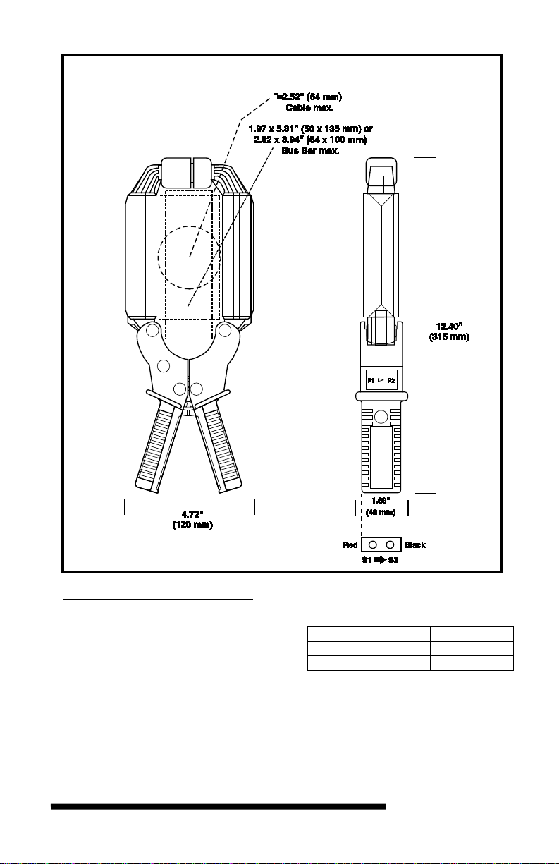
Jaw Opening: 3.54" (90 mm)
Maximum Conductor Size:
Cable: 2.52" ∅ max. (64mm)
Bus bar: 1.97 x 5.31" (50 x 135 mm)
2.52 x 3.94" (64 x 100 mm)
Envelope Protection: IP 20 (IEC 529)
Drop Test: 1 m (IEC 68-2-32)
Mechanical Shock: 100 g (IEC 68-2-27)
Vibration: 10/55/10Hz, 0.15 mm (IEC 68-2-6)
Polycarbonate Material:
Handles: 10% fiberglass charged
polycarbonate UL 94 V0
Jaws: ABS UL 94 V2
Dimensions:
4.72 x 12.40 x 1.9" (120 x 315 x 48 mm)
Weight: 2.65 lbs. (1200 g)
Colors: Dark gray handles with red jaws
Output:
Two standard safety banana jacks (4mm)
SAFETY SPECIFICATIONS
Electrical:
Double insulation or reinforced insulation between
primary or secondary and outer case of handle
upon IEC 1010-2-32
Common Mode Voltage:
600V Category III, Pollution: 2
ORDERING INFORMATION
Current Probe JM850A.................... Cat #2110.87
Accessories:
Lead, set of 2, 5ft Safety Leads
(1000V CAT IV) .................................. Cat#2152.24
Adapter BNC (Male) –Bannana (Female) (XM-BB)
(600V CAT III)..................................... Cat#2118.46
Page 4

OPERATION
Please make sure that you have already read and fully understand the WARNING section on page 1.
Making Measurements with the AC Current Probe Model JM850A
• Connect the black and red terminals to the Ampere AC range of your DMM or current measuring
instrument. Selec t the app ropriate c urrent range. If the curren t magni tude is u nkno wn, select th e high est
range (3000A AC / 1A AC) on t he switch pro be located insi de the handle. Clam p the probe around the
conductor to be tested, with the arro w pointed toward the load. If the re ading is less than 200mA or
20mA, select the lower ra nge until you obtain the best r esolution. Read the value display on the DMM
and multiply it by the range selected. (If readi ng = 0.259A on the 1000/1 range, the current flowing
through the probe is 0.259A x 1000 = 259A AC).
• For best accurac y: care full y center the c ondu ctor ins ide t he pr obe ja w, avoi d if possi ble, t he pro ximit y of
other conductors which may create noise.
Tips for Making Precise Measurements
• When using a current p robe with a meter, it is important to sel ect the range that provides the best
resolution. Failure to do this may result in measurement errors.
• Make sure that probe j aw mating sur faces are free of dus t and contaminati on. Contami nants cause air
gaps between t he ja ws, inc reas ing t he phase shift bet ween prim ary a nd sec o ndar y. It i s ver y criti cal for
power measurement.
MAINTENANCE:
Warning
• For maintenance use only original replacement parts.
• To avoid electrical shock, do not attempt to perform any servicing unless you are qualified to do so.
• To avoid elec trical shock a nd/or dam age to the i nst rume nt, do not get wate r or ot he r for eign a gents int o
the probe.
Cleaning
To ensure optimum p erforma nce, it is i mportant t o keep t he probe ja w mating surfaces cl ean at all tim es.
Failure to do so ma y res ult in error in readi ngs . The f ollowi ng is the r ecomm ende d proc edur e for cl eani ng
the probe jaws: Use a very fine sa nd p ape r ( f in e 6 00 ) to avoid scratchi n g th e j aw, then gently cle an with a
soft, oil cloth.
REPAIR AND CALIBRATION
You must contact our Service Center for a Customer Service Authorization number (CSA#). This will
ensure that whe n your instrument arriv es, it will be tracked an d p rocessed promptl y. Ple ase w rit e t h e CS A#
on the outside of the shipping container.
Chauvin Arnoux
®
, Inc. d.b.a. AEMC® Instruments
15 Faraday Drive • Dover, NH 03820 USA
(800) 945-2362 (Ext. 360) • (60 3) 74 9-6434 (Ext. 360) • repair@aemc.com
(Or contact your authori zed di stributor)
NOTE: All customers must obtain a CSA# before returning any instrument.
TECHNICAL AND SALES ASSISTANCE
If you are experiencing any technical problems, or require any assistance with the proper use or
application of this instrument, please contact our technical hotline:
(800) 343-1391 • (508) 698-2115 • techsupport@aemc.com
LIMITED WARRA NTY
The cu rrent prob e is warranted to t he owner f or a period of two years from the date o f original purchase
against defects in manufacture. This limited warranty is given by AEMC
distributor from whom it was pu rchas ed. This warrant y is void if t he unit has been tam pered with, abus ed
or if the defect is related to service not performed by AEMC
®
Instruments.
®
Instruments, not by the
Full warranty coverage and product registration is available on our website at:
www.aemc.com/warranty.html.
Please print the online Warranty Coverage Information for your records.
99-MAN 100104.v7 03/17
 Loading...