

Page 1

G
G
GG
G
G
GG
G
G
GG
G
G
GG
G
G
GG
G
G
GG
X
X
XX
X
X
XX
X
X
XX
X
X
XX
X
X
XX
X
X
XX
3
3
33
3
3
33
3
3
33
3
3
33
3
3
33
3
3
33
1
1
11
1
1
11
1
1
11
2
2
22
2
2
22
2
2
22
Function
Generators
G
0
0
00
0
0
00
0
0
00
0
0
00
0
0
00
0
0
00
U
U
U
G
GG
----
G
G
X
X
GG
----
----
----
----
----
s
e
r
’
s
s
s
m
e
r
’
s
m
e
r
’
s
G
G
GG
G
G
GG
G
G
GG
G
G
GG
G
G
GG
a
n
a
n
m
a
n
XX
u
u
u
G
G
GG
G
G
GG
X
X
XX
X
X
XX
X
X
XX
X
X
XX
X
X
XX
a
l
a
l
a
l
X
X
XX
X
X
XX
X
X
XX
3
3
33
3
3
33
3
3
33
3
3
33
3
3
33
3
3
33
3
3
33
3
3
33
3
3
33
1
1
11
1
1
11
1
1
11
2
2
22
2
2
22
2
2
22
0
0
00
0
0
00
0
0
00
0
0
00
0
0
00
0
0
00
0
0
00
0
0
00
0
0
00
5
5
55
5
5
55
5
5
55
P
P
PP
P
P
PP
P
P
PP
E
E
EE
E
E
EE
E
E
EE
Copyright ©
Find Quality Products Online at: sales@GlobalTestSupply.com
www.GlobalTestSupply.com
99-MAN 100379 - v2 03/17
Page 2

Contents
Contents
C
h
a
p
t
e
r
C
C
General Instructions ............................................................................................................................................. 4
Introduction......................................................................................................................................................... 4
Contents of the box ............................................................................................................................................ 4
Precautions ........................................................................................................................................................ 4
Safety measures ................................................................................................................................................ 4
Guarantee .......................................................................................................................................................... 5
Maintenance, metrological checks ..................................................................................................................... 5
Maintenance....................................................................................................................................................... 5
C
h
C
h
C
h
GX 305 and GX 310 Description........................................................................................................................... 6
Presentation ....................................................................................................................................................... 6
Specifications..................................................................................................................................................6
Front Face .......................................................................................................................................................... 6
Back Face .......................................................................................................................................................... 7
Display................................................................................................................................................................ 7
Keys.................................................................................................................................................................... 9
Pressing keys for less than < 1s.....................................................................................................................9
Pressing keys for more than > 1s.................................................................................................................11
h
a
p
t
e
r
h
a
p
t
e
r
a
p
t
e
r
a
p
t
e
r
a
p
t
e
r
II
I
I
I
C
h
a
p
t
e
r
I
C
h
C
h
GX 320 Description ............................................................................................................................................. 12
Presentation ..................................................................................................................................................... 12
Specifications................................................................................................................................................12
Front Face ........................................................................................................................................................ 12
Back Face ........................................................................................................................................................ 13
Display.............................................................................................................................................................. 13
Keys.................................................................................................................................................................. 16
Pressing keys for less than < 1s...................................................................................................................17
Pressing keys for more than > 1s.................................................................................................................18
Chapter IV
General commands ............................................................................................................................................. 19
Commissioning................................................................................................................................................. 19
in Normal mode ............................................................................................................................................19
in Version mode............................................................................................................................................19
in Calibration mode.......................................................................................................................................19
in Autotest mode...........................................................................................................................................19
Stop .................................................................................................................................................................. 20
Activating MAIN OUT ....................................................................................................................................... 20
Adjusting screen contrast ................................................................................................................................. 21
Selection of the instrument function ................................................................................................................. 21
Display of the software version ........................................................................................................................ 22
Automatic calibration ........................................................................................................................................ 22
Instrument Autotest .......................................................................................................................................... 25
Saving a configuration (GX 320) ...................................................................................................................... 28
Reloading a configuration (GX 320)................................................................................................................. 29
Clearing a configuration (GX 320).................................................................................................................... 30
I
a
p
t
e
r
I
I
a
p
t
e
r
I
I
I
I
I
C
h
a
p
t
e
r
V
C
h
a
C
h
a
Generation of simple CONTinuous periodical signals.................................................................................... 31
Available output signals.................................................................................................................................... 31
Signal selection ................................................................................................................................................ 31
Adjusting signal frequency ............................................................................................................................... 32
Adjusting signal duty cycle ............................................................................................................................... 35
Adjusting signal amplitude................................................................................................................................ 35
Adjusting offset and DC level ........................................................................................................................... 36
Adjusting signal logical levels........................................................................................................................... 36
Find Quality Products Online at: sales@GlobalTestSupply.com
I - 2 Function Generators
www.GlobalTestSupply.com
p
t
e
r
V
p
t
e
r
V
Page 3

Contents
SHIFT Shift Keying function (GX 320 only)....................................................................................................... 37
Connections ..................................................................................................................................................... 37
Selection of FSK mode..................................................................................................................................... 37
Selection of PSK mode .................................................................................................................................... 37
Selection of piloting source .............................................................................................................................. 37
Adjusting jump frequencies (in FSK mode)...................................................................................................... 38
Adjusting jump phases (in PSK mode)............................................................................................................. 38
Other settings ................................................................................................................................................... 38
SWEEP Frequency scan function...................................................................................................................... 39
Connections ..................................................................................................................................................... 39
Selection of the sweep mode ........................................................................................................................... 39
Selection of the scan source ............................................................................................................................ 40
Adjusting START / END frequencies ............................................................................................................... 40
Adjusting scan period using an INTernal source.............................................................................................. 41
Other settings ................................................................................................................................................... 41
MODUL Modulation function (GX 320 only) ..................................................................................................... 42
Connections...................................................................................................................................................... 42
Selection of AM / FM mode .............................................................................................................................. 42
Selection of the modulation source .................................................................................................................. 43
Adjustment of the FM START / END frequencies............................................................................................ 43
Other settings ................................................................................................................................................... 43
C
h
a
p
t
e
r
C
h
C
h
C
h
a
C
h
C
h
C
h
a
C
h
a
C
h
a
V
a
p
t
e
r
V
a
p
t
e
r
V
p
t
e
r
V
a
a
p
p
I
p
t
e
r
V
I
p
t
e
r
V
I
t
e
r
V
I
I
t
e
r
V
I
p
I
t
e
r
V
I
I
I
I
I
I
I
I
I
I
I
C
h
a
p
t
e
r
I
C
h
C
h
FREQ Frequency meter function ....................................................................................................................... 44
Connections..................................................................................................................................................... 44
C
h
C
h
C
h
SYNC Synchronisation function (GX 320 only) ................................................................................................ 45
Connections..................................................................................................................................................... 45
Selection of SLAVE / MASTER mode ............................................................................................................. 46
Adjusting dephasing ........................................................................................................................................ 46
Activating signal generation (MASTER) .......................................................................................................... 47
Other settings .................................................................................................................................................. 48
C
h
a
C
h
C
h
GATE function (GX 320 only) ............................................................................................................................. 50
Connections..................................................................................................................................................... 50
Activation, Deactivation of GATE .................................................................................................................... 50
C
h
a
C
h
a
C
h
a
BURST pulse burst function (GX 320 only) ...................................................................................................... 51
Connections..................................................................................................................................................... 51
Selection of the BURST source....................................................................................................................... 51
Setting the number of pulses........................................................................................................................... 52
Setting the generation time for INTernal source.............................................................................................. 52
Manual triggering in EXTernal source ............................................................................................................. 52
Other settings .................................................................................................................................................. 52
X
a
p
t
e
r
I
X
a
p
t
e
r
I
X
a
p
t
e
r
X
a
p
t
e
r
X
a
p
t
e
r
X
p
t
e
r
X
a
p
t
e
r
X
a
p
t
e
r
X
p
t
e
r
X
I
p
t
e
r
X
I
p
t
e
r
X
I
I
I
I
I
I
I
C
h
a
p
t
e
r
X
I
I
I
C
h
a
p
C
h
a
p
Remote programming (programmable device only) ........................................................................................ 53
C
h
a
p
t
C
h
a
p
t
C
h
a
p
Technical specifications..................................................................................................................................... 56
C
h
a
p
C
h
a
p
C
h
a
p
General, Mechanical specifications............................................................................................................. 60, 61
C
h
a
p
t
C
h
a
p
t
C
h
a
p
Supplies................................................................................................................................................................ 62
Find Quality Products Online at: sales@GlobalTestSupply.com
Function Generators I - 3
www.GlobalTestSupply.com
t
e
r
X
I
I
I
t
e
r
X
I
I
I
e
r
X
I
V
e
r
X
I
V
t
t
e
r
X
I
V
t
e
r
X
V
t
e
r
X
V
t
e
r
X
V
e
r
X
V
I
e
r
X
V
I
e
r
X
V
I
Page 4

General Instructions
General Instructions
Introduction You have just purchased a GX 305, GX 310 or GX 320 Function Generator
and we appreciate your confidence.
Content of the box
Precautions
Safety measures
• the generator
• the safety notice
• the power supply cable
• the USB A/B cable for the programmable versions
• the ETHERNET cable for the GX 320E
• the CD-ROM containing:
the operating guide in 5 languages
the programming in 2 languages
the USB ‘CP210x USB to UART Bridge Controller’ Drivers
the LabView and LabWindows Drivers
the USBxPress application (USB port identification)
the GX320E-Admin (IP address programming)
To obtain the best service:
- read this notice carefully,
- respect the safety instructions.
Failure to respect the warnings and/or usage instructions may damage the
device and/or installations and may be dangerous for the user.
This instrument complies with the NF EN 61010-1 - Ed. 2 (2001) safety
standard relating to the safety of electric measurement devices.
Definition of
installation
categories
• It is designed for indoor use in an level 2 pollution environment at an altitude
of less than 2000 m, a temperature between 0° C and 40° C and a RH
(relative humidity) of less than 80% up to 40° C.
• The MAIN OUT, SWEEP OUT, TTL OUT outlets are referenced t
o earth and
protected from accidental voltages that are not in excess of 60 V DC or
40 V AC.
• The FREQ EXT entry can only be used for measurements on Category 1
installations and for voltages not exceeding 300 V in relation to the earth.
• Mains power supply: 120 V
CAT II:
Category II corresponds to measurements on circuits that are directly
connected to low voltage installations.
Example: power supply for household appliances and portable tools
CAT III:
Category III corresponds to measurements on the building
installation.
Example: power supply for industrial machinery or devices.
CAT IV:
Category IV corresponds to measurements at the source of the low
voltage installation.
Example: power supply
Find Quality Products Online at: sales@GlobalTestSupply.com
I - 4 Function Generators
www.GlobalTestSupply.com
Page 5

General Instructions
General Instructions (contd.)
Symbols on the
instrument
Guarantee
Warning: potential hazard, refer to the operating guide.
Selective waste sorting for recycling electric and electronic waste. In
compliance with the WEEE 2002/96/EC directive:
the device should not be considered as household waste.
Earth terminal
Alternating signal
This equipment is guaranteed for all manufacturing and parts defects in
compliance with the general terms and conditions which are available on request
During the warranty period (3 years), the instrument may only be repaired by the
manufacturer who reserves the right to make the decision to either repair or
replace all or part of the appliance. In the event of a return of the equipment to
the manufacturer the shipping charge from the customer to the manufacturer is
at the customer’s expense.
Indication of a key double function when pressed for mo
second
USB symbol
re than 1
Maintenance, repairs, metrological checks
Cleaning
The guarantee does not apply in the following conditions:
• inappropriate use of the equipment or use with incompatible equipment
• one or more changes made to the equipment without prior explicit
authorisation from the manufacturer’s technical department
• an intervention is made on the instrument by a person n
manufacturer
• the adapting to a specific application that is not part of the definition of the
instrument or in the operating guide
• damage caused by a mechanical shock, by dropping the instrument or by
flooding.
The device includes no parts that can be replaced by the operator. All operations
must be carried out by competent approved personnel.
For checks and calibrations, contact one of our accredited metrology laboratories
(information and contact details available on request), at our Chauvin Arnoux
subsidiary or the branch in your country.
No interventions are authorised inside the instrument.
- Turn the instrument off (remove the power supply cable).
- Clean using a damp cloth and soap.
ot approved by the
- Never use abrasive products or solvents.
- Dry quickly using a dry cloth or an air blower at max. 80° C.
Find Quality Products Online at: sales@GlobalTestSupply.com
Function Generators I - 5
www.GlobalTestSupply.com
Page 6

GX 305 and GX 310 Description
GX 305 and GX 310 Description
Presentation
Specifications
Front face
The GX 305 and GX 310 are alternating standard form wave generators, using the
DDS (Direct Digital Synthesis) technology. They may simulate the operation and
specifications of various electronic systems.
They also include a frequency meter input.
The GX 310P is a generator that can be programmed remotely via an USB link.
- Wave form: sinusoidal, square, triangle, logical, TTL, continuous
- Wave frequency: GX 305 0.001 Hz to 5 MHz for the sinus and the square
0.001 Hz to 2 MHz for the triangle
GX 310 0.001 Hz to 10 MHz for the sinus and the square
0.001 Hz to 2 MHz for the triangle
- INT and EXT sweep: GX 305 adjustable from 0.001 Hz to 5 MHz
GX 310 adjustable from 0.001 Hz to 10 MHz
- EXT freq. meter : from 5 Hz to 100 MHz
Back lit LCD display (124 x 43 mm)
Coding wheel
ON /
STANDBY
1.
2.
3.
4.
Terminals
1.
2.
3.
4.
Find Quality Products Online at: sales@GlobalTestSupply.com
II - 6 Function Generators
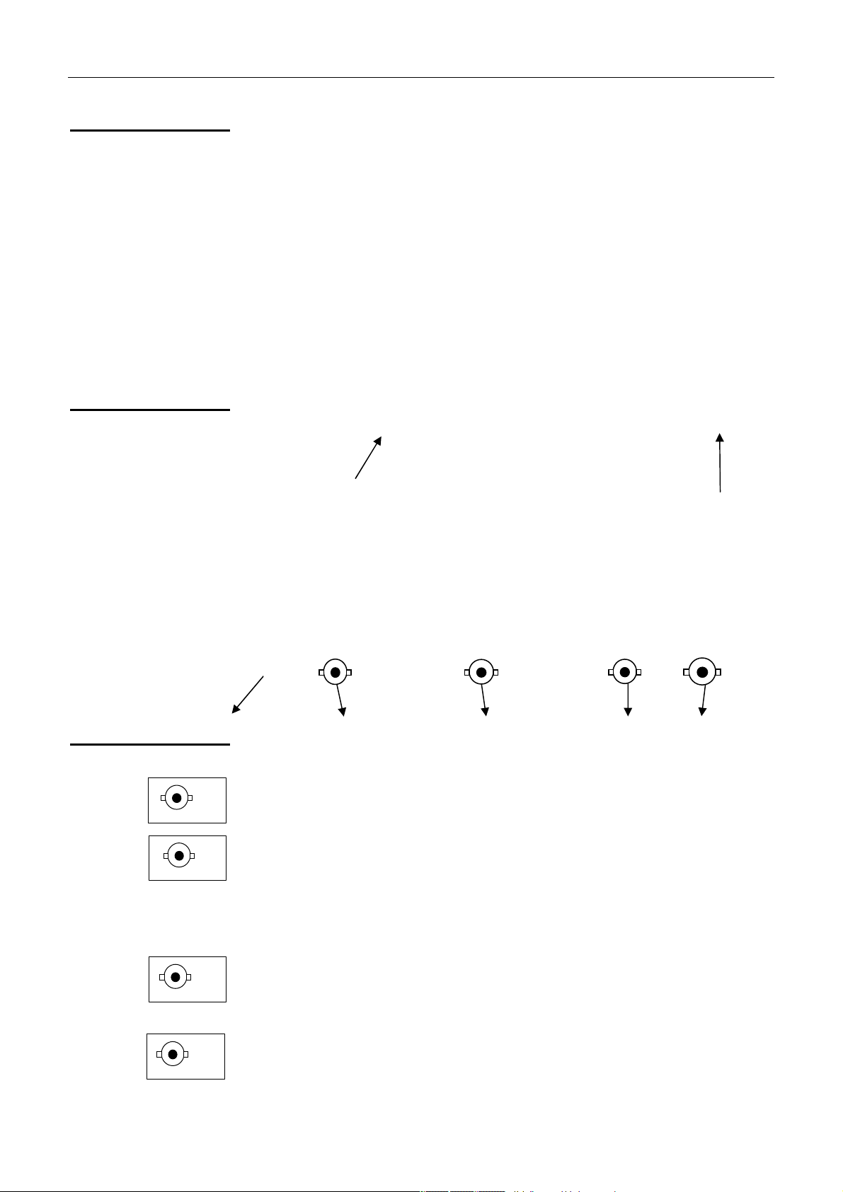
MAIN OUT
- Main output
VCF IN
- SWEEP input pilot signal in EXTernal source
SWEEP OUT
- Pilot output signal for INTernal SWEEP
TTL OUT
- TTL output
FREQ EXT
Frequency meter input
-
www.GlobalTestSupply.com
Page 7

GX 305 and GX 310 Description
GX 310 Description (contd.)
Back face
GX 305
Working voltage indicator
Network connection
Display
GX 310
GX 310P
USB type B connection
Working voltage indicator
Network connection
Find Quality Products Online at: sales@GlobalTestSupply.com
Function Generators II - 7
www.GlobalTestSupply.com
Page 8
GX 305 and GX 310 Description (contd.)
Wave selection:
• Sinusoidal
• square
• logic
• triangle
• continuous
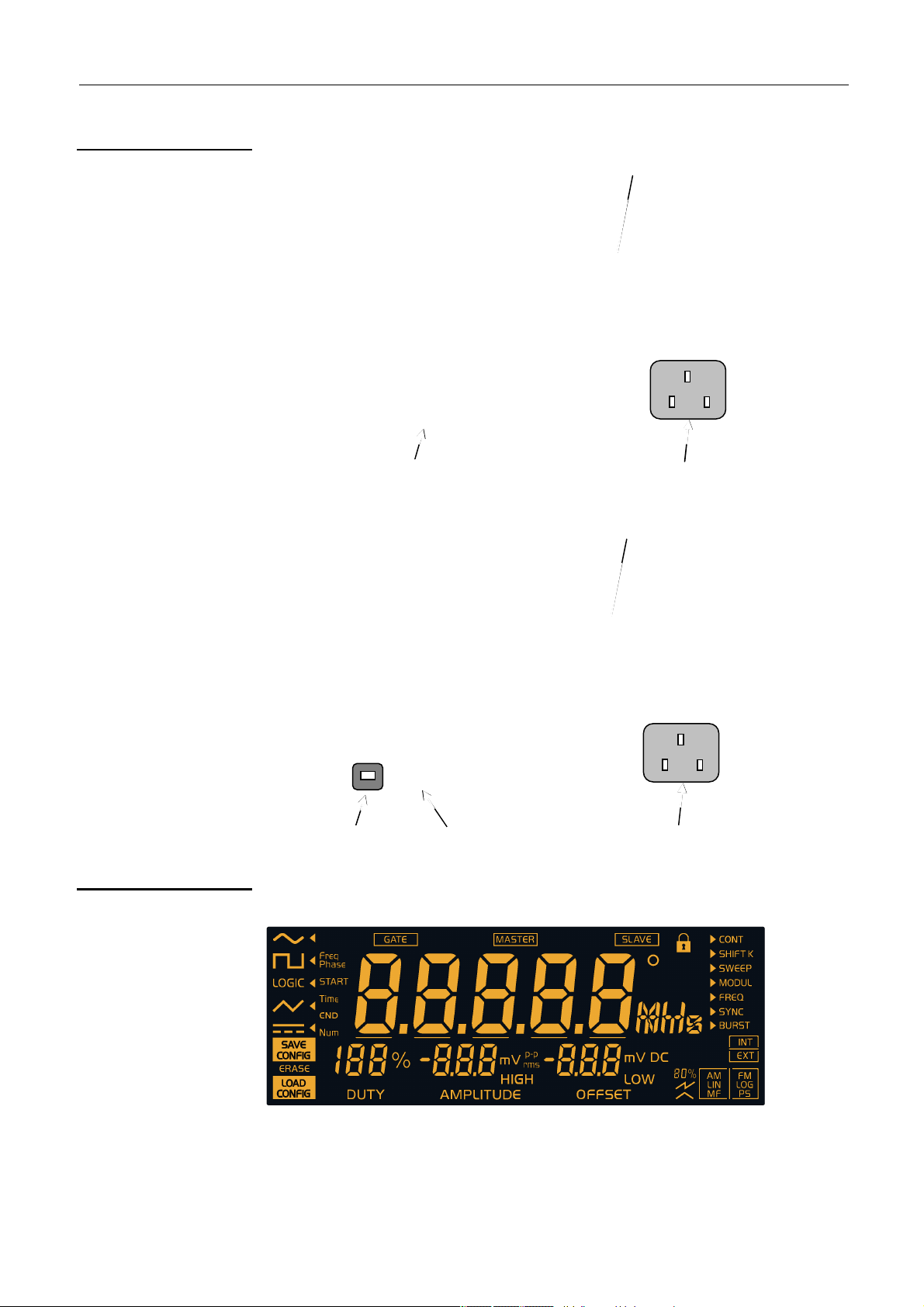
Indication of the displayed frequency:
• Freq, Freq
• Time (sweep interval)
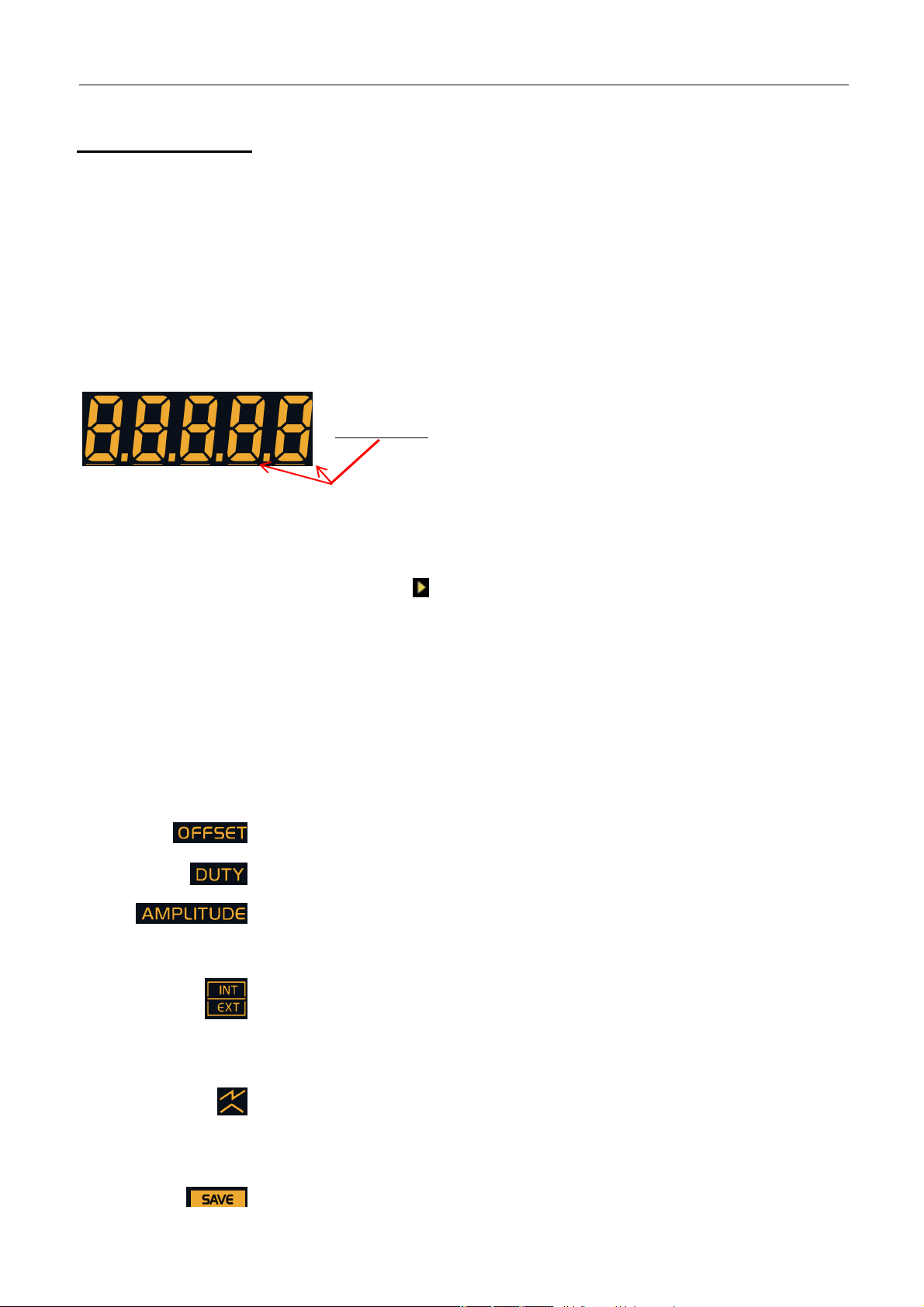
Frequency display (digit height: 20 mm)
Underscores: Indication of the digit to which the wheel
Unit of measure display
• degree
• MHz, kHz, Hz
• seconds
START
or Freq
END
increments apply during adjustment.
GX 305 and GX 310 Description
Function selection: current function indicator
• continuous
• sweep
• frequency
Duty cycle value display
Display of the amplitude value
Display of the offset value or the DC level
OFFSET display
DUTY display
AMPLITUDE display
Logical HIGH / LOW display
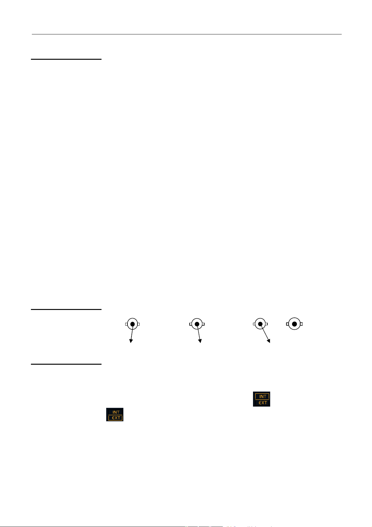
INTernal / EXTernal source selection
LINear / LOGarithmic sweep display
Sawtooth or triangle type sweep
Indication that the MODE key is assigned:
• to trigger the adjustment step when calibrating
• to trigger the selected test in Autotest
During calibration the is assigned to saving the parameters.
Find Quality Products Online at: sales@GlobalTestSupply.com
II - 8 Function Generators
www.GlobalTestSupply.com
Page 9

GX 305 and GX 310 Description
GX 305 and GX 310 Description (contd.)
Keys
The keys with the symbol have a specific action when pressed for more
than 1 second.
• The white keys may have a backlight:
Appliance under power but not turned on
Appliance turned on
MAIN OUT
Key lit MAIN OUT exit activated
• The other keys can be:
keys not assigned to the wheel adjustment or
unlit
having no action
the corresponding adjustment is assigned to the
lit
wheel.
the corresponding adjustment can be assigned to
blinking
the wheel.
Each time the WAVEFORM or FUNCTION is changed the keys that can be
assigned to the wheel adjustment blink for 4 seconds; if no keys are used
at this time the frequency adjustment (Freq or Freq
wheel.
) is assigned to the
START
Keys pressed for
less than 1 second
MAIN OUT
Sinusoidal waveform selection
Selects square or logical waveform by successive pressing on the key
Triangular waveform selection or saves adjustments during calibration
Continuous waveform selection
Validation, or not, of the waveform on the MAIN OUT BNC
Adjustment of the duty cycle using the wheel (square, triangle)
Adjustment of the output signal amplitude using the wheel
• Offset adjustment using the wheel
• DC level adjustment if the continuous waveform is selected.
Find Quality Products Online at: sales@GlobalTestSupply.com
Function Generators II - 9
www.GlobalTestSupply.com
Page 10

GX 305 and GX 310 Description (contd.)
Keys pressed for
less than 1 second
(contd.)
GX 305 and 310 Description
LOGIC LEVEL
FUNCTION
LOGIC waveform selected:
Adjustment of the high or low signal level using the wheel
FUNCTION keys:
Selection of one of the three available functions
SWEEP selection of the INTernal or EXTernal command signal
• SWEEP activated: selection of LIN or LOG sweep
• calibration: triggering of the selected adjustment step
• Autotest: run the selected test
SWEEP function activated in INT: assignment of the desired duration setting
for carrying out the sweep using the wheel.
Then, by pressing several times, selection of the digit on which to increment.
Division or multiplication by 10 of the current frequency value (decade change)
• Assignment of frequency adjustment to the wheel.
Then, by pressing several times, selection of the digit on which to
increment.
• SWEEP function activated: same functions with Freq
requencies.
f
START
and Freq
END
Find Quality Products Online at: sales@GlobalTestSupply.com
II - 10 Function Generators
www.GlobalTestSupply.com
Page 11

GX 305 and GX 310 Description
GX 305 and GX 310 Description (contd.)
Keys pressed for
more than 1 second
Pressing the key for more than 1 second forces the duty cycle to 50%.
Pressing the key for more than 1 second switches from a peak to peak
amplitude display to an RMS (root mean square) display.
Pressing the key for more than 1 second forces the offset value to 0.
LOGIC LEVEL
Pressing the key for more than 1 second assigns the LCD contrast adjustment
to the wheel.
For the SWEEP function, pressing the key for more than 1 second switches
from Freq
These keys assign the selected frequency to the start or end of the current
range.
START
to Freq
and vice versa.
END
Ranges
Press > 1 Second
‘RANGE-’
Press > 1 second
‘RANGE+’
[0.001 Hz ; 0.01 Hz] 0.001 Hz 0.01 Hz
[0.01 Hz ; 0.1 Hz] 0.01 Hz 0.1 Hz
[0.1 Hz ; 1 Hz] 0.1 Hz 1 Hz
[1 Hz ; 10 Hz] 1 Hz 10 Hz
[10 Hz ; 100 Hz] 10 Hz 100 Hz
[100 Hz ; 1 kHz] 100 Hz 1 kHz
[1 kHz ; 10 kHz] 1 kHz 10 kHz
[10 kHz ; 100 kHz] 10 kHz 100 kHz
[100 kHz ; 1 MHz] 100 kHz 1 MHz
GX 305 [1 MHz ; 5 MHz]
GX 310 [1 MHz ; 10 MHz]
1 MHz
GX 305 5 MHz
GX 31010 MHz
Find Quality Products Online at: sales@GlobalTestSupply.com
Function Generators II - 11
www.GlobalTestSupply.com
Page 12
GX 320 Description
GX 320 Description
Presentation
Specifications
nt face
Fro
The GX 320 is a standard alternating signal generator, using the DDS (Direct Digital
Synthesis) technology. It may simulate the operation and the specifications of various
electronic systems. It also includes a frequency meter input. The GX 320E is remote
programmable via an USB or ETHERNET link.
- Wave form: sinusoidal, square, triangle, logical, TTL, continuous
- Wave frequency: 0.001 Hz to 20 MHz for the sinusoidal and square
0.001 Hz to 2 MHz for the triangle
- INT and EXT sweep: adjustable from 0.001 Hz to 20 MHz
- EXT frequency meter: from 5 Hz to 100 MHz
- AM modulation: internal (1 kHz) and external (< 5 kHz)
- FM modulation: internal (1 kHz) and external (< 15 kHz)
- Frequency Shift Keying FSK: internal (1 kHz) and external (< 1 MHz)
- Phase Shift Keying PSK : internal (1 kHz) and external (< 1 MHz)
- BURST function: internal or external (< 1 MHz)
- GATE function: external (< 2 MHz)
- Function to synchronise several generators
- 15 configurations can be saved and recalled
Back lit LCD display (124 x 43 mm)
Coding wheel
ON / STANDBY
1. 2. 3. 4.
Terminals
1.
2.
3.
4.
Find Quality Products Online at: sales@GlobalTestSupply.com
III - 12 Function Generators
MAIN OUT
- Main output
VCG IN
- External SWEEP, MODUL, SHIFT K, BURST piloting signal input
SYNC CTRL
- Master synchronisation output signal in SYNC function
- Slave synchronisation input signal in SYNC function
SWEEP OUT in SWEEP or SHIFT K INTernal source
- Sweep piloting output signal for FSK and PSK
TTL OUT
- TTL output
SYNC M CLK
- in SYNC function, master clock output
EQ EXT
FR
- Frequency meter input
SYNC S CLK
- in SYNC function, slave synchronisation clock input
GATE IN
- GATE piloting input signal
www.GlobalTestSupply.com
Page 13
GX 320 Description
connection
Network
Connection
working
Network
Conne
ct
ion
working
GX 320 Description (contd.)
Rear panel
GX 320
USB type B connection
Indication of the
voltage
Display
GX 320E
ETHERNET
Indication of the
voltage
USB type B
Find Quality Products Online at: sales@GlobalTestSupply.com
Function Generators III - 13
www.GlobalTestSupply.com
Page 14

GX 320 Description (contd.)
Signal selection:
• sinusoidal
• square
• logic
• triangle
• continuous
current waveform indicator
Display of the current frequency phase:
• Freq, Freq
• Phase, Phase
• Time (sweep period, pulse period)
• Num : number of pulses
START
Frequency display (digit height 20 mm)
and Freq
, Phase
START
GX 320 Description
END
END
Underscores:
Indicate to which digit the wheel increments apply during
adjustment.
Unit of measure display:
• degree
• MHz, kHz, Hz
• seconds
Function selection:
• continue
• Shift Key
• sweep
• modulation
• frequency meter
• synchronisation
• Burst
Current function indicator
Duty cycle value display
Amplitude value display
Offset value or DC level value display
OFFSET type display
DUTY type display
AMPLITUDE type display
Find Quality Products Online at: sales@GlobalTestSupply.com
III - 14 Function Generators
www.GlobalTestSupply.com
Page 15

GX 320 Description
GX 320 Description (contd.)
HIGH / LOW level logical type display
INTernal / EXTernal source selection
Mode display:
• AM / FM Modulation
• LINear / LOGarithmic sweep
• Master / Slave synchronisation
• Shift key Frequency / Phase
Indication that the MODE key is assigned:
• to triggering the adjustment step when calibrating
• to the manual triggering of a set of pulses in BURST mode
• to triggering the selected test in Autotest mode
Sawtooth or triangle sweep type
Modulation rate display AM 20 % or 80 %
GATE mode activated display
Master synchronisation activated display
Slave synchronisation activated display
For the synchronisation function: indicates that the frequency and phase
adjustment on the slave are restricted by the master.
• During calibration the key is assigned to saving the settings.
• In normal mode selects save configuration mode
Selects configuration recall mode
Selects configuration clearing mode
Find Quality Products Online at: sales@GlobalTestSupply.com
Function Generators III - 15
www.GlobalTestSupply.com
Page 16

GX 320 Description
GX 320 Description (contd.)
Keys
Keys with the symbol have a specific action when pressed for more than
1 second.
• The white keys may have a back light:
MAIN OUT
MAIN OUT
• The other keys can be:
unlit
lit
blinking
Appliance under power but not turned on (red)
Appliance turned on (green)
Key lit MAIN OUT exit activated
Blinking key MAIN OUT and GATE functions activated
keys not assigned to the wheel adjustment or having no
action
the corresponding adjustment is assigned to the wheel.
the corresponding adjustment can be assigned to the
wheel.
Keys pressed for
less than 1 second
WAVEFORM
Each time the WAVEFORM or FUNCTION is changed the keys that
can be assigned to the wheel adjustment blink for 4 seconds; if no
keys are used at this time the frequency adjustment (Freq or
Freq
WAVEFORM keys:
Selects the waveform to be generated
Saves the current configuration or saves the settings when calibrating
Recalls or clears a saved configuration
) is assigned to the wheel.
START
Find Quality Products Online at: sales@GlobalTestSupply.com
III - 16 Function Generators
www.GlobalTestSupply.com
Page 17

GX 320 Description
GX 320 Description (contd.)
Keys pressed for
less than 1s (contd.)
LOGIC LEVEL
FUNCTION
Validation or not of the wave on the MAIN OUT BNC.
Adjustment of the wave duty cycle (square, triangle) using the wheel.
Adjustment of the output wave amplitude using the wheel.
• Offset adjustment using the wheel.
• Adjustment of the DC level if the continuous waveform is selected.
LOGIC waveform selected: adjustment of the high or low wave level using the
wheel.
FUNCTION keys:
Selection of one of the 7 available functions.
SHIFT K, or SWEEP, or MODUL or BURST functions activated: selection of
the INTernal or EXTernal command signal.
• SHIFT K o
a specific function mode (see Function list and adjustment paragraph).
• BURST function and EXTernal source activated: manual triggering of a
set of pulses.
• calibration: triggers the selected adjustment step.
• Autotest: triggers the selected test.
• SWEEP activated with INTernal source: assignment of the wheel to the
desired timing adjustment to carry out a frequency sweep; then, by
pressing several times, selection of the digit on which to apply the
increment.
• BURST function active: assignment of the wheel to the adjustment of the
number of pulses or the burst generation period (INT source); then, by
pressing several times, selection of the digit on which to apply the
increment.
Division or multiplication by 10 of the current frequency value (decade change).
• Assignment of frequency adjustment to the wheel; then, by pressing
several times, selection of the digit on which to apply the increment.
• SWEEP or MODUL FM or FSK activated: same functions with the
FreqSTART and Freq
r SWEEP or MODUL or SYNC functions activated: selection of
frequencies.
end
• SYNC function activated: adjustment of the de-phasing between the two
generators using the wheel.
• PSK function activated: by pressing several times, adjustment of the
PhaseSTART or Phase
Find Quality Products Online at: sales@GlobalTestSupply.com
Function Generators III - 17
www.GlobalTestSupply.com
using the wheel.
end
Page 18

GX 320 Description (contd.)
Keys pressed for
more than 1 second
Pressing for more than 1 second sets the GATE function.
Pressing for more than 1 second forces the duty cycle to 50 %.
Pressing the key for more than 1 second switches from a peak to peak
amplitude display to an RMS (root mean square) display.
Pressing the key for more than 1 second forces the offset value to 0.
LOGIC LEV EL
LOGIC LEVE L
LOGIC LEVE LLOGIC LEVE L
Pressing the key for more than 1 second assigns the LCD contrast adjustment
to the wheel.
GX 320 Description
BURST function activated, INTernal source. Pressing the key for more than 1
second is used to switch the number of pulses Num in the pulse generation
period Time, and vice versa.
These keys assign the selected frequency to the start or end of the current
range.
Ranges
[0.001 Hz ; 0.01 Hz] 0.001 Hz 0.01 Hz
[0.01 Hz ; 0.1 Hz] 0.01 Hz 0.1 Hz
[0.1 Hz ; 1 Hz] 0.1 Hz 1 Hz
[1 Hz ; 10 Hz] 1 Hz 10 Hz
[10 Hz ; 100 Hz] 10 Hz 100 Hz
[100 Hz ; 1 kHz] 100 Hz 1 kHz
[1 kHz ; 10 kHz] 1 kHz 10 kHz
[10 kHz ; 100 kHz] 10 kHz 100 kHz
Press > 1 Second
‘RANGE-’
Press > 1 second
‘RANGE+’
[100 kHz ; 1 MHz] 100 kHz 1 MHz
[1 MHz ; 10 MHz] 1 MHz 10 MHz
[10 MHz ; 20 MHz] 10 MHz 20 MHz
For the SWEEP or MODUL FM or FSK functions pressing the key for more
than 1 second is used to switch between Freq
Find Quality Products Online at: sales@GlobalTestSupply.com
III - 18 Function Generators
www.GlobalTestSupply.com
START
and Freq
and vice versa.
END
Page 19

General Commands
General Commands
Commissioning
Check that your instrument is compatible with the mains network voltage
(see the label at the back of the instrument), that the power supply cable
is not damaged and that it is earthed.
The power supply cable plug is used as a cut off point, connect the device
to a mains outlet that is easily accessible and is earthed in order to
ensure safety.
Four start-up modes are possible depending on the key
keys - used:
1. Normal Mode:
The instrument starts up using the last used configuration. By default the
factory configuration is restored.
The key becomes:
2. Version Mode:
– or combination of
FUNCTION
+
MAIN OUT
+
The instrument starts up in Version mode and displays the current software
version number and date.
+
The key becomes: (See Display of the software version).
3. Calibration Mode
The instrument starts up in Calibration mode with the selection of the
calibration to be run: automatic mode CAL_AU, by default.
The key becomes: (See automatic calibration).
4. Autotest Mode:
The instrument starts up in Autotest mode with the selection of the test to
be run: automatic mode tSt_AU by default.
The key becomes: (See Autotest).
:
Find Quality Products Online at: sales@GlobalTestSupply.com
Function Generators IV - 19
www.GlobalTestSupply.com
Page 20

General Commands
General Commands (contd.)
Stop
Whatever the mode, pressing this key puts the instrument on STANDBY.
When pressed while in Normal mode the context is saved:
- current settings in use for signal generation when the instrument was
stopped,
- settings for other functions that may have been changed.
The key becomes:
Each time Normal mode start-up is used all the settings are reloaded.
In the event of a power failure (or if the power cable is unplugged …), the
instrument restarts using the last backup (backup made the last time the device
was turned off using the ON/STANDBY key).
In the event of an error the default configuration is loaded:
• Signal sinusoidal
• Function CONTinuous
• Frequency 1 kHz
• Amplitude 1 Vpp
• Offset 0 V
• Output MAIN OUT ON not active
• No adjustments assigned to the wheel.
Activating the
N OUT terminal
MAI
MAIN OUT
MAIN OUT
The key becomes: .
At start-up the MAIN OUT terminal is always de-activated.
Pressing the key activates the terminal and the key lights: .
On the GX 320: the key may blink when the GATE function is activated (see
GATE function).
De-activation of the MAIN OUT terminal, the key is no longer lit: .
Find Quality Products Online at: sales@GlobalTestSupply.com
IV - 20 Function Generators
www.GlobalTestSupply.com
Page 21

General Commands
n the 4 seconds following the function validation the wheel is
General Command (contd.)
Setting the screen contrast
LOGIC LEVEL
1s or 1s
Selection of the
instrument function
FUNCTION
The display shows: .
The key becomes:
Adjustment of the contrast value from 0 to 99 using the coding wheel.
Exiting from this mode is made by pressing another key. The frequency display
returns to the screen and the possible associated keys blink.
The key becomes: .
The contrast value is memorised in the device configuration once it is turned off
(see left margin) or when the configuration is saved (GX 320).
Pressing once displays the list of functions available on the device in the top
.
FUNCTION
right hand corner:
The cursor indicates the selected function.
Pressing again moves the cursor towards the top or bottom to select another
function.
If, after 2 seconds, no keys have been pressed or when another key is pressed,
the selected function is validated and is the only one remaining displayed:
When the function has been validated the keys that can be assigned to the
wheel blink until one of them is selected; the key then lights up.
If no keys are used i
automatically assigned to frequency setting
(Freq or Freq
depending on the function).
START
(GX 310) (GX 320).
Find Quality Products Online at: sales@GlobalTestSupply.com
Function Generators IV - 21
www.GlobalTestSupply.com
Page 22

General Commands
General Commands (contd.)
Software version display
+
The following screen is displayed:
i.e. the 23rd November
for version number: 1.00
for the version date:
2008
Exit Version mode.
The key becomes: .
for GX 305
for GX 310
for GX 320
for Programmable
Automatic calibration
Calibration mode
FUNCTION
+
Entering
The device has an automatic function that can be used to calibrate signal
generation.
This function can be triggered:
- automatically (all settings are run automatically) or
- manually (individual selection and run of settings).
No specific wiring is needed for this function.
For optimal calibration the device must be at operating temperature
(switched on for 30 minutes) before running calibration.
In addition, when in manual mode it is recommended to respect the
running order of the calibration steps.
Entry into this mode is the CAL.AU. automatic mode. The display is as below:
Switching to manual mode is done by turning the wheel and selecting the
calibration step to be run individually.
Find Quality Products Online at: sales@GlobalTestSupply.com
IV - 22 Function Generators
www.GlobalTestSupply.com
Page 23

General Commands
that the adjustment settings may have changed and
General Commands (contd.)
Selecting the calibration step to run:
• CAL.AU : automatic calibration (all settings are triggered automatically)
• CAL.00 : cancels offsets for sine and triangle signals
• CAL.01 : cancels offsets for square and LOGIC signals
• CAL.02 : calculates gains for the DC level offset setting
• CAL.03 : cancels the secondary offset for square and LOGIC signals
• CAL.04 : calculates gains for amplitude setting for sine, triangle, square
and LOGIC
• CAL.05 : calibrates the duty cycle for square and LOGIC
• CAL.06 : sets AM and FM external modulation
• CAL.07 : sets AM modulation for square and LOGIC signals
Running
adjustments
(GX 305/310)
(GX 320)
Pressing the key triggers automatic calibration or the selected calibration step.
The display shows:
for automatic (then the adjustments are
displayed in order) or
in manual mode.
At the end of the run two situations are possible: the adjustment either succeeded
or failed.
If the adjustment succeeded the display shows:
in automatic or
in manual.
The display indicates
that the changes can be saved.
Find Quality Products Online at: sales@GlobalTestSupply.com
Function Generators IV - 23
www.GlobalTestSupply.com
Page 24

General Commands
General Commands (contd.)
Saving settings
(GX 320)
(GX 305/310)
Calibration mode
Exit from
In the event of an error the automatic calibration stops at the step in error, it
then switches to manual mode.
The display shows:
In the event of repeated errors contact your CHAUVIN-ARNOUX representative
(see p. 5).
Pressing saves the calibration.
The display is cleared once the backup is made. It reappears if the
calibration is changed.
Exit this mode using this key.
The key becomes: .
To save settings a data backup should be made (see abo
exiting the mode, otherwise the settings are lost and the previous
settings are re-loaded at start-up.
ve) before
Find Quality Products Online at: sales@GlobalTestSupply.com
IV - 24 Function Generators
www.GlobalTestSupply.com
Page 25

General Commands
General Commands (contd.)
Instrument Autotest
Wiring needed
The device has an automatic electronics test function. This feature can be run
automatically (all tests run automatically) or manually (individual selection and
running of tests).
These tests require specific wiring of the device’s input/output terminals.
Two wirings are needed.
When needed they are indicated by the following messages:
for wiring n° 1:
(GX 305/310)
(GX 320)
(GX 305/310)
(GX 320)
for wiring n° 2:
(GX 305/310)
(GX 320)
Once the wiring has been made pressing the key continues the test.
Find Quality Products Online at: sales@GlobalTestSupply.com
Function Generators IV - 25
www.GlobalTestSupply.com
Page 26

General Commands
scrolls through all segment, even segment, odd segment
General Commands (contd.)
Entering
AUTOTEST mode
MAIN OUT
+
(GX 305/310)
MAIN OUT
+
(GX 320)
By default this mode is entered using the automatic mo
the following:
Switching to manual mode is done by turning the test step selection wheel and
running individually.
Selection of the test step to run:
• tSt.AU : automatic test (all tests automatically sequenced)
• tSt.00 : LCD test (
displays by pressing the MODE key)
• tSt.01: keyboard and key light test
(you must press all the keys except , each time a key is
pressed an LCD segment is cleared).
N° 1 wiring is needed:
• tSt.02: frequency meter test
• tSt.03: GATE IN test (GX 320)
• tSt.04: CTRL IN test using SYNC function (GX 320)
• tSt.05: FM modulation test (GX 320)
• tSt.06: external AM test (GX 320)
• tSt.07: Reset DDS pilot test
• tSt.08: DDS FS register pilot test (frequency commutation)
• tSt.09: DDS PS register pilot test (phase commutation)
• tSt.10: triangle duty cycle test
N° 2 wiring needed:
• tSt.11 : CTRL OUT test using SYNC function (GX 320)
• tSt.12 : SWEEP OUT test
de tSt.AU. The display is
Find Quality Products Online at: sales@GlobalTestSupply.com
IV - 26 Function Generators
www.GlobalTestSupply.com
Page 27

General Commands
in automatic mode (then scrolls through
General Commands (contd.)
Running the tests
Pressing the key triggers the automatic test or the selected test step.
The display shows:
(GX 310)
(GX 320)
the tests) or
At the end of the run 2 situations are possible: the test was successful or the test
failed.
in manual mode.
If the test succeeded the display shows:
in automatic mode or
in manual mode.
If the test failed the automatic test stops at the failed test step or switches to
manual mode. The display shows:
If the error persists contact your MANUMESURE representative (see p. 5).
Exiting AUTOTEST
Pressing this key exits Autotest mode.
The current test is stopped and the instrument switches to STANDBY, the key
becomes:
Find Quality Products Online at: sales@GlobalTestSupply.com
Function Generators IV - 27
www.GlobalTestSupply.com
.
Page 28

General Commands (contd.)
Saving a configuration (GX 320)
The GX 320 can save and reload user configurations.
A total of up to 15 files can be saved.
This backup is permanent (the data is saved even if the instrument is powered
down).
Enters the configuration management mode.
is displayed on the screen with the current file number:
General commands
if file 3 is empty;
if file 3 already contains a configuration
the data (other than frequency) is displayed on the screen.
Pressing another key than or exits the mode without saving.
Selects files from SEt.01 to SEt.15. The screen is updated with the data from
the selected file.
Pressing the key again saves the current configuration in the selected file.
The display returns to its pre-backup status and the display is cleared.
When saving the content of the selected file is overwritten by the content
of the current configuration without any warning messages.
Find Quality Products Online at: sales@GlobalTestSupply.com
IV - 28 Function Generators
www.GlobalTestSupply.com
Page 29

General Commands
General Commands (contd.)
Reloading a configuration (GX 320)
The GX 320 can reload 16 saved configurations:
• 15 user configurations,
• plus the default configuration (“factory” configuration see §. Stop).
Entering configuration reload mode.
is displayed on the screen with the current file number:
if file 3 is empty.
if file 3 contains a configuration the data
(except frequency) is displayed on the screen.
Pressing a key other than exits the mode without making any changes.
Selects a file from SEt.00 to SEt.15 (Set.00 is the factory configuration). The
screen is updated using the data from the selected file.
Pressing the key again reloads the configuration from the selected file.
If the file is empty or inconsistent the operation is cancelled:
• the settings used before the reload operation are maintained,
• the initial display is shown.
If the selected file is valid the configuration it contains is loaded and the display
is updated with its data.
is no longer displayed indicating that the configuration reload mode has
been exited.
Find Quality Products Online at: sales@GlobalTestSupply.com
Function Generators IV - 29
www.GlobalTestSupply.com
Page 30

General Commands (contd.)
Clearing a configuration (GX 320)
Clearing a user configuration file (Set.01 to Set.15) consists in saving a null
configuration in the file.
This configuration is shown by displaying the file number only during file
selection.
Reloading a null configuration has no effect (the existing settings are kept
active).
General commands
It is not necessary to clear a file before saving a con
saving the configuration overwrites the data in the file.
Enters configuration mode.
is displayed with the current file number:
if file 3 is empty
if file 3 already contains a configuration
the data (except frequency) is displayed on the screen.
Pressing a key other than
changes.
or exits the mode without making any
figuration since
Selects file erase mode.
is added to the display:
Pressing the key again unselects the file erase mode.
Selects a file from SEt.01 to SEt.15. The screen is updated with the data from
the selected file.
Pressing the key again saves a null configuration in the selected file and returns
to the current configuration display.
and are cleared from the screen.
Find Quality Products Online at: sales@GlobalTestSupply.com
IV - 30 Function Generators
www.GlobalTestSupply.com
Page 31
Generation of basic periodic signals
Generation of basic “CONTinous” periodic signals
Available output waveforms
Waveform selection
GX 305/310
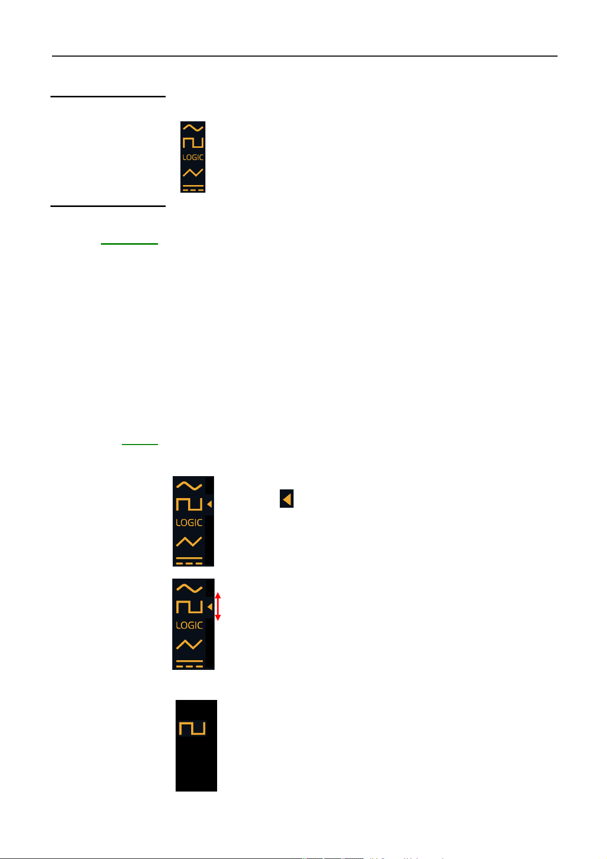
The instrument generates the following waveforms:
• sine
• square
• TTL logic
• triangular
• continuous.
Sine waveform
Square waveform
Logic output waveform
Triangular waveform
Continuous waveform
GX 320
WAVEFORM
WAVEFORM
Each time a key is pressed the symbol is displayed on the screen and the keys
that can be assigned to the wheel blink.
Pressing once displays the list of available waveforms at the top left of the screen:
The cursor indicates the current waveform.
Pressing again moves the cursor up or down to select a new
waveform.
If the keys are not pressed for 2 seconds or if another key is pressed the
selected waveform is validated and remains displayed:
When the waveform is validated the keys that can be assigned to
the wheel blink until one of them is selected; this key is then lit.
If no key is pressed within 4 s of validation the wheel is
automatically assigned to frequency adjustment (Freq or
Freq
Find Quality Products Online at: sales@GlobalTestSupply.com
Function Generators V - 31
www.GlobalTestSupply.com
START
).
Page 32

Generation of basic periodic signals
Generation of basic “CONT” periodic signals (contd.)
Adjusting signal frequency
Entering the
5 significant digits
or
Frequency is set in two steps:
• Entry of the five significant digits
• Setting the decimal point and the unit multiplier
The coding wheel and the following key can be used to enter the 5 significant
di
gits.
Assign frequency setting to the wheel. The:
Value adjustment.
By pressing several times, the digit from which wheel increments are added is
selected.
key lights.
By default the digit to which increments are applied is the unit digit
(extreme right). This setting is programmed each time the instrument
is started up.
Positioning the
decimal point and
the unit multiplier
Entry short cuts
1s
1s
These keys position the decimal point and the unit multiplier.
Assigns the minimum value for the current range
(see Pressing keys for more than 1 second in the GX description paragraph).
Assigns the maximum value for the current range
(see Pressing keys for more than 1 second in the GX description paragraph).
Find Quality Products Online at: sales@GlobalTestSupply.com
V - 32 Function Generators
www.GlobalTestSupply.com
Page 33

Generation of basic periodic signals
Generation of basic CONT periodic signals (contd.)
Example 1:
1st possibility
The wheel is not assigned to a setting (FREQ not lit or blinking),
the current frequency value is: .
We want to enter: .
The FREQ key lights: .
The display shows:
The display shows: .
The display shows: .
25
2nd possibility
The display shows: .
The display shows: .
The display shows: .
The FREQ key lights: .
The display shows: .
The display shows: .
Find Quality Products Online at: sales@GlobalTestSupply.com
Function Generators V - 33
www.GlobalTestSupply.com
Page 34

Generation of basic periodic signals
Generation of basic “CONT” periodic signals (contd.)
The display shows: .
2
The display shows: .
The display shows: .
5
3rd possibility
2500
Example 2:
The display shows: .
The FREQ key lights.
The display shows:
The display shows: .
The display shows: .
The wheel is not assigned to any settings (FREQ key unlit),
the current frequency value is: .
.
We want to enter: .
The FREQ key lights: .
1s
The display shows:
Find Quality Products Online at: sales@GlobalTestSupply.com
V - 34 Function Generators
www.GlobalTestSupply.com
.
Page 35

Generation of basic periodic signals
Generation of basic “CONT” periodic signals (contd.)
Setting the duty cycle
or
The duty cycle can only be adjusted for square, logic or triangle forms using the
“CONTinuous” function.
The setting can be limited depending on the signal frequency.
Signal Frequency Possible adjustments
Square
Logical
Triangle
Assignment of the duty cycle to the wheel. The key lights: .
Setting the value.
≤ 200 kHz
200 kHz < F ≤ 1 MHz
F > 1 MHz
F < 0.2Hz
0.2Hz ≤ F ≤ 1 kHz
1 kHz < F ≤ 10 kHz
F > 10 kHz
10 to 90 %
20 to 80 %
50 %
50%
10 to 90 %
30 to 70 %
50 %
Setting the signal
litude
amp
or
Vpp/Vrms display
1s
1s
Forces the duty cycle value to 50 %.
The duty cycle is limited by the frequency, turning the wheel may have no
effect.
Amplitude indications are given in open circuit.
Under 50
Assignment of amplitude adjustment to the wheel. The key lights: .
Adjustment of the Vpp or Vrms value depending on the selected display.
Switches from Vpp to Vrms display and vice versa
The variation is from 0 to 20 Vpp in open circuit.
ΩΩΩΩ
, amplitudes are divided by 2.
The sum of continuous voltage + alternating voltage cannot be >>>> ± 10 V.
Find Quality Products Online at: sales@GlobalTestSupply.com
Function Generators V - 35
www.GlobalTestSupply.com
Page 36

Generation of basic periodic signals
Generation of basic “CONT” periodic signals (contd.)
Setting the offset and DC level
or
1s
Setting signal logical levels
or
Assignment of offset adjustment to the wheel. The key lights.
Value adjustment.
The variation field is from -10 V to +10 V maximum in an open circuit.
Forces the offset value to 0.
The sum of continuous voltage + alternating voltage cannot be >>>> ± 10 V.
This function is only available if the “LOGIC” waveform has been selected.
Assignment of the logic signal low level to the wheel.
The key lights.
The "Adj.LO" message displays instead of the frequency value:
By pressing several times the high or low level is selected, "Adj.HI" is displayed
for high level adjustment:
Adjustment of the selected value.
The field of variation for these levels is from -10 V to +10 V by 100 mV intervals.
high level is always greater than or equal to the low level.
The
Find Quality Products Online at: sales@GlobalTestSupply.com
V - 36 Function Generators
www.GlobalTestSupply.com
Page 37

Fonction SHIFT K
TTL output
Shift Keying function “SHIFT K” (GX 320 only)
The SHIFT KEY function can work with the signal frequency (FSK) or phase
(PSK):
- “FSK” is a frequency commutation piloted either INTernally or EXTernally:
switching from Freq
START
to Freq
and vice versa.
END
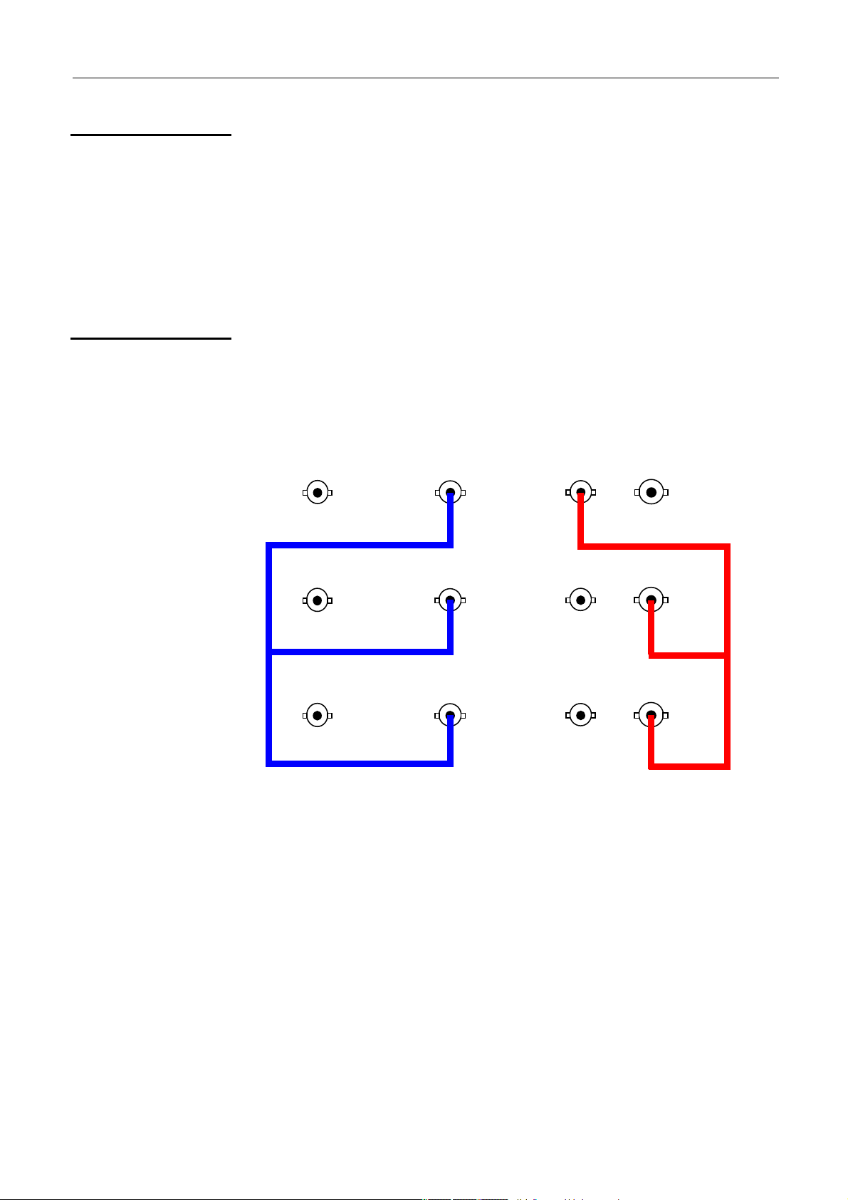
INTernal FSK:
Channel1: MAIN OUT
Channel2: VCG IN Sweep out
Connections
- “PSK” is a phase jump with value Phase
START
and Phase
, piloted by a
END
command signal that can be INTernal or EXTernal.
INTernal PSK
Channel1: MAIN OUT
Channel2: VCG IN Sweep out
:
At each change in signal status the programmed phase value (Phase
Phase
is added to the current phase.
END)
• With an INTernal source the command signal has a frequency of 1 kHz. It
can be viewed on the generator SWEEP OUT terminal.
• With an EXTernal source the pilot signal is a TTL signal (0 - 5 V) with a
frequency of < 1 MHz from the generator VCG IN terminal.
Main output signal
TTL input command signal from an
EXTernal F < 1 MHz
Output command signal from an
INTernal source
signal
START
or
FSK mode selection
Pressed successively, “F” mode selection (Frequency).
PSK mode selection
Pressed successively, “P” mode selection (Phase).
Selection of the source
Pressed successively, source selection:
INTernal
or
EXTernal .
Find Quality Products Online at: sales@GlobalTestSupply.com
Function Generators VI - 37
www.GlobalTestSupply.com
Page 38

SHIFT K Function
Shift Keying “SHIFT K” function (contd.)
Setting frequencies in FSK mode
or
1s or 1s
1s
Setting phases in PSK mode
or
Freq
display and assignment of adjustment to the wheel.
START
The key lights: .
Freq
display and assignment of adjustment to the wheel.
END
The key lights: .
Pressed successively selects the digit from which the increment will be
applied.
Adjustment of the selected value.
Passage from Freq
adjustment to Freq
START
adjustment.
END
Assignment of Phase
adjustment to the wheel.
START
The key lights: .
1s or 1s
Assignment of Phase
The key lights: .
Adjustment of the selected value.
e field of phase variation is of -180° to +180° b y intervals of 1°.
Th
Pressed successively assigns Phase
wheel.
1s
Other settings
Forces the phase being set to 0.
See “CONT” function.
adjustment to the wheel.
END
or Phase
START
adjustment to the
END
Find Quality Products Online at: sales@GlobalTestSupply.com
VI - 38 Function Generators
www.GlobalTestSupply.com
Page 39

SWEEP Function
SWEEP frequency scan function
Connections
Remarks
SWEEP is a frequency scan from Freq
START
to Freq
piloted:
END
•either INTernally by the generator following a linear or logarithmic formula
and a saw tooth or triangle variation.
The user can choose a scan time from 10 ms to 100 s.
•either EXTernally using a voltage of ± 10 V applied to VCF IN (GX 305/310)
or VCG IN (GX 320) with a frequency < 15 kHz.
•Depending on the values of Freq
in ascending or descending order.
be
START
and Freq
the frequency scan will
END
When using EXTernal SWEEP the signal level is read at a frequency of 60 kHz.
This amplitude (coded on 256 values) is then converted into frequency.
When using INTernal SWEEP, the scan is made using a maximum of 256
values.
Main
modulated
output signal
- in EXT: Pilot signal ± 10 V
- in INT: SWEEP OUT
Input:
TTL OUT
Selection of scan mode
Assignment
ence using
sequ
INTernal source
Pressed successively this key selects one of the following scan modes:
Display Description Channel1: MAIN OUT,
Channel2: SWEEP OUT
Linear rule,
triangular variation
Linear rule,
saw tooth variation
Logarithmic rule,
triangular variation
Logarithmic rule,
Saw tooth variation
Find Quality Products Online at: sales@GlobalTestSupply.com
Function Generators VII - 39
www.GlobalTestSupply.com
Page 40

SWEEP Function
)
SWEEP frequency scan function (contd.)
Assignment
sequence using
EXTernal source
INTernal source
EXTernal source
Display Description Channel 1:
MAIN OUT(F
Channel 2:
Modulation: SINE, 1 kHz, 10Vpp
Linear rule between
the command signal
and the generated
frequency
Logarithmic rule
between the command
signal and the
generated frequency
= 1 kHz, F
start
= 100 kHz
end
A SWEEP OUT signal is available on the VCF IN BNC (GX 305/310)
or VCG IN (GX 320).
It is a proportional signal with a generated frequency, amplitude from 0 to 2V.
The generated output frequency is proportional (according to a linear or
logarithmic rule) to the voltage on VCF IN (GX 305/310) or VCG IN (GX 320).
The command signal is sampled on 8 bits using a frequency of 60 kHz.
For -10 V: the output frequency F ≅ Freq
For 10 V: F ≅ Freq
END
START
Selecting the scan source
Setting the START / END frequencies
or
1s or 1s
Pressing the key successively selects the INTernal source or the
EXTernal source .
Displays Freq
and assigns adjustment to the wheel.
START
The key lights: .
Displays Freq
and assigns adjustment to the wheel.
END
The key lights: .
Pressing successively selects the digit from which the increment will apply.
Adjusts the selected value.
1s
Switches from setting Freq
to setting Freq
START
END
.
Find Quality Products Online at: sales@GlobalTestSupply.com
VII - 40 Function Generators
www.GlobalTestSupply.com
Page 41

SWEEP Function
SWEEP frequency scan function (contd.)
Setting the scan time using INTernal source
Displays the Time and assigns adjustment to the wheel.
or
Other settings
The key lights: .
Pressed successively selects the digit to which the increment will apply.
Adjusts the value using the wheel.
See the CONT function.
Find Quality Products Online at: sales@GlobalTestSupply.com
Function Generators VII - 41
www.GlobalTestSupply.com
Page 42
MODUL Function
MODUL Modulation function (GX 320 only)
The MODUL function modulates a carrier frequency (FM) or amplitude (AM).
The modulating signal can be:
• either internal (INTernal source, sinusoidal 1 kHz signal)
• or on VCG IN, for an EXTernal source.
The carrier specifications are defined in the same way as the CONT function.
Using an EXTernal source the signal must have an amplitude of ± 10 Vpp
and a frequency of < 15 kHz (FM) and < 5 kHz (AM).
Depending on the voltage the modulation is as follows:
- AM: the output signal amplitude is typically
100 % for -10 V
50 % for 0 V
null for 10 V
- FM: the output signal frequency is typically
Freq
(Freq
Freq
for -10 V
start
+ Freq
start
for +10 V
end
) / 2 for 0 V
end
Remarks • For AM: with LOGIC and square signals modulation is digital:
Connections
Selection of modulation source
the modulating signal is read at a frequency of 150 kHz. This
amplitude (256 values) pilots the output signal amplitude.
For the other types of signal modulation is analogue and the
modulating signal cannot exceed 5 kHz.
• For AM: with the SINE and TRIANGLE signals, TTL OUT is not available
• For FM: modulation is digital: the modulating signal level is read at a
frequency of 65 kHz.
This amplitude (256 values) is then converted into frequency.
Modulated output
signal
Pilot signal
± 10 V; F < 5 kHz
TTL OUT
Pressed successively selects the INTernal source or the EXTernal source
.
Find Quality Products Online at: sales@GlobalTestSupply.com
VIII - 42 Function Generators
www.GlobalTestSupply.com
Page 43

MODUL Function
MODUL Modulation function (GX 320 only, contd.)
Selection of the AM/FM modulation mode
Pressing successively selects the following modulation modes:
INTernal source
EXTernal source
Display Description
20% amplitude
modulation
80% amplitude
modulation
Frequency
modulation
Display Description
Amplitude
modulation
Frequency
modulation
Setting START / END FM frequencies
Displays Freq
or
and assigns adjustment to the wheel.
START
The key lights: .
1s or 1s
Displays Freq
and assigns the adjustment to the wheel.
END
The key lights: .
Pressed successively selects the digit to which the increment will be applied.
Adjusts the selected value.
Switches from setting Freq
1s
to setting Freq
START
END
.
Other settings
See CONT function.
Find Quality Products Online at: sales@GlobalTestSupply.com
Function Generators VIII - 43
www.GlobalTestSupply.com
Page 44

Fonction FREQ
Frequency meter function “FREQ”
Selecting the FREQ function activates measurement of the frequency of the
signal input to the FREQ EXT terminal.
The frequency meter can measure frequencies from 5 Hz to 100 MHz with the
following precision:
< 50 mV sensitivity F ≤ 30 MHz
< 60 mV sensitivity for 30 MHz < F ≤ 80 MHz
< 90 mV sensitivity for 80 MHz < F ≤ 100 MHz
The maximum amplitude (*) of the measured signal is:
300 V sensitivity from 5 Hz to 5 kHz
30 V sensitivity from 5 kHz to 1 MHz
10 V sensitivity above this value
(*) signal with a 50% duty cycle.
Measurement stabilisation time depends on the input frequency:
≤ 1 s from 5 to 20 Hz (≥ 1 measurements per second)
≤ 100 ms from 20 to 400 Hz (2 measurements per second)
≤ 40 ms from 400 Hz to 100 MHz (2 measurements per second)
Connections
Indication of the 300 V protection (50 - 60 Hz) CAT I
FREQ EXT terminal
for the measured
signal
Find Quality Products Online at: sales@GlobalTestSupply.com
VIII - 44 Function Generators
www.GlobalTestSupply.com
Page 45
SYNC Function
r
SYNC Synchronisation Function (GX 320 only)
The SYNC function is used to synchronise several GX 320 set up in a cascade
in order to create a variable phase multiple signal generator.
The frequency resolution of this function is: 37 mHz, the clock frequency of the
DDS is set at 10 MHz.
To limit the sampling effect the maximum frequency of the output signal is set at
100 kHz.
The Master generator supplies the Slave generators with the clock (Clk) used to
generate the signals (10 MHz) and a synchronisation signal (Ctrl). This allows
all the generators to start at the same time and control their phase offset.
Connections
Control signal (Ctrl): Connect the Slave VCG IN BNCs to the Master.
Clock signal (Clk): Connect the slave FREQ_EXT BNCs to the Maste
TTL OUT.
Master
Slave1
Slave2
Find Quality Products Online at: sales@GlobalTestSupply.com
Function Generators X - 45
ring signal generation disconnecting one of the Ctrl or Clk cables
Du
desynchronises the generators.
To resynchronise them use the master’s ‘MAIN OUT ON/OFF’ key to
deactivate and then reactivate signal generation.
www.GlobalTestSupply.com
Page 46
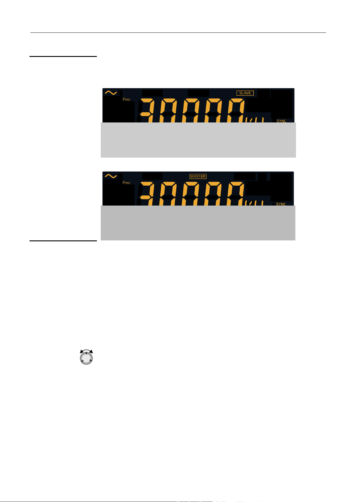
SYNC Function
SYNC Synchronisation Function (GX 320 only, contd.)
Selection of the Slave / Master mode
Pressed successively selects S mode (Slave):
or M (Master):
Adjusting phase offset
or
1s
Phase offset can be set on the master and on the slave (if it is not locked).
Whatever the mode selected (M/S) the phase offset is that of the slave(s)
related to the master.
The phase offset entered on the master is applied to all the slaves whereas the
phase offset entered on the slave is limited to that slave:
Phase offset (slave/master) = entered phase offset
Displays phase offset and assigns the adjustment to the coding wheel.
The key lights.
Value adjustment.
The phase is in degrees and can have values between -180° C and
+180° C, varying by 1°.
The master mode phase is reversed in relation to the slave mode.
Forces the phase to 0°
+ entered phasing
master
slave
Find Quality Products Online at: sales@GlobalTestSupply.com
X - 46 Function Generators
www.GlobalTestSupply.com
Page 47

SYNC Function
ster all adjustments are possible in real time because each
selecting waveform and adjusting frequency and phase are
SYNC Synchronisation Function (GX 320 only, contd.)
Activation of signal generation (Master)
MAIN OUT
On the ma
change in the master commands resynchronisation of all the slaves.
As this is not possible on the slaves, changing waveform, frequency
or phase are not possible when signal generation is activated. On the
other hand as amplitude and offset have no effect on synchronisation
they remain adjustable at all times.
The slave is said to be locked: is displayed on the top right hand
corner of the slave screen(s).
In order to change the waveform, frequency or phase on the slave
you must stop signal generation on the master using its ‘MAIN OUT
ON/OFF’ key.
• on the Master:
- Activates MAIN OUT and signal generation on all devices on which MAIN
OUT is activated.
The master key lights: .
- Locking slaves:
no longer possible on the slaves.
The symbol is dispayed on the slave screen as below:
MAIN OUT
Other settings
• on the slaves:
- Activation of the associated MAIN OUT (effective signal output is only
possible if signal generation is activated on the master).
The slave key lights: .
• on the Master:
- Deactivation of MAIN OUT and halting of signal generation on all devices.
The master key is turned off: .
- The master frees the slaves: waveform selection and frequency and phase
adjustment are now possible.
The symbol disappears from the slaves.
• on the Slaves: the associated MAIN OUT is deactivated.
The slave key is turned off: .
See the CONT function.
Find Quality Products Online at: sales@GlobalTestSupply.com
Function Generators X - 47
www.GlobalTestSupply.com
Page 48

SYNC Synchronisation function (GX 320 only, contd.)
SYNC Function
Example 1:
Generating three phase signals
Connect the three GX 320 generators as shown above (see Connections),
identify a master and 2 slaves and then programme the 3 devices with:
• the same frequency 1 kHz,
• the same amplitude 10 Vpp
• the same offset 0 V
• the same sine waveform
• phases 0° (master), +120° and -120°.
Activate the 3 MAIN OUTs.
On an oscilloscope view the output signals from the three devices:
Channel 1: master (0°)
Cha
nnel 2: slave1 (120°)
Channel 3: slave 2 (-120°)
Example 2:
Fourier synthesis
A simple illustration of generator synchronisation is the synthesis of a square
signal using its first harmonics.
The square signal is broken down as follows:
f(x) = 4/π (sinx+ sin3x / 3 + sin5x / 5 + sin7x / 7 + ... sinnx / n + ...)
ere n is always an odd number.
wh
To synchronise multiple frequencies the values programmed in the DDS must
also be multiple.
We are here faced with the problem of calculation rounding and programming
resolution: it is highly probable that the direct entry on F on the master and n*F
on the slaves will not give synchronous signals.
The DDS is programmed using a 28 bit register and is piloted by a 10 MHz
clock (in the SYNC function).
The DDS frequency resolution for this function is therefore:
10 MHz / 228 = 0.037 Hz, which means that for a frequency F entered the
resulting frequency is F ± 18.5 MHz.
The formula relating the user entered frequency to the value programmed in the
DDS is the following:
Val
= ENT((Frequency
DDS
with: ENT( ) function returning the whole part of the value
x 228) / DDS_Clock + 0.5)
(Hz)
DDS_Clock = 10 MHz,
adding 0.5 rounds the value.
Find Quality Products Online at: sales@GlobalTestSupply.com
X - 48 Function Generators
www.GlobalTestSupply.com
Page 49

SYNC Function
SYNC Synchronisation Function (GX 320 only, contd.)
Thus when you programme a frequency of 100 Hz, the programmed value is:
ENT((100*228)/107 + 0.5) = 2684 which is the equivalent of a frequency of
99.987 Hz (obtained by reverse calculation).
If you wish to programme a synchronous n*100 Hz multiple frequency you must
enter a frequency which results in a DDS programmed value of n*2684, or a
true frequency equal to n*99.987 Hz.
In our example we will generate a square 100 Hz signal using its first three
harmonics: 3 sinusoids with a frequency of 100 Hz, 300 Hz and 500 Hz and an
amplitude of A, A/3 and A/5.
For this example 3 GX 320 generators are needed:
- one Master: on which the SINE waveform is selected, amplitude 20 Vpp,
a null offset, a null phase and a frequency of 100 Hz
(or 99.987 Hz).
- Slave 1: on which the SINE waveform is selected, amplitude 6.7 V, a null
offset, a null phase and a frequency of 3*99.987 = 299.96 Hz.
- Slave 2: on which the SINE waveform is selected, amplitude 4 V, a null
offset, a null phase and a frequency of 5*99.987 = 499.93 Hz.
Connect the generators as shown in the Connections paragraph, activate the
ve outputs and then the master output (to ensure synchronisation do a
sla
master MAIN OUT OFF and then ON).
On the oscilloscope connect the device MAIN OUT (respectively Master, Slave1
and Slave 2) outputs on channels 1, 2, 3.
Select the same sensitivity of 5 V/div. on each channel (choose the weakest
frequency signal as trigger: channel 1).
On channel 4 carry out the sum of Channel1 + Channel2 + Channel3, and
observe the result:
A square signal forms: the higher the number of odd harmonics the better the
signal quality obtained.
Find Quality Products Online at: sales@GlobalTestSupply.com
Function Generators X - 49
www.GlobalTestSupply.com
Page 50

GATE function (GX 320 only)
ommand input
This function is only available with “CONT”, “SWEEP” and “MODUL”.
It superimposes a stop command for the alternating MAIN OUT signal
component over the current function, piloted by a TTL input to the BNC
FREQ EXT Gate in terminal.
When the TTL signal is at the 1 logical level (5 V), the alternating
component of the MAIN OUT terminal is cut.
At 0 level it is generated freely.
The GATE has no effect on the direct component of the signal.
The command takes effect in approximately 100 ns.
GATE Function
Channel 1: Main Out (sine, 1 kHz, 10 Vpp)
Channel 2: TTL Out
Channel 3: Gate In (LOGIC, 300 Hz, 10 V - 0 V)
Connections
GATE activation
MAIN OUT
1s
MAIN OUT
1s
GATE de-activation
MAIN OUT
1s
Main output
Function activation, the
TTL OUT
output
indication is displayed, the MAIN OUT
GATE c
signal
terminal remains activated
The key blinks:
.
Pressing the key for more than 1 second does not activate the MAIN OUT
terminal but only the GATE function :the key remains unlit.
Function is de-activated and the is cleared, the MAIN OUT terminal
remains active.
The key lights: .
MAIN OUT
Function de-activation and the
indication is cleared, the terminal is
still not activated: the key remains unlit.
1s
Remark
At each function change (CONT,
SHIFT K, SWEEP, MODUL, FREQ, BURST
or SYNC), the GATE function is de-activated.
Find Quality Products Online at: sales@GlobalTestSupply.com
XI - 50 Générateurs de Fonctions
www.GlobalTestSupply.com
Page 51

BURST Function
Num = n
umber of pulses
TTL
signal on
VCG_IN
BURST Pulse burst function (GX 320 only)
The BURST function generates sets of pulses:
• Using an INTernal source the user must enter a generation period and
the number of pulses to generate.
The number of pulses Num is automatically limited so that the number
cannot be greater than the number of pulses a period can contain.
Num = number of pulses
Time = generation period
• Using an EXTernal source the pulse bursts are piloted:
- either by an external TTL with a frequency of less than 10 kHz on VCG
IN
Example
Connections
- or manually by pressing the ‘MODE’ key.
The minimum authorised window time is 2 µs: the number of pulses is defined
as follows:
Num
≥ F*2µs where Num
min
(whole
n
mi
number ≥ 1) is the minimum number of
authorised pulses and F is the programmed
pulse frequency.
Changing the frequency can cause the modification of the
programmed Num value in order to obey this rule.
if F = 2.6 MHz, then F * 2 µs = 5.2 the minimum authorised value for NUM
= 6.
if F = 2 MHz, then F * 2 µs = 4 the minimum authorised value for NUM
MAIN OUT
in EXT:
TTL command input
TTL OUT
min
min
= 4.
Selection of the BURST source
Pressed successively selects the source:
INTernal
EXTernal
Find Quality Products Online at: sales@GlobalTestSupply.com
Function Generators XII - 51
www.GlobalTestSupply.com
or
.
Page 52

BURST Pulse burst function (contd.)
s
BURST Function
Setting the number of pulses Num
or
1s
Setting the generation period using an INTernal source
The pulse number value (Num) can be limited in INTernal source by the
value of the entered period (Time).
In both cases (INTernal or EXTernal), the Num
avoid having a window of less than 2 µs (see above).
Display of the number of pulses Num and assignment of the adjustment to
the wheel.
The key lights: .
Pressed successively selects the digit to which the wheel increments will be
applied.
Value adjustment.
Pressed successively selects the digit to which the wheel increments will be
applied.
Using an INT source pressing successively for more than 1 second switches
from Num to Time and vice versa, otherwise selects Num setting.
value is set in order to
min
1s or 1
1s
1s
Manual triggering using EXTernal source
Displays the Time and assigns the wheel to adjustment.
The key lights: .
Pressed successively switches from Num to Time.
Pressed successively selects the digit to which the wheel increments are
applied.
Value adjustment.
Switches from Num to Time and vice versa.
Pressing this key triggers the generation of a pulse burst.
Other settings
See the CONT function.
Find Quality Products Online at: sales@GlobalTestSupply.com
XII - 52 Function Generators
www.GlobalTestSupply.com
Page 53

Remote programming
Remote programming (programmable version only) (contd.)
The programming instructions respect the IEEE 488-2 standard and the
SCPI (Standard Commands for Programmable Instruments) protocol.
The user has the possibility of having complete remote control of the device.
For more information please consult the programming guide.
Communication interfaces
ETHERNET
Connection
USB
Connecting the generator to a PC is done using either :
• an A/B type USB cable via a USB to UART converter,
• via ETHERNET Warn
If the CP210x driver is correctly installed on the PC the USB peripheral will
be recognised and a new COM port will appear in the PC’s system settings
(see the programming guide to install).
The new COM port is configured as follows:
- speed: 19200 bauds
- data bits: 8
- parity: none
- stop bit: 1
- protocol: hardware (RTS / CTS)
Once the IP address has been programmed through the GX320E-Admin
application, the GX320E can be accessed via this address.
ing ! To use the ETHERNET link, the USB
cable must be disconnected.
via USB
USB Connector
USB
Interface
cable
USB
Port
Find Quality Products Online at: sales@GlobalTestSupply.com
Function Generators XIII - 53
www.GlobalTestSupply.com
Page 54

Remote Programming
Remote programming (programmable version only) (contd.)
via ETHERNET
Crossed cable
Straight cable
Warning ! The USB cable must be disconnected.
- Connect the crossed ETHERNET interface cable directly to the PC.
- Set the connection with a terminal (Port TELNET : 23) to the IP
address which has been defined in the generator.
Crossed
ETHERNET
interface
cable
ETHERNET connector
- Connect the generator to the PC network through a Hub with the
straight ETHERNET interface cable.
- Connect a terminal (TELNET Port : 23) to the IP address defined on
the generator.
Straight
ETHERNET
interface
cable
ETHERNET network
RJ45
plug
ETHERNET connector
Find Quality Products Online at: sales@GlobalTestSupply.com
XIII - 54 Function Generators
www.GlobalTestSupply.com
Page 55

Remote programming
Remote programming (programmable version only) (contd.)
Remark
LabViews Driver LabWindows Driver
All the devices GX 310 or GX 320 – whether programmable or not –
respond to the IEEE488.2 *idn? command which returns the device
identification and version.
Reminder : The GX 305 is not programmable.
Reply format:
METRIX <instrument><programmable>,<firmware version>,<version
date>,<serial number><NL>
with: <instrument> device type GX310 / GX320
<programmable> ‘P’ if the GX 310 device is programmable
‘E’ if the GX 320 device is programmable
<firmware version> software version
<version date> software version date
<serial number> device serial number
<NL> CR character (code ASCII 13 or 0x0D)
The GX 310P and GX 320E device drivers for LabWindows and LabView
are available on the CD-ROM which contains this guide.
They can be used to interface SCPI commands for these development
environments.
Find Quality Products Online at: sales@GlobalTestSupply.com
Function Generators XIII - 55
www.GlobalTestSupply.com
Page 56

Technical Specifications
Technical Specifications
CONTinuous function
Waveforms • sine
Signal frequency
triangle
square
logic pulses (programmable high and low levels)
positive pulses (TTL level)
continuous (DC: offset)
• GX 305 : from 0.001 Hz to 5 MHz in 10 ranges (decades)
GX
310 : from 0.001 Hz to 10 MHz in 10 ranges (decades)
GX 320 : from 0.001 Hz to 20 MHz in 11 ranges (decades)
• 3 internal ranges, for DDS resolution:
F ≤ 1 kHz the DDS resolution is approx. 1 mHz
1 kHz < F ≤ 10 kHz the DDS resolution is approx. 10 mHz
10 kHz < F ≤ 20 MHz the DDS resolution is approx. 280 mHz
• Frequency display on the LCD: 5 digits (units: Hz, kHz, MHz)
• Settings: direct using the encoder, automatic range switching
• Precision: ± 30 ppm for F < 10 kHz
± 20 ppm for F ≥ 10 kHz
for sine, square, LOGIC and triangle (duty cycle 50 %)
• Temperature ratio: ± 20 ppm / ° C
• Long term derivation: ± 5 ppm / an
MAIN OUT signal • Adjustable amplitude in open circuit: from 0 to 20 Vpp
Precision: from 0.1 to 20 Vpp < 5 % from 1 mHz to 10 MHz
± 1,5 dB for F > 10 MHz (± 0.5 dB typical)
• Impedance : 50 Ω ±
• DC offset voltage: adjustable from -10 V to +10 V in open circuit (OFFSET).
3 %
Precision : ± 5 % amplitude (residual offset < ± 5 mV)
• Protection from input voltage surge: 60 VDC, 40 VAC
Sine Signal
• Distortion:
- for F ≤ 50 kHz: typical distortion rate 0.05 %, < 0.15 % max.
- for 50 kHz < F ≤ 1MHz, harmonics < -41 dB / H1
- for F > 1 MHz, harmonics < -36 dB / H1
• Measuring conditions:
- device operational for at least 1 hour
Triangle Signal
• Frequency: ≤ 2 MHz
• Linearity error: < 1 % max at 200 kHz from 10 % to 90 %
of the signal amplitude
• Duty cycle: resolution 1 %
10 to 90 % for 0.2 Hz ≤ F ≤ 1 kHz
30 to 70 % for 1 kHz < F ≤ 10 kHz
50 % for F < 0.2 Hz and F > 10 kHz
frequency error for duty cycle ≠ 50 %, < 2 %
Find Quality Products Online at: sales@GlobalTestSupply.com
XIV - 56 Function Generators
www.GlobalTestSupply.com
Page 57

Technical Specifications
Technical Specifications (contd.)
Square Signal
Signal
TTL OUT Signal
SWEEP scan function
• Increase time: 7 ns typically, < 10 ns max.
• Duty cycle: resolution 1 %
10 to 90 % for F ≤ 200 kHz,
20 to 80 % for 200 kHz < F ≤ 1 MHz
50 % for > 1 MHz
• Increase time: 7 ns typically, < 10 ns max.
• VHigh, VLow adjustable at ± 10 V with a precision of ± 0.2 V
• Duty cycle: resolution 1 %
10 to 90 % for F ≤ 200 kHz
20 to 80 % for 200 kHz < F ≤ 1 MHz
50 % for F > 1 MHz
• Increase time: 5 ns typically, < 10 ns max.
• Max. admissible charge: > 10 charges TTL
• Protection from an input power surge: ± 60 VDC, 40 VAC
• Frequency resolution: 0.28 Hz, 10 mHz or 1 mHz depending on the selected
range (depending on entered Freq
• Linear Mode (LIN) or logarithmic mode (LOG)
START
, Freq
and Time)
END
EXT external scan
INT internal scan
• Scan using a signal with a frequency of < 15 kHz and an amplitude
between ± 10 V on the BNC
- ‘VCF IN’ (GX 305/310) (-10 V Freq
- ‘VCG IN’ (GX 320) (-10 V Freq
• Entry Impedance: 10 kΩ ± 10 %
• Freq
• Programmable scan period (Time) from 10 ms to 100 s,
START
to Freq
scan using saw tooth or triangle mode
END
and +10 V Freq
START
and +10 V Freq
START
END
END
)
)
resolution 10 mS
• BNC ‘SWEEP OUT’ output of approx. 2 V continuous voltage proportional to
the generated frequency
• ‘SWEEP OUT’ output impedance = 10 kΩ ± 10 %
Find Quality Products Online at: sales@GlobalTestSupply.com
Function Generators XIV - 57
www.GlobalTestSupply.com
Page 58

Technical Specifications (contd.)
MODUL modulation
function
(GX 320 only)
Technical Specifications
FM Modulation
AM Modulation
• Frequency resolution: 0.28 Hz, 10 mHz or 1 mHz depending on the selected
range (depending on Freq
START
, Freq
END
).
• Digital modulation: the modulating signal is read at a frequency of 65 kHz.
This amplitude (256 values) is then converted to a frequency.
• INTernal source: frequency modulation using a sine signal with a frequency
of 1 kHz ± 1 %
• EXTernal: modulation using a signal with an amplitude between
10 V on the BNC ‘VCG IN’ (-10 V Freq
±
and +10 V Freq
START
END
), with
a frequency of < 15 kHz
• In sine and triangle, digital modulation using a frequency modulating signal
of < 5 kHz
• In square and LOGIC, digital modulation: the modulating signal is read at a
frequency of 150 kHz. This amplitude (256 values) pilots the output signal
amplitude.
• INTernal source: modulation using a sine signal with a frequency of 1 kHz
± 1 % and an amplitude allowing to select a modulation at 20 % and 80 %
of the total programmed amplitude
• EXTernal source: modulation using an amplitude signal between
± 10 V on the BNC ‘VCG IN’, with a frequency of < 5 kHz
(-10 V 100 %, 0 V 50 %, +10 V 0 % of the programmed amplitude)
SHIFT KEY Function
(SHIFT K)
Internal FSK
External FSK
Internal PSK
External PSK
(GX 320 only)
• Frequency resolution: 0.28 Hz, 10 mHz or 1 mHz depending on the selected
range (depending on Freq
START
, Freq
END
)
• Frequency commutation using a TTL signal (0 - 5 V) 1 kHz ± 1 %
(0V Freq
and + 5 V Freq
START
), viewable on SWEEP OUT
END
• Frequency resolution: 0.28 Hz, 10 mHz or 1 mHz depending on the selected
range (depending on Freq
START
, Freq
END
).
• Frequency commutation using a TTL signal (0 - 5 V) with a frequency of
< 1 MHz, on the BNC ‘VCG IN’ (0 V Freq
and + 5 V Freq
START
END
)
• Phase resolution: approx. 0.08°, adjustable from ± 180° by 1° steps
• Phase switch using a TTL signal (0 - 5 V) 1 kHz ± 1 %
(0 V add Phase
and + 5 V add Phase
START
), viewable on SWEEP
END
OUT
• Phase resolution: approx 0.08°, adjustable from ± 1 80° by 1° steps
• Phase switch using a TTL signal (0 - 5 V) with a freque
on the BNC ‘VCG IN’ (0 V + Phase
and + 5 V + Phase
START
ncy of < 1 MHz,
)
END
Find Quality Products Online at: sales@GlobalTestSupply.com
XIV - 58 Function Generators
www.GlobalTestSupply.com
Page 59

Technical Specifications
Technical Specifications (contd.)
SYNC
synchronisation
function
BURST pulse
generation function
Internal BURST
External BURST
(GX 320 only)
• Max. generated signal frequency: 100 kHz
• Phase adjustment ± 180 ° by steps of 1°
• Synchronisation precision dependent on generated signal frequency,
∆φ = ± F
x 3.6 x 10
signal
-5
(for a cable length of < 1 m)
(GX 320 only)
• Entry of the number of signal periods (impulses) from 1 to 65535
• The minimum window for the signal is: 2 µs (see details in BURST para.)
• Over 10 MHz the number of periods can vary by 1 and the phase on
SQUARE and TTL_OUT can change by 180°
• Trigger Jitter: ≤ 15 ns
• Entry of the burst period from 10 ms to 100 s with a 10 ms resolution
• Triggering of the burst using an external TTL signal with a frequency of less
than 1 MHz on the BNC ‘INPUT BURST’ or triggered manually (MODE key)
• Trigger delay of approx. 1.5 µs
GATE Function
FREQ external
frequency meter
function
Sensitivity
(GX 320 only)
• Authorisation to output the alternating component of the MAIN OUT signal using
a TTL signal with a frequency of ≤ 2 MHz on BNC ‘INPUT GATE’
(+ 5 V Main out generated and 0 V alternating component cut)
• Delay of approx 100 ns
• Input on the front face BNC terminal (FREQ EXT)
• External frequency measurement from 5 Hz to 100 MHz
• Max. amplitude max. (*) of measured signals:
300 V from 5 Hz to 5 kHz
30 V from 5 kHz to 1 MHz
10 V beyond these values
(*) signal with a duty cycle at 50 %
• Precision of the measured frequency: ± 0.05 % + 1 digit
• Frequency display measured on 5 digits
• < 50 mVrms for F ≤ 30 MHz
• < 60 mVrms for 30 MHz < F ≤ 80 MHz
• < 90 mVrms for 80 MHz < F ≤ 100 MHz
Measurement
stabilisation time
Inp
ut Impedance
Protection
Find Quality Products Online at: sales@GlobalTestSupply.com
Function Generators XIV - 59
• ≤ 1 s from 5 Hz to 20 Hz (≥ 1 measurement per second)
• ≤ 100 ms from 20 Hz to 400 Hz (2 measurements per second)
• ≤ 40 ms from 400 Hz to 100 MHz (2 measurements per second)
• 1 MΩ // 22 pF approx.
• Max voltage. : 300 V (50 - 60 Hz) CAT I
www.GlobalTestSupply.com
Page 60
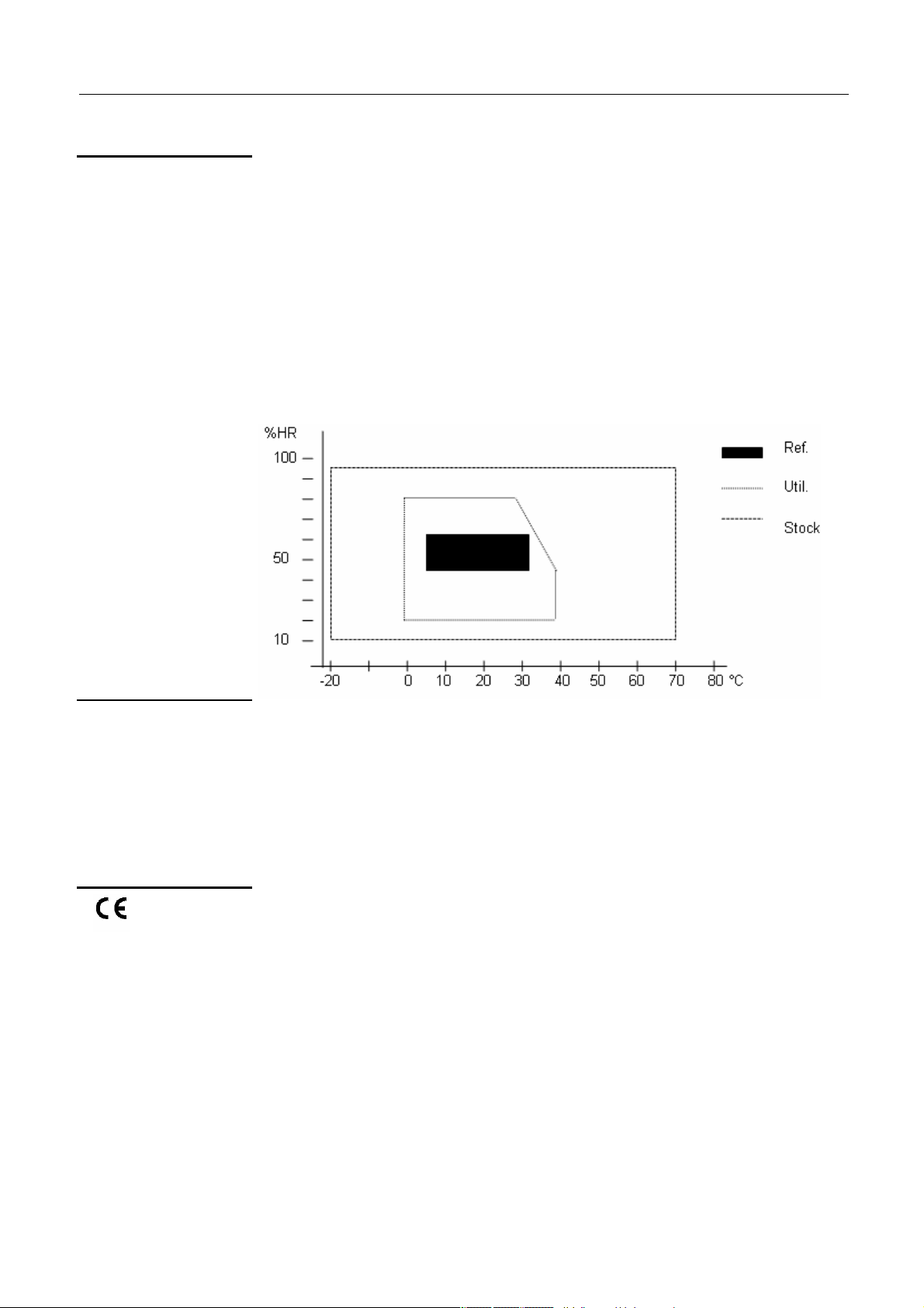
General Specifications
General Specifications
Environment
• Reference temperature 23° C ± 5° C 45 to 65 % RH
• Nominal usage range 5° C to 35° C 45 to 65 % RH
• Operating temperature 0° C to 40° C 20 to 80 % RH
• Storage temperature -20° C to + 70° C 10 to 95 % RH
• Use indoor
• Altitude < 2000 m
• Relative Humidity < 80 % up to 31° C
Power supply
Mains
Safety
CEM
• Voltage 120 V
• Frequency 50 - 60 Hz
• Consumption 20 VA max.
• Removable power supply cable
This device has been designed in compliance with the current CEM standards
and its compatibility has been tested in compliance with the following
standards:
Emission and Immunity: EN 61326-1 (2006)
Find Quality Products Online at: sales@GlobalTestSupply.com
XV - 60 Function Generators
www.GlobalTestSupply.com
Page 61

Mechanical Specifications
Mechanical Specifications
Mechanical
specifications
Box
Weight
Packaging
Size (support folded):
• length 190 mm
• width 227 mm
• height 130 mm
2.850 kg
330 x 260 x 200 mm
Find Quality Products Online at: sales@GlobalTestSupply.com
Function Generators XV - 61
www.GlobalTestSupply.com
Page 62

Supply
Supply
Delivered with the
instrument
Accessories
• Safety instructions
• Power supply cable
• USB A/B cable for programmable versions
• CD-ROM containing:
Operating instructions in 5 languages
Programming instructions in 2 languages
USB ‘CP210x USB to UART Bridge Controller’ USB Drivers
LabView and LabWindows Drivers
USBxPress application (USB port identification)
GX320E-Admin application (IP address application)
• USB
A/B cable ...............................................................................Cat. #2140.51
Find Quality Products Online at: sales@GlobalTestSupply.com
XVI - 62 Function Generators
www.GlobalTestSupply.com
 Loading...