

Page 1
AC Digital Signal Generator
Model DSG-8
User Manual
ENGLISH
1
Page 2

Copyright © Chauvin Arnoux®, Inc. d.b.a. AEMC® Instruments. All rights reserved.
No part of this documentation may be reproduced in any form or by any means (including electronic storage and retrieval or translation into any other
language) without prior agreement and written consent from Chauvin Arnoux
Chauvin Arnoux
15 Faraday Drive • Dover, NH 03820 USA
Tel: (800) 945-2362 or (603) 749-6434 • Fax: (603) 742-2346
This documentation is provided “as is,” without warranty of any kind, express, implied, or otherwise. Chauvin Arnoux
reasonable effort to ensure that this documentation is accurate; but does not warrant the accuracy or completeness of the text, graphics, or other
information contained in this documentation. Chauvin Arnoux
inconsequential; including (but not limited to) physical, emotional or monetary damages due to lost revenues or lost profits that may result from the
use of this documentation, whether or not the user of the documentation has been advised of the possibility of such damages.
Chauvin Arnoux
®
, Inc. d.b.a. AEMC® Instruments
®
, Inc. shall not be liable for any damages, special, indirect, incidental, or
®
, Inc. and AEMC® are registered trademarks of AEMC® Instruments.
®
, Inc., as governed by United States and International copyright laws.
®
, Inc. has made every
2
Page 3
Thank you for purchasing the
For best results from your simulator:
these operating instructions carefully
Read
Comply
with the precautions for use
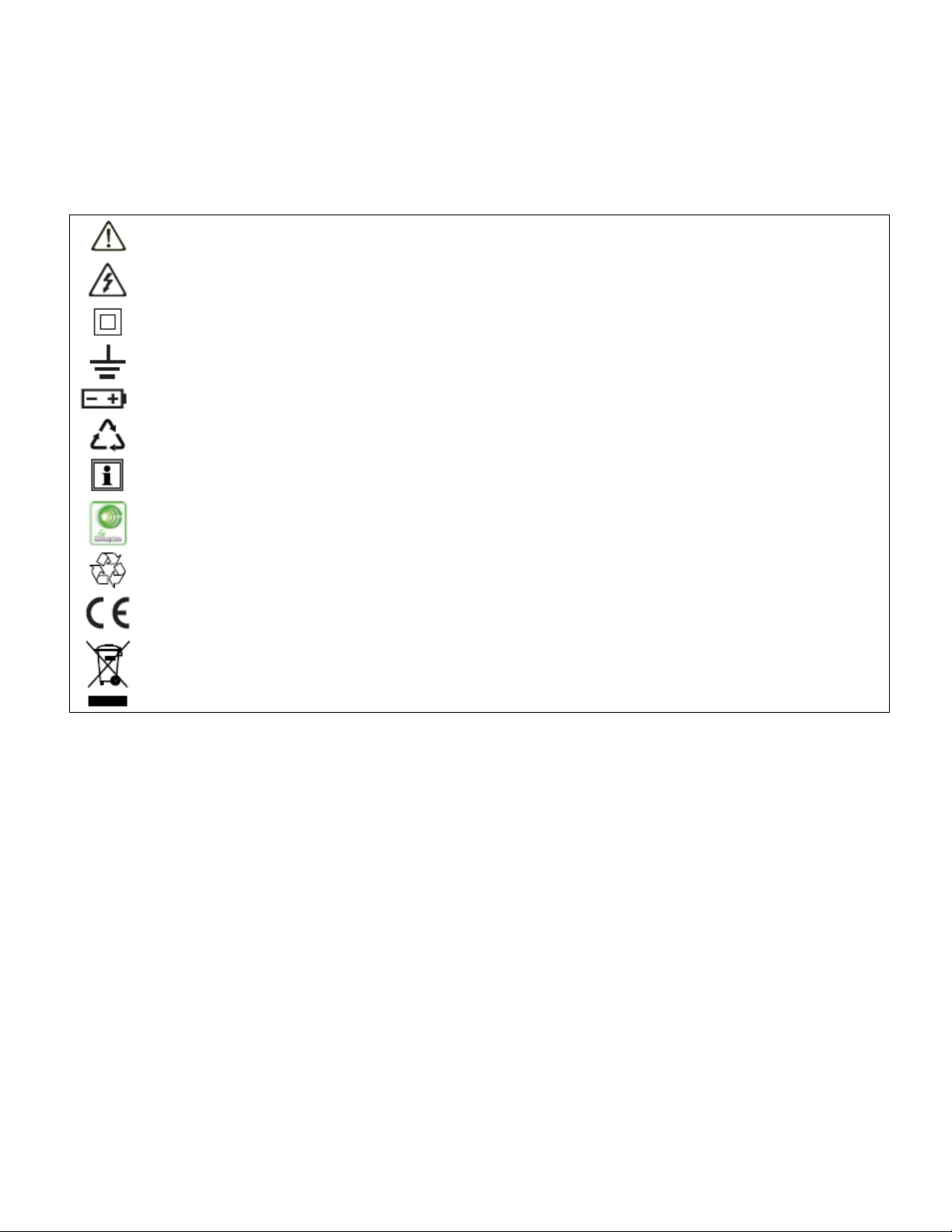
WARNING, risk of DANGER! The operator must refer to these instructions whenever this danger symbol
appears.
WARNING, risk of electric shock. The voltage applied to parts marked with this symbol may be
hazardous.
Equipment protected by double insulation.
Earth.
Battery.
The product is recyclable in accordance with standard ISO14040.
Information or useful tip.
AC Digital Signal Generator Model DSG-8.
This instrument exceeds regulatory requirements with respect to recycling and reuse.
Indicates conformity with European direc ti ves, in part ic ular LVD and EMC.
Indicates that, in the European Union, the instrument must undergo selective disposal in compliance
with Directive WEEE 2002/96/EC. This instrument must not be treated as household waste.
Definition of measurement categor ies:
CAT IV
Example: power feeders and protection devices.
CAT III
Example: distribution panel, circuit-breakers, machines or fixed industrial devices.
CAT II
Example: power supply to electro-domestic devices and portable tools.
corresponds to measurements taken at the source of low-voltage installations.
corresponds to measurements on building installations.
corresponds to measurements taken on circuits directly connected to low-volta ge ins ta llat ions .
3
Page 4

PRECAUTIONS FOR USE
Failure to observe the following safety instructions may result in electric shock, fire, explosion, and damage to the DSG8 and installation.
Carefully read and understand all precautions for use.
Be aware of all electrical hazards when using this instrument.
Using this instrument other than as specified may compromise its user protection features.
The safety of any system in which this instrument is incorporated is the responsibility of the integrator of the
system.
Do not use the instrument if it appears damaged, incomplete, or poorly closed.
Before each us e, ch eck the condi tion of the i nsulati on on the le ads, h ousing, and accessor ies. Any par t on which
the insulation is deteriorated (even partially) must be set aside for repair or scrapping.
Using the instrument without its battery compartment cover may result in electric shock to the user.
Before using your instrument, ensure it is completely dry.
When handling the leads, keep your fingers behind the physical guards.
Before removing the battery compartment cover, ensure all measurement leads and accessories are
disconnected. Replace all batteries at once.
Use personal protection equipment where appropriate.
All troubleshooting must be done by competent, accredited personnel.
4
Page 5

Contents
1. INTRODUCTION ........................................................................................................................................... 6
1.1 Receiving Your Shipment ......................................................................................................................... 6
1.2 Description ............................................................................................................................................... 7
1.3 Front Panel .............................................................................................................................................. 7
1.4 Output Leads ........................................................................................................................................... 7
2. SIMULATOR SOFTWARE ............................................................................................................................. 8
2.1 Installing the Simulator Software .............................................................................................................. 8
2.2 Simulator Software Interface .................................................................................................................. 10
2.3 Configuring a Simulation ........................................................................................................................ 11
2.3.1 Modifying a Preset ........................................................................................................................... 11
2.3.2 Creating a New Simulation .............................................................................................................. 13
3. OPERATION ............................................................................................................................................... 14
3.1 Front Panel Opera tion ............................................................................................................................ 14
3.2 Simulator Software Operation ................................................................................................................ 15
4. SPECIFICATIONS ....................................................................................................................................... 16
Repair .............................................................................................................................................................. 19
Limited Warranty ............................................................................................................................................. 20
Warranty Repairs ......................................................................................................................................... 20
5
Page 6
1. INTRODUCTION
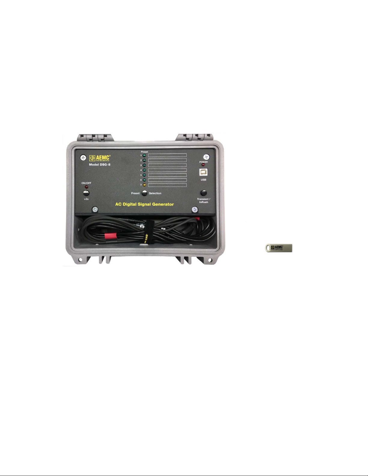
USB Thumb Drive with
1.1 Receiving Your Shipment
Upon receiving your product package, ensure the contents are consistent with the packing list. Notify your distributor of
any missing items. If the equipment appears to be damaged, file a claim immediately with the carrier and notify your
distributor at once, providing a detailed description. Save the damaged packing container to substantiate your claim.
Ordering Information:
AC Digital Signal Generator Model DSG-8…………………………………………………………………………….#6000.09
AC Digital Signal Generator Model DSG-8
Simulator Software and User Manual
(Not shown)
C-cell alkaline batteries (3)
Type A to Type B USB cable (#2140.46)
6
Page 7
1.2 Description
The AC Digital Signal Generator Model DSG-8 simulates waveforms for AEMC PowerPad, PowerPad III, and PEL
series instruments. The DSG-8 can create simulations for any AC distribution system supported by these instruments,
including capturing transients, inrush, and alarm events.
The simulator ships with seven preset simulations. These can be modified through the Simulator Software that comes
with the product. You can also create, save, and load new waveform s imulations with the Simulator Software (see §2).
Presets can be selected from either a computer running the Simulator Software or through the DSG-8 front panel. In
addition, custom simulations can be configured via the Simulator Software.
The DSG-8 is powered by USB or three C-cell alkaline batteries.
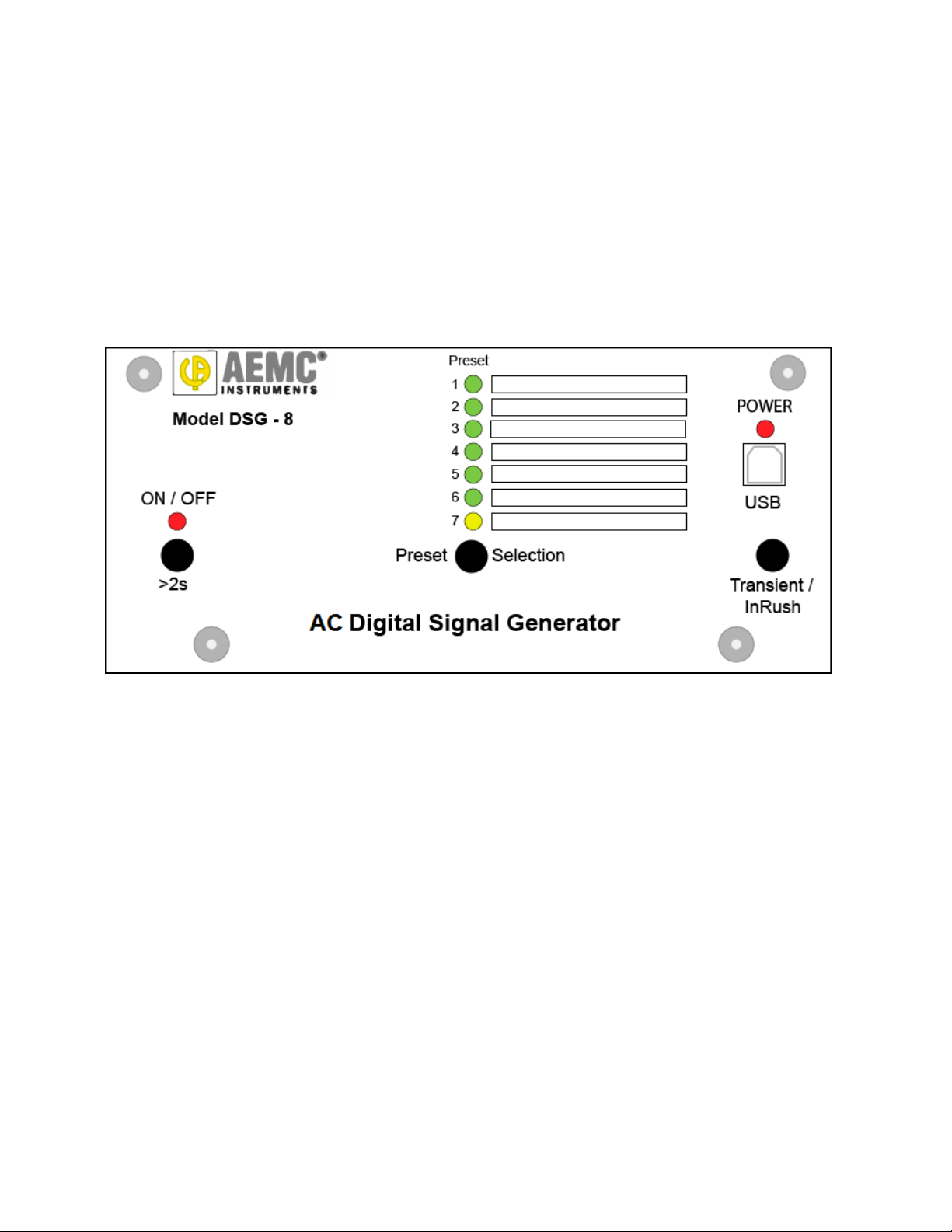
1.3 Front Panel
• Preset indicators identify which preset configuration (if any) is currently selected. The first six LEDs are green
when selected. The seventh (used for inrush simulations) is yellow. To the right of the indicators are spaces
onto which you can place labels (supplied with the product package) to identify each preset.
• Preset Selection button changes the preset. Holding the button down cycles through the seven preset options.
• POWER indicator glows red when the DSG-8 is running on USB power.
• USB Type B connection for connecting the simulator to a computer via a USB cable. The connection can also
be used to power the simulator from the computer or another USB power source.
• Transient/InRush button simulates a transient (when preset 1 through 6 or a user-created simulation is
selected) or inrush (when preset 7 is selected) on the connected instrument. The transient will run for as long as
this button is pressed; the inrush will run for the duration of its preconfigured setting.
• ON/OFF button when pressed for longer than two seconds powers the simulator ON and OFF. The associated
LED glows steady red when power is ON, and blinks when battery power is low (3.7V or below). When running
on battery power, the DSG-8 automatically turns OFF after 2 hours without user activity.
1.4 Output Leads
The DSG-8 includes four current and five voltage 18” (45.7cm) captive output leads. Current outputs attach to the power
instrument via AEMC/C.A-style connectors. Probe outputs are configured as SR193 probes. Each lead is labeled to
indicate the instrument terminal to which it should be connected.
7
Page 8

2. SIMULATOR SOFTWARE
The Simulator Software is used for setting up and running the DSG-8. The software enables you to:
• Connect to the DSG-8
• Manipulate the waveform by adding harmonics to any of the individual channels
• Define the amplitude of a waveform
• Set a secondary waveform for simulating a transient event
• Modify preset waveforms
• Create and save new waveforms
• Start a simulation
The Simulator Software allows you to create waveforms for many types of AC distributions systems. With both the
Simulator Software and DataView running on your computer, you can configure and start a simulation, and then view
real-time data from the instrument to see the results of the simulation.
Although it is possible to operate the DSG-8 from the simulator’s front panel; the Simulator Software provides additional
features, shown in the following table:
Simulator Software Front Panel
Presets
Transients/Trigger
Frequency
Save/Load
In addition, the Simulator Software displays a graphic representation of the waveform as defined by the currently
specified settings.
• Modify and save preset settings, including
Normal and Transient/InRush waveforms.
• Run a simulation with no preset selected.
• Set duration with single-cycle accuracy.
• Add a single-cycle subcycle transient.
Set specific frequency. Use predefined frequency.
Save a modified preset to the computer, or
load a previously saved preset.
• Use predefined presets.
• Must have a preset selected.
Duration defined by how long the
Transient/InRush button is pressed.
N/A
2.1 Installing the Simulator Software
The Simulator Software comes on the USB thumb drive that ships with the DSG-8. To load and run the software:
1. Insert the thumb drive in an available USB drive on your computer.
2. Open the Windows directory and go to the USB drive folder.
3. Locate the file setup.exe and click it. This opens the Simulator Software Installation Setup screen.
8
Page 9

4. Select the language for the Simulator Software interface.
5. In the Options field, select the DSG software, then click Install. Depending on your operating system you may
be prompted to confirm that you want to allow the setup program to make changes on your computer. If so, click
Yes.
6. The DSG InstallShield Wizard appears.
7. Click Next, then click Install. A status bar appears indicating the progress of the installation. When this is
complete, a screen appears indicati ng insta ll ati on is suc ces s f ul.
8. Click Finish to return to the Setup screen. You can now install Adobe Reader and/or the DSG-8 User Manual. (If
your computer does not include a program for reading .pdf files, you will need Adobe Reader to view the User
Manual online.) When you are finished, click Exit to leave the Setup screen.
9
Page 10

9. Connect the DSG-8 to your computer using the USB cable. The first time you do this, the communication driver
will install. A message appears when driver installation is complete.
10. Click the Simulator Software icon on your desktop to open the Simulator Software interface.
11. In the Simulator Software screen, ensure that the name of the DSG-8 appears in the Port field in the upper left
corner. If not, click Refresh. If the name still does not appear, check the USB connections between the
simulator and computer.
12. To ensure the Simulator Software is communicating with the DSG-8, change the setting in the Preset radio
button field. The Preset Selection LED for the selected preset should light up on the DSG-8 front panel.
2.2 Simulator Software Interface
• Port displays the name of the DSG-8 simulator. This indicates the simulator is ready to communicate with the
Simulator Software.
• Preset is a radio button field for selecting one of the seven available presets, or for selecting None. When you
select a preset, the waveform it defines automatically starts running on the DSG-8. To simulate an inrush event
(as opposed to a transient) select preset 7 – Inrush. To modify a preset’s settings, select it and make the
changes (see §2.3.1). Then click the Write Waveforms button. If you select None and then click Write
Waveforms, the currently selected settings will run on the simulator. Note that when None is selected, all Preset
LEDs on the simulator are OFF. To save these settings in a new simulation file, click Save (see be lo w).
• Normal Waveform Amplitude and Phase enables you to define harmonics for each available channel. This
section consists of two fields. Full scale sets the amplitude of the fundamental waveform, in terms of percentage
of the full fundamental. This can be from 1% to the default of 100%. The second field is a table of all available
channels. You can set up to 50 harmonics settings (including fundamental) for each channel (see §2.3).
Settings with non-zero values appear in bold.
• Phase Angles defines the phase angles between the voltage and current channels (V1 to VN, V1 to V2, and so
on). As you enter each setting, the defined waveform is displayed, with colors representing the channels (black:
V1 and I1, red: V2 and I2, blue: V3 and I3, green: VN and IN). To the right of the displayed waveform are
checkboxes for selecting channels.
10
Page 11

• Transient Duration sets the duration (in cycles) of the simulated transient. Use this field to define the duration
of the transient more precisely than is possible by pressing the Transient/InRush button on the DSG-8.
Allowable values are 1 through 65536. To define a transient shorter than one cycle, press the Subcycle button
(see below).
• Trigger initiates a transient or (when preset 7 is selected) inrush event.
• Transient Waveform Amplitude and Phase is similar to Normal Waveform Amplitude and Phase. It sets
amplitude (80% by default), harmonics, and phase angles for the simulated transient or inrush event.
• Transient Phase Angles is similar to Phase Angles. It includes the Subcycle button, which displays a dialog
for adding transients with durations shorter than one cycle of the main transient waveform.
• Frequency sets the frequency for the simulation. Allowable values are 45 through 65Hz.
• Save saves the current settings to a file on the computer. When you click this button, the Windows Save As
dialog box appears.
• Load loads a previously saved simulation file. When you click this button, the Open dialog box appears for
finding and selecting the desired simulation.
2.3 Configuring a Simulation
This section describes setting up a simulation. As explained in §2.2, you can create a new simulation, or modify an
existing one including any of the seven presets.
When configuring a simulation, ensure that th e wavef o rm amplitudes displayed in the Simulator Soft ware
interface do not exceed the display window. Also ensure that you enter realistic amplitude values for
harmonics and the fundamental. Otherwise the simulated waveforms could become distorted.
2.3.1 Modifying a Preset
1. With the Simulator Software running, click the preset you want to change in the Preset field (1 through 6 for
transient simulations, 7 for inrush simulation).
2. In the Normal Waveform Amplitude and Phase section, set the Full scale field.
3. Select a harmonic listed in the table and double-click it. This displays the Harmonic Amplitude and Phase dialog
box.
4. Enter the amplitude (in percent) and phase of the harmonic for each channel, then click OK. A color-coded
graphic showing the Normal waveform appears.
11
Page 12

5. In the Phase Angles section, select the phase angles between the channels. As you make selections the
waveform displayed to the right of this section automatically updates. You can choose which channels to
include in the displayed waveform by selecting/deselecting the check boxes to the right. (These selections do
not affect the Phase Angles settings.)
6. In the Transient Waveform Amplitude and Phase section, set the values for a simulated transient/inrush ev e nt.
The transient waveform appears in the display window to the right.
7. In the Frequency field, specify the desired frequency for the simulation.
8. If you are modifying preset 7 (inrush), skip the remainder of this step and go to step 9 below. If you are
modifying a transient preset (presets 1 through 6), enter the duration of the transient in the Transient field. Then
complete the Transient Phase Angles fields. To add a subcycle transient to the transient waveform, click
Subcycle. This displays the Subcycle Transient dialog box.
This dialog box enables you to add a transient with a duration shorter than one cycle of the transient
waveform. Select the channel(s) on which the transient will appear by checking/unchecking the desired check
boxes on the right. Then complete the remaining fields:
• Frequency is the transient frequency. This must be greater than the transient wav ef orm’s frequency
(step 7).
• Amplitude defines the amplitude of the transient as a percentage of the transient waveform’s full-scale
value. For example, to define a transient with an amplitude 50% the transient waveform, enter 50.0.
• Duration is the number of cycles (defined by the Frequency field above) the transient will last.
• Delay defines when the transient begins, in terms of the transient’s frequency. For example, in the
preceding illustration the Frequency is set to 1000Hz. This results in 16.67 transient cycles over a
single transient wavefor m’s 60Hz cycle. With Duration set to 1 cycle and Delay set to 7 cycles, a single
transient cycle appears on the transient waveform, 7 transient cycles after the beginning of the
waveform.
• Decay enables you to gradually reduce the transient’s amplitude with each cycle. For example, if the
transient Duration is 10 cycles and the Decay is 10 cycles, the transient will begin with the full
amplitude defined in the Amplitude field, and then incrementally decay to zero by the end of the 10cycle transient.
The Decay and Delay values can be used together to create a “ringing” effect by adding more cycles
and “decaying” these cycles starting at the Delay point. You can also create a half-cycle bump or dip
by setting Duration to 0.5 and Delay to a whole number (for a bump) or a number that ends in .5 (for a
dip).
After you complete these fields, press OK.
12
Page 13

9. Click Write Waveform. The modified preset is saved in the DSG-8. The instrument also displays the updated
waveform.
10. To reset the preset back to its original settings, click Load. Then select the desired preset file. When the preset
is displayed in the Simulator Software, click Write Waveforms to save it in the simulator.
2.3.2 Creating a New Simulation
1. With the Simulator Software running, click None in the Preset field.
2. In the Normal Waveform Amplitude and Phase section, set the Full scale field.
3. Select a harmonic listed in the table and double-click it. This displays the Harmonic Amplitude and Phase dialog
box.
4. Enter the amplitude (in percent) and phase of the harmonic for each channel, then click OK.
5. In the Phase Angles section, select the phase angles between the channels. As you make selections the
waveform displayed to the right of this section automatically updates.
6. Choose which channels to include in the displayed waveform by selecting/deselecting the check boxes to the
right of the displayed waveform.
7. In the Frequency field, select the desired frequency for the simulation.
8. In the Transient Waveform Amplitude and Phase section, set the values for a simulated transient event.
9. In the Transient Phase Angles section, select the phase angles between the channels. As you make selections
the waveform displayed to the right of this section automatically updates.
10. To add a subcycle transient to the transient waveform, click Subcycle. Then complete the Subcycle Transient
dialog box.
11. Enter the duration of the transient in the Transient field.
12. To run the simulation on the DSG-8, click Write Waveform. (Note that this does not save the simulation.)
13. To save the simulation, click Save to display the Save As dialog box. This lets you enter a name and location
for the simulation file, which by default includes the extension .ini.
14. To modify a previously saved simulation, click Load and select the simulation. Then change its settings as
instructed above, and save it under its original name (or different name to create a new file).
13
Page 14

3. OPERATION
As a safety feature, the DSG-8 output voltage is limited to 55V
To simulate a higher voltage, you must set the scaling on your power instrument as instructed b y its User
Manual. For example, to simulate a 110V input, set the scaling on your instrument to 2:1.
You can operate the DSG-8 from its front panel interface, or through the Simulator Software. You must use the
Simulator Software to do the following:
• Run a simulation other than one of the seven presets.
• Run a transient with single-cycle duration precision.
In addition, all simulation configuration (other than selecting a preset) must be performed through the Simulator
Software (see §2).
Before beginning operati on , connec t the DSG -8 output leads to the instrument. Each lead is labeled to indicate the
instrument terminal to which it should be connected.
(Earth/Ground to phase 1, 2, 3 and neutral).
RMS
3.1 Front Panel Operation
1. If you plan to run the simulator on USB power, plug in the USB cable.
2. Press the ON/OFF button for longer than two seconds. (The ON/OFF indicator will light up.)
3. Press and hold the Preset Selection button until the desired preset LED lights up. Available default presets are
as follows:
1 (Clean split-phase)
2 (Clean three-phase (Load) 80% transient)
3 (Clean three-phase (Source) 80% transient)
4 (Three-phase 10% harmonic 3 (Load) 30% harmonic 3)
5 (Three-phase 10% harmonic 3 through 11 (Load))
6 (Three-phase 10% harmonics 2 through 10 (Load))
7 (Three-phase 20% current amplitude (load): inrush waveform at 80%) used for inrush simulation
If this simulation will include a transient event, select one of the first six presets. If it includes an inrush event,
select preset 7. Note that these presets can be modified via the Simulator Software (see §2). The simulation
begins immediately when the preset is selected.
4. To simulate a transient or inrush event, press the Transient/InRush button. Transients will run for as long as the
button is pressed; inrush events will run for the predefined duration.
When the simulation is running, the simulated measurements appear in the real-time display on the instrument’s LCD. If
the instrument is connected to DataView, you can also view the simulation in the Real-Time Data frame in the
instrument’s Control Panel.
If the DSG-8 is running on battery power, it turns OFF after two hours without user activity. To run a simulation
for longer than two hours unattended, run the simulator on USB power.
14
Page 15

3.2 Simulator Software Operation
1. Using the USB cable provided with the product package, connect the DSG-8 to the computer. Then press the
ON/OFF button for longer than two seconds. (The ON/OFF indicator will light up.)
2. Launch the Simulator Software, if it is not already running.
3. Confirm the DSG-8 is connected by ensuring its name appears in the Port field (see §2.1).
4. In the Preset field, select one of the following:
None (the simulation will be defined by the currently displayed settings, or you will load a previous ly saved
simulation)
1 (Clean split-phase)
2 (Clean three-phase (Load) 80% transient)
3 (Clean three-phase (Source) 80% transient)
4 (Three-phase 10% harmonic 3 (Load) 30% harmonic 3)
5 (Three-phase 10% harmonic 3 through 11i (Load))
6 (Three-phase 10% harmonics 2 through 10 (Load))
7 (Three-phase 20% current amplitude (load): inrush waveform at 80%) used for inrush simulation
Note that presets can be modified. If this simulation will include an inrush event, select preset 7.
To run a simulation you have previously created and saved, select None. Then press the Load button and
select the desired simulation file.
The simulation begins immediately when a preset is selected.
5. To change a simulation, edit the settings as instructed by §2.2. Then press Write Waveforms to write the new
settings to the DSG-8. Note that doing this while a preset other than None is selected will save these setting in
the DSG-8, overwriting the previous preset values .
6. To simulate a transient enter the duration (in cycles) in the Transient field. Then click Trigger to initiate the
transient simulation.
7. To simulate an inrush, select preset 7. Then click Trigger.
When the simulation is running, the simulated measurements appear in the real-time display on the instrument’s LCD. If
the instrument is connected to DataView, you can also view the simulation in the Real-Time Data frame in the
instrument’s Control Panel.
15
Page 16

4. SPECIFICATIONS
Channels
Eight
Output Termination
Five 4mm safety banana connectors
Output Voltage
0 to 55V
(Earth/Ground to phase 1, 2, 3 and neutral)
Accuracy
Unspecified (see graphs below)
Frequency Range
45 to 65Hz
Sample Rate
128 samples/cycle
Harmonics
Programmable harmonic content to the 50th harmonic
Inrush
14 cycle inrush simulation
Presets
Seven preset waveforms (six normal/transient, one normal/inrush)
Communication
USB 2.0
Power Consumption
70mA at max output all eight channels
Power Source
USB 5V
Battery Life
100 hours active mode (output ON)
Reference conditions: 73.4° ± 5.4°F (23°C ± 3°C), 30 to 50% RH, 50/60Hz, b attery voltage 4.5V ± 10%.
Four AEMC/C.A connector
RMS
0 to 1V
AEMC/C.A connector
RMS
Three 1.5V C-cell alkaline batteries
60 days sleep mode (output OFF)
16
Page 17

Typical Harmonic Accurac y
17
Page 18

Typical Accuracy vs Amplitude of Fundamental
18
Page 19

Repair
For instrument repair:
You must contact our Service Center for a Customer Service Authorization Number (CSA#). This will ensure that when
your instrument arrives, it will be tracked and processed promptly. Please write the CSA# on the outside of the shipping
container.
Ship To:
Chauvin Arnoux
15 Faraday Drive • Dover, NH 03820 USA
Phone: (800) 945-2362 (Ext. 360)
(603) 749-6434 (Ext. 360)
Fax: (603) 742-2346 or (603) 749-6309
E-mail: repair@aemc.com
(Or contact your authorized distributor.)
Costs for repair are avai la bl e.
NOTE: You must obtain a CSA# before returning any instrument.
Technical and Sales Assistance
If you are experiencing any technical problems, or require any assistance with the proper operation or application of
your instrument, please call, fax, or e-mail our technical support team:
Chauvin Arnoux
Phone: (800) 343-1391 • (508) 698-2115
Fax: (508) 698-2118
E-mail: techsupport@aemc.com
®
, Inc. d.b.a. AEMC® Instruments
®
, Inc. d.b.a. AEMC® Instruments
19
Page 20

Limited Warranty
The DSG-8 is warranted to the owner for a period of two years from the date of original purchase against defects in
manufacture. This limited warr ant y is given b y AEMC
This warranty is void if the instrument has been tampered with or abused, or if the defect is related to service not
performed by AEMC
®
Instruments.
Full warranty coverage and product registration is available on our website at: www.aemc.com/warranty.html
Please print the online Warranty Coverage Information for your records.
What AEMC
®
Instruments will do:
If a malfunction occurs within the two-year period , you may return the instrument to us for repair, provided we have your
warranty registration information on file or a proof of purchase. AEMC
the faulty material.
Warranty Repairs
What you must do to return an instrument for Warranty Repair:
First, request a Customer Service Authorization Number (CSA#) by phone or by fax from our Service Department (see
address below), then return the instrument along with the signed CSA Form. Please write the CSA# on the outside of
the shipping container. Return the instrument, postage or shipment pre-paid to:
Ship To:
Chauvin Arnoux
15 Faraday Drive • Dover, NH 03820 USA
Phone: (800) 945-2362 (Ext. 360)
(603) 749-6434 (Ext. 360)
Fax: (603) 742-2346 or (603) 749-6309
E-mail: repair@aemc.com
Caution: To protect yourself against in-transit loss, we recommend you insure your returned material.
NOTE: You must obtain a CSA# before returning any instrument.
®
, Inc. d.b.a. AEMC® Instruments
®
Instruments, not by the distributor from whom it was purchased.
.
®
Instruments will, at its option, repair or replace
20
Page 21

99-MAN 100437 V3
03/17
Chauvin Arnoux
®
, Inc. d.b.a. AEMC® Instruments
15 Faraday Drive • Dover, NH 03820 USA • Phone: (603) 749-6434 • Fax: (603) 742-2346
www.aemc.com
21
 Loading...