

Page 1
QUICK START
USER GUIDE
8335
PowerPad
®
IMPORTANT WARRANTY NOTE:
By registering online within 30 days from the date of
purchase, your warranty will be extended to 3 years
Page 2

Statement of Compliance
Chauvin Arnoux®, Inc. d.b.a. AEMC® Instruments
certifies that this instrument has been calibrated
using standards and instruments traceable to
international standards.
We guarantee that at the time of shipping your
instrument has met its published specifications.
An NIST traceable certificate may be
requested at the time of purchase, or obtained
by returning the instrument to our repair and
calibration facility, for a nominal charge.
The recommended calibration interval for this
instrument is 12 months and begins on the date of
receipt by the customer. For recalibration, please
use our calibration services. Refer to our repair
and calibration section at www.aemc.com.
Serial #: ________________________________
Catalog #: ______________________________
Model #: 8335
Please fill in the appropriate date as indicated:
Date Received: _________________________________
Date Calibration Due:
_______________________
Chauvin Arnoux®, Inc.
d.b.a AEMC® Instruments
www.aemc.com
Page 3
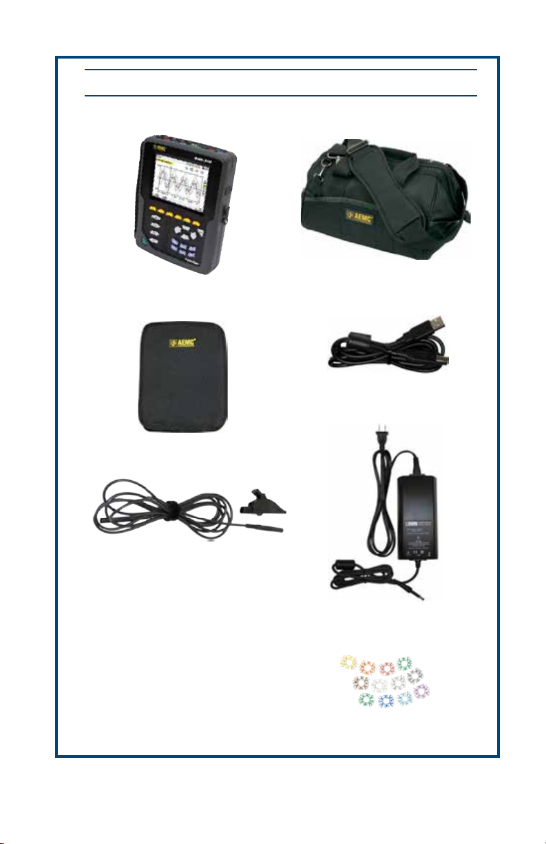
Shipping Contents:
(1) PowerPad® Model 8335
Cat. #2136.20
(1) Soft Carrying Pouch
Cat. #2140.15
PRODUCT PACKAGING
(1) Large Classic Tool Bag
Cat. #2133.73
(1) 5 ft USB Cable
Cat. #2140.46
(5) Black Test Leads and Alligator Clips
Also Included:
4 GB USB Stick (DataView/User Manual)
NiMh Battery - installed
Kits will also include (order dependent):
(4) MN93-BK current probes
(4) MN193-BK current probes
(4) SR193-BK current probes
(4) AmpFlex® 193-24-BK (24") current sensors
(4) AmpFlex® 193-36-BK (36") current sensors
(4) MR193-BK current probes
(4) MiniFlex® MA193-10-BK current sensors
(3) AmpFlex® 193-24-BK and (1) MN193-BK
Cat. #2140.43
(1) Power Adapter 110/240V w/ Power Cord
Cat. #5000.19
(12) ID Markers
Cat. #2140.45
USB STICK: DataView® software and complete user manual for the Model 8335
can be located on the USB stick supplied with the instrument.
Page 4
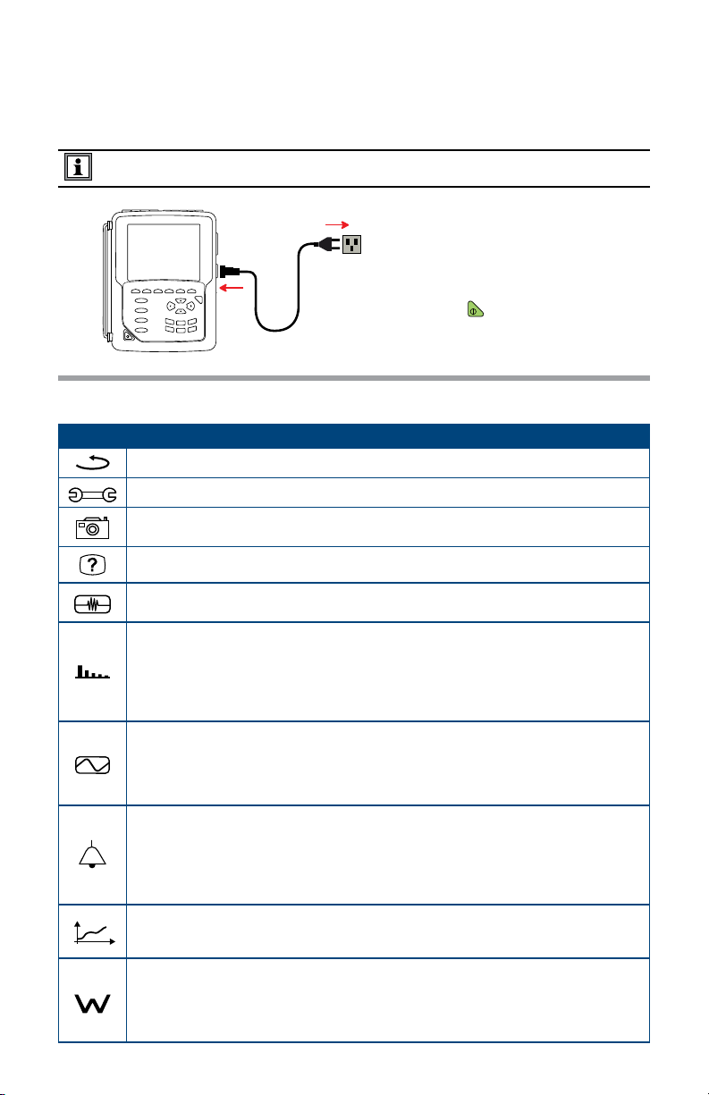
Charging the Battery
Fully charge the battery before the first use.
The batteries automatically begin recharging when the instrument is connected to AC power.
Only use the supplied AC power adapter to recharge the batteries.
NOTE: A full recharge of a completely discharged battery takes 5 hours approx.
120V ± 10%, 60Hz
230V ± 10%, 50Hz
Button Functions
BUTTON DESCRIPTION
Return to the choice of measurement view.
Configure the PowerPad® (SET-UP).
Take a snapshot of the current screen or access screens already stored in the memory.
Record associated waveform and power measurement data.
Get help on the current display functions, in the language chosen by the user.
Transients or Inrush Current:
• Sets and views transient and inrush current waveforms associated with rapid changes in input
Harmonics Mode:
• Displays the harmonics in percent and value ratios for voltage, current and power for each
harmonic through the 50th
• Determines harmonic current produced by non-linear loads
• Analyzes the problems caused by harmonics according to their order
(heating of neutrals, conductors, motors, etc)
Waveforms Mode:
• Displays voltage and current waveforms or vector representation
• Identifies signal distortion signatures
• Displays of amplitude and phase unbalance for voltage and current
• Checks connections for correct phase order
Alarm Events:
• Provides a list of the alarms recorded according to the thresholds programmed during
configuration
• Logs interruption with half-cycle resolution
• Determines energy consumption exceedances
• Stores value, duration, date, time and set point for up to 4096 events
Trend Mode:
• Lists all recording trends and views them on the display
(Urms, Vrms, Arms, etc)
Power / Energy:
• Displays power levels and the associated parameters (power factor, displacement and tangent)
• Energy monitoring
• Four quadrant measurement to discern produced/consumed active energies and inductive/capacitive reactive energies
To recharge the battery:
• Connect the supplied power
cord to the instrument and AC
power.
• The
button lights and will
go out when the power cord is
disconnected.
Page 5

Control Features
1
2
6
7
8
3
4
?
5
1. Over molded protective housing
2. LCD Display
3. Six function buttons (yellow)
4. Four function buttons (see chart, left)
5. ON/OFF button
6. Four current inputs and five voltage
inputs
Connection Terminals
1
®
PowerPad
7. USB port
8. Input for external power supply
and battery charging
9. Confirm/Enter button
10. Navigation buttons
11. Six mode buttons (see chart, left)
2
9
10
11
3
1. Four (4) current inputs on the top of
the instrument to enable the use of
current sensors (MN, SR, AmpFlex®,
MiniFlex®, and MR probes).
2. Five (5) voltage inputs.
3. Insertion locations for the current and
voltage color-coded ID markers
Page 6

Instrument Configuration
NOTE: The instrument configurations can also be modified through the DataView® software.
NOTE: The instrument must be configured the first time it is used. The configuration is
saved in memory when the instrument is turned OFF.
Press the
button to configure the unit. The following sub-menus appear:
• Set the display language by pressing the yellow button corresponding to the screen
language icons.
• The parameter that is ready to be configured will be highlighted in yellow. To move to a
different parameter, use the ▲ and ▼ buttons.
• Press the Enter
button to select a parameter.
• Use the ◄ and ► buttons to change a value or setting.
• When finished, return to the Configuration menu by pressing the
button.
PARAMETER FUNCTION
Date / Time
Display
Calculation Methods
Electrical Connection
Sensors & Ratios
Transient Mode
Trend (Recording) Mode
Alarm Mode
Erase Memory
About
Sets the date and time format
Adjusts the contrast and brightness of the display;
Defines the color of the voltage and current curves
Determines if harmonics are used or not used in calculations of reactive quantities
(power and energy)
• With harmonics: Harmonics are taken into account when calculating reactive
parameters.
• Without harmonics: Only the fundamental part is used for the calculation of
reactive parameters
Determines the type of connection to the network
• Single-Phase
• Split-Phase
• 3-Phase 4-Wire
• 3-Phase 5-Wire
Defines the type of current probe to connect
• MN93: 200A
• MN193: 100A or 5A (with variable ratio)
• SR193: 1000A
• SL261: 10A and 100A range
• AmpFlex
• MiniFlex
• MR193: 1000A
• 5A three-phase adapter (3-channel only)
Configures the voltage and current thresholds
Selects the parameters to record (up to 4 configurations)
Defines the parameters of an alarm
Deletes configurations, alarm settings, snapshots and recordings
Displays the serial number, software and hardware version
®
Sensors: 3000A (measures up to 6500Arms)
®
Sensors: 1000A
AC/1200ADC
Page 7

Getting Started
NOTE: Make sure the PowerPad® is fully charged before use.
Connecting:
• Start the instrument by pressing the
• Configure the instrument to obtain the required results and type of network.
• Connect the current leads and sensors to the PowerPad®.
• Connect the ground and/or neutral lead to the network ground and/or neutral (when
distributed), as well as the corresponding current sensor.
• Connect the L1 phase lead to the network L1 phase, as well as the corresponding
current sensor.
• Repeat the procedure for phases L2, L3 and N.
Disconnecting:
• Proceed in the reverse order to connecting, always finishing by disconnecting the
ground and/or neutral (when distributed).
• Disconnect the leads and press the
• Recharge the battery, if necessary.
button.
button to turn the instrument off.
Installation of the Leads and Current Sensors
Twelve sets of color-coded rings and inserts are supplied with the PowerPad®. Use these ID
markers to identify the leads and input terminals.
• Detach the appropriate inserts from the color-coded marker and place them in the holes
provided under the terminals (larger inserts for current terminals, smaller inserts for voltage terminals).
• Clip the rings of the same color to the ends of the lead you will be connecting to the
terminal.
Page 8

Installing DataView
DO NOT CONNECT THE INSTRUMENT TO THE PC BEFORE INSTALLING THE
SOFTWARE AND DRIVERS.
1. Insert the USB stick into an available USB port (wait for driver to be installed).
2. If Autorun is enabled, an AutoPlay window should appear. If Autorun is disabled, it will be
necessary to open Windows Explorer, then locate and open the USB stick drive labeled
“DataView” to view the files on the drive.
3. In the AutoPlay window, select “Open folder to view files”.
4. Double-click on Setup.exe from the opened folder view to launch the Dataview® setup
program.
NOTE: For more information on using DataView®, refer to the Model 8335 user manual that is
supplied on the USB stick.
®
Updating Software & Firmware
To provide our customers the best possible service in terms of performance and technical upgrades,
AEMC® offers free software and firmware updates on our website.
• Visit us at: www.aemc.com
• Click on the Tech Info tab and choose the desired software or firmware download.
DataView® can also be updated by selecting “Update” from the Help menu within the software.
WARNING: Updating the firmware will erase all stored data in the instrument. It is
recommended to download all stored data before performing any firmware updates.
Page 9

Repair and Calibration
To ensure that your instrument meets factory specifications, we recommend that it
be scheduled back to our factory Service Center at one-year intervals for recalibration, or as required by other standards or internal procedures.
For instrument repair and calibration:
You must contact our Service Center for a Customer Service Authorization Number
(CSA#). This will ensure that when your instrument arrives, it will be tracked and
processed promptly. Please write the CSA# on the outside of the shipping container.
If the instrument is returned for calibration, we need to know if you want a standard
calibration, or a calibration traceable to N.I.S.T. (Includes calibration certificate plus
recorded calibration data).
Ship To: Chauvin Arnoux
15 Faraday Drive
Dover, NH 03820 USA
Phone: (800) 945-2362 (Ext. 360)
(603) 749-6434 (Ext. 360)
Fax: (603) 742-2346 or (603) 749-6309
E-mail: repair@aemc.com
(Or contact your authorized distributor)
Costs for repair, standard calibration, and calibration traceable to N.I.S.T. are
available.
NOTE: You must obtain a CSA# before returning any instrument.
®
, Inc. d.b.a. AEMC® Instruments
Technical and Sales Assistance
If you are experiencing any technical problems, or require any assistance with the
proper operation or application of your instrument, please call, mail, fax or e-mail
our technical support team:
Chauvin Arnoux®, Inc. d.b.a. AEMC® Instruments
200 Foxborough Boulevard
Foxborough, MA 02035 USA
Phone: (800) 343-1391
(508) 698-2115
Fax: (508) 698-2118
E-mail: techsupport@aemc.com
www.aemc.com
NOTE: Do not ship Instruments to our Foxborough, MA address.
Page 10

Limited Warranty
The Model 8335 is warranted to the owner for a period of one year from the date
of original purchase against defects in manufacture. This limited warranty is given
by AEMC® Instruments, not by the distributor from whom it was purchased. This
warranty is void if the unit has been tampered with, abused or if the defect is related
to service not performed by AEMC® Instruments.
Full warranty coverage and registration is available on our website:
www.aemc.com/warranty.html.
IMPORTANT WARRANTY NOTE:
By registering online within 30 days from the date of
purchase, your warranty will be extended to 3 years
Please print the online Warranty Coverage Information for your records.
What AEMC® Instruments will do:
If a malfunction occurs within the one-year period, you may return the instrument
to us for repair, provided we have your warranty registration information on file or
a proof of purchase. AEMC® Instruments will, at its option, repair or replace the
faulty material.
Warranty Repairs
What you must do to return an Instrument for Warranty Repair:
First, request a Customer Service Authorization Number (CSA#) by phone or by fax
from our Service Department (see address below), then return the instrument along
with the signed CSA Form. Please write the CSA# on the outside of the shipping
container. Return the instrument, postage or shipment pre-paid to:
Ship To: Chauvin Arnoux®, Inc. d.b.a. AEMC® Instruments
15 Faraday Drive
Dover, NH 03820 USA
Phone: (800) 945-2362 (Ext. 360)
(603) 749-6434 (Ext. 360)
Fax: (603) 742-2346 or (603) 749-6309
E-mail: repair@aemc.com
Caution: To protect yourself against in-transit loss, we recommend you insure your
returned material.
You must obtain a CSA# before returning any instrument.
Page 11

NOTES:
Page 12

10/13
99-MAN 100392 v2
Chauvin Arnoux
®
, Inc. d.b.a. AEMC® Instruments
15 Faraday Drive • Dover, NH 03820 USA • Phone: (603) 749-6434 • Fax: (603) 742-2346
www.aemc.com
 Loading...