

Page 1
TEST AND MEASUREMENT
(LAB) INSTRUMENTS
Page 2
TEST AND MEASUREMENT (LAB) INSTRUMENTS
DC POWER SUPPLIES
MODELS AX & AX
Rugged and accurate power supplies
can handle a direct short without
causing damage
SPECIFICATIONS
MODELS AX AX
Number of Outputs 2 3
VOLTAGE
Output 1 & 2 0 to 30VDC 0 to 30VDC
Output 3 (No display) – 2.7 to 5.5VDC
Display Resolution 100mV 100mV
Basic Accuracy ±0.5% of Reading ±1ct ±0.5% of Reading ±1ct
Residual Ripple ±1mVrms ±1mVrms
LINE REGULATION
±10% Line Voltage ±0.03% of Reading ±2mV
LOAD REGULATION
0 to 2.5A ±0.02% of Reading ±5mV
0 to 5A – ±0.2% Reading ±10mV
CURRENT
Output 1 & 2 0 to 2.5A 0 to 2.5A
Output 3 – 5A max (no adjustment)
Resolution 10mA 10mA
Basic Accuracy ±0.5% of Reading ±1ct ±0.5% of Reading ±1ct
Limit Indicator LED, Outputs 1 and 2 LED, Outputs 1, 2 and 3
Short-circuit Protection Electronic current limitation with voltage shutdown
Overheating Protection Thermal protection
OUTPUT COUPLING
Tracking
Series Mode 0 to 60V
Parallel Mode 0 to 30VDC/0 to 5A
Power Source 110V, 50/60Hz (220V optional)
Output 1: Master/Output 2:
Slave Proportional Slave Tracking
(0 to 100% of Master)
DC/0 to 2.5A
FEATURES
• Dual 0 to 30Vdc/0 to 2.5A outputs
• 5.5V/5A output (Model AX503)
• Series and parallel operation permit 0 to 60V
or 0 to 5A output
• Low noise (<1mV ripple) and stable linear
technology for clean output
• High efficiency toroidal transformers: no fan
and low electromagnetic emissions
• Active protection against overloads, short
circuits and overheating
• Unique variable tracking mode for master/
slave operation: slave or master track
proportionally to the original setting
• Simultaneous display of voltage and current
• Highly visible green (V) and red
(A) LED displays
CATALOG NO. DESCRIPTION
2130.06 DC Power Supply Model AX502 (110V, 60Hz, US Plug)
2130.07 DC Power Supply Model AX503 (110V, 60Hz, US Plug)
211 7.7 8
128
Lead – Set of 3, (2 Color-coded Safety Leads, 1 Ground Lead, 2 Color-coded Alligator Clips and
2 Color-coded Grip Probes) for Power Supply Models AX501-AX503
ACCESSORIES
Optional lead set includes two color-coded leads,
one ground lead (stripped), two alligator clips
and two grip probes. Catalog #2117.78
Page 3

TEST AND MEASUREMENT (LAB) INSTRUMENTS
IP
50
SPECIFICATIONS
TYPES Multiplying factor in
1 10
BR07 + + + + + + +
Accuracy
Max current
mADC
TYPE Multiplying factor in nF
BC05 + + + + +
Operating Temperature: 14° to 131°F (-10° to + 55°C)
Storage Temperature: -40° to 158°F (-40° to + 70°C)
Relative Humidity: 20% < RH < 96%
Altitude: 2000m
Dimensions - BC05: 12 x 3.4 x 3" (310 x 86 x 76mm)
Weight - BC05: 2.2 lbs (1kg)
Dimensions - BR07: 16 x 3.4 x 3" (410 x 86 x 76mm)
Weight - BR07: 3 lbs (1.4kg)
Watertightness
(as per EN 60529 Ed. 92):
Rated Voltage: 150V
1%
±10mΩ
700mA 200mA 70mA 20mA 7mA 1mA 0.1mA
1%
±10mΩ
0.1 1
Installation Category II - Pollution level 2
100
1%
±10mΩ
1k 10k 100k 1M
1%
±10mΩ
10
Protection index IP 40
1%
±10mΩ
100 1k
1%
±10mΩ
1%
±10mΩ
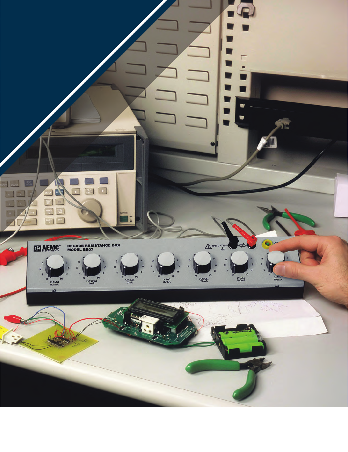
DECADE BOXES
MODELS BR & BC
Bench top decade boxes that
stand up to the task
FEATURES
RESISTANCE DECADE BOX MODEL BR
• Resistance box: 7 decades covering
a range from 1Ω to 11.11111MΩ
• 11-position switches
• Output on safety sockets Ø 4mm
• Accuracy: 1% ± 10mΩ on all ranges
CAPACITANCE DECADE BOX MODEL BC
• Capacitance box with 5 decades;
11 position switches
• Total capacitance 11.111µF
• Very high insulation
• Output on safety sockets Ø 4mm
• The residual capacitance is
approximately 25 pF
• Accuracy: 3% on all the ranges
(residual capacitance deducted)
CATALOG NO. DESCRIPTION
2131.25 Resistance Decade Box Model BR07 (x1Ω, x10Ω, x100Ω, x1kΩ, x10kΩ, x100kΩ, x1MΩ, 1%)
2131.26 Capacitance Decade Box Model BC05 (x0, 1nF, x1nF, x10nF, x100nF, x1knF, 3%)
2131.35 Lead – Replacement, 6ft Safety Lead, 4mm Female to Female for use with Decade Boxes
129
Page 4

TEST AND MEASUREMENT (LAB) INSTRUMENTS
MULTIFUNCTION INSTALLATION TESTERS
MODELS C.A N & C.A
Safety for your electrical
installations and high
performance with these
unique instruments
SPECIFICATIONS
MODELS C.A N C.A
CONTINUITY / RESISTANCE
I Rated/Range/Resolution
Range/Resolution/Accuracy 4kΩ/1Ω/±(1.5% of measurement + 5cts) 40 to 400kΩ/10 to 100Ω/±(1.5% of measurement + 2cts)
INSULATION
Rated Voltage 50/100/250/500/1000Vdc
Range/Resolution/Accuracy 0.01MΩ to 2GΩ/10kΩ to 1MΩ/±(5% of measurement + 3cts)
Short-Circuit Current ≤ 3mA
GROUND RESISTANCE
3-Point
Range/Resolution/Accuracy
Ufk Complies with SEV 3569
1-Point Selective
Range/Resolution/Accuracy 0.20 to 39.99Ω – 40 to 399.9Ω/0.01 to 0.1Ω/±(10% of measurement + 10cts) (ISel via clamp)
0.50 to 40Ω/0.01Ω/±(2% of measurement + 10cts) 40Ω to 15kΩ/0.1 to 1Ω/±(2% of measurement + 2cts)
LOOP IMPEDANCE ZS LPE & ZI LN OR LL / POINT LIVE GROUND
Live Ground
Installation Voltage/Frequency 90 to 500V/15.8 to 17.5Hz – 45 to 65Hz
HIGHCURRENT MODE WITH TRIP ZS LPE & ZI LN OR LL
Range/Resolution/Accuracy
No TRIP Mode (Zs (L-PE) only)
Calculation of Ik Short-Circuit Current
(PFC (Zs)), I Sc PSCC (Zi)
Integrated Fuse Table – Yes
Voltage Drop ΔV% (Zi) – -40% to 40%
Others Measurement of the resistive and inductive components of the Zs and Zi impedances
(0.050) 0.100 to 0.5Ω/0.001Ω/±(10% of measurement + 20cts); 0.5 to 3.999Ω/0.001Ω/±(5% of measurement + 20cts)
3.999 to 39.99Ω/0.01Ω/±(5% of measurement + 2cts); 39.99 to 399.99Ω/0.1Ω/±(5% of measurement + 2cts)
Test current: 6mA – 9mA – 12mA (as required) 0.20 to 0.99Ω/0.01Ω/±(15% of measurement + 10cts)
1.00 to 1.99Ω/0.01Ω/±(15% of measurement + 3cts) 2.00 to 39.99Ω/0.01Ω/±(10% of measurement + 3cts)
40.00 to 399.9Ω/0.1Ω/±(5% of measurement + 2cts) 400 to 3999Ω/1Ω /±(5% of measurement + 2cts)
AC & ATYPE RCDS
Installation Voltage/Frequency 90 to 500V/15.8 to 17.5Hz and 45 to 65Hz
IΔn
No TRIP Test at ½ I∆n – Duration: 1000 or 2000ms
Ramp Mode 0.2 to 0.5 x I∆n (Uf)/0.3 x I∆n to 1.06 x I∆n in increments of 3.3% x I∆n
TRIP Time Measurement
Range/Resolution/Accuracy
10/30/100/300/500/650/1000mA (90 to 280V) or variable – 10/30/100/300/500mA (280 to 550V) or variable
0.50 to 40Ω/0.01Ω/±(2% of measurement + 10cts) 40Ω to 15kΩ/0.1 to 1Ω/±(2% of measurement + 2cts)
BTYPE RCDS
Installation Voltage/Frequency – 90 to 275V/15.8 to 17.5Hz and 45 to 65Hz
IΔn:
Ramp/Pulse 2 x In Pulse 4 x In
Test in Ramp Mode – 0.2 x I∆n to 2.2 x I∆n
TRIP Test:
2 x IΔn & 4 x IΔn
I > 200mA/39.99Ω/0.01Ω/±(1.5% of measurement + 2cts)
12mA/39.99Ω & 399.9Ω/0.01 & 0.1Ω/±(1.5% of measurement + 5cts) with beep
15 to 40kΩ/10Ω/±(10% of measurement + 2cts)
Max. test current: 7.5 A
Fault current and short-circuit current: 0.1A to 20kA
Ramp and pulse test
15 to 40kΩ/10Ω/±(10% of measurement + 2cts)
–
–
10/30/100/300/500mA and 10/30/100mA with pulse 4I∆n
Duration: 150ms with 4 x I∆n or 300ms with 2 x I∆n
I∆N ≤ 200mA: 2.2 x 2 x I∆n
I∆N > 200mA: 1.1 x 2 x I∆n
I∆N ≤ 100mA: 2.2 x 4 x I∆n
130
Page 5

OTHER MEASUREMENTS
Current by Clamps C177
Current by Clamp MN77
Voltage
Frequency
Phase Rotation
Active Power
Harmonics
GENERAL SPECIFICATIONS
Display
Storage/Communication
Power Supply (rechargeable battery)
Battery Life
Dimensions/Weight
Protection
EMC
Electrical Safety
*If a voltage is connected to the instrument
TEST AND MEASUREMENT (LAB) INSTRUMENTS
MULTIFUNCTION INSTALLATION TESTERS
5.0mA to 199.9A
(1mA*) 5.0mA to 19.99A
0 to 550V
ac/dc and 15.8 to 500Hz
10 to 500Hz
20 to 500Vac
0 to 110kW single-phase – 0 to 330kW three-phase
Simultaneous display of voltage and current waveforms
Voltage and current/up to 50th order/THD-F/THD-R
Large 5.7" backlit graphic color,
LCD screen, 320 x 240 points
via USB for data transfer and report creation
Lithium-ion 10.8V rated 5.8 Ah
up to 30 hours
11.02 x 7.48 x 5.04" (280 x 190 x 128mm)/ 4.85lbs (2.2kg)
IP53/IK04
IEC 61326-1
IEC 61010 -1/600V CAT III & 300V CAT IV/IEC 61557
IP
53
FEATURES
• Testing according to the international standards:
IEC 60364-6, NF C 15-100, VDE 100, XP C 16-600, etc.
• Simple, reliable connection thanks to the contextual help
for each function, including all the connection diagrams
• Suitable for all neutral systems (TT, TN, IT)
• Type-B RCD testing available (Model C.A 6117)
• Li-Ion battery for a longer battery life
• Measurements: voltage, current via clamp, power,
waveforms and harmonics.
• Measurement of voltage drop for correct sizing of
conductor diameters
• Loop measurement with 1mΩ resolution
• 3-level storage
• Includes FREE DataView
programming, downloading, storing and report
generation of test data
• Integrated fuse table for quick reading of the results on
the instrument
®
analysis software for
PRODUCT INCLUDES
C.A N & C.A
Carrying bag, US power cord and charger,
Li-lon battery pack, USB A/B cable, set of three 3-prong safety
voltage leads, set of three test probes & set of three alligator
clips (red/blue/green), set of two color-coded safety leads
(red/black) 4mm straight plug, 3-prong US measurement cord,
remote test probe, wrist strap, hands-free strap, and a USB
drive with DataView® software and user manual.
CATALOG NO. DESCRIPTION
2138.06 Multi-Function Installation Tester Model C.A 6116N (US) (Includes DataView® software)
2138.07 Multi-Function Installation Tester Model C.A 6117 (Includes DataView
2138.10 Multi-Function Installation Tester Model C.A 6116N w/ CI77A Probe (US) (DataView
2138.11 Multi-Function Installation Tester Model C.A 6117 w/ CI77A Probe (US) (DataView
131
®
software)
®
®
software)
software)
Page 6

TEST AND MEASUREMENT (LAB) INSTRUMENTS
Cascade arrangement for simulating complex signals with
20MHz and integrated external frequency meter
SPECIFICATIONS
MODEL GX
INTERFACE
Display
Commands
Adjustment of
Signal Parameters
BNC Output Terminals
BNC Intput Terminals VCG, Gate, Clock and Synch inputs
CONTINUOUS SIGNAL GENERATION
Frequency 0.001Hz to 20.000MHz (11 ranges)
Resolution/Accuracy
Amplitude
Flatness ±1dB up to 20MHz (specs. for level from 0.1Vpp to 20Vpp)
Vdc Offset ±10V
Waveforms Sine/Triangle (max frequency 2MHz)/Square & "LOGIC"/TTL output
FREQUENCY
Modes LIN (linear) or LOG (logarithmic)
"INT" internal sweep
"EXT" internal sweep
MODULATIONS
Internal AM
External AM Modulation by a signal with a frequency < 15kHz
Internal FM Modulation by a sine signal with a frequency of 1kHz
External FM Modulation by a signal with a frequency < 15kHz
FUNCTIONS
Shift K
Burst Internal 1 to 65,535 impulsions pulse train period from 10ms to 100s
Gate
Synch
External 1 to 65,535 impulsions – Synch/Period by a TTL signal with a
EXTERNAL FREQUENCYMETER
Measurement Range 5Hz to 100MHz
Accuracy ±0.05% + 1 count
Max Acceptable Voltage 300Vrms
GENERAL
Configuration Memories Storage/Recall of 15 complete instrument configurations
Communication Interface "USB A/B" link for the programmable versions and Ethernet interface
Power Supply 115V ±10% or 230V ±10%; 50/60Hz – 20Va max. – Internal selection
Safety/EMC Safety as per IEC 61010-1 – EMC as per EN 61326-1
LCD 4.92 x 1.77" (125 x 45mm) – Adjustable brightness
Display of frequency on 5 digits 0.79" (20mm) high
19 direct-access commands (9 backlit and adjustable)
1 Line Out On/O key – 1 digital encoder wheel
Continuous by the encoder, automatic frequency and
level ranges, selection of the increment digit (F,P,N…)
TTL, Sweep, Clock and Synch outputs
5-digit display – resolution from 1mHz to 1kHz according to
frequency range, ±20ppm for F > 10kHz, ±30ppm for F < 10kHz
1mV to 20.0Vpp with open circuit in 3 automatic
ranges – 3-digit Vpp or Vrms display
dc with open circuit – accuracy ±5% ±5mV
"Sawtooth" or "Triangle" mode
Unlimited excursion between "F Start " & "F Stop" (256 steps)
Sweep time adjustable from 10ms to 100s
Sweep by signal < 15kHz, amplitude ±10V
VCF IN input impedance 10kΩ approx.
Modulation by a sine signal with a frequency of 1kHz
Modulation rate 20% or 80%
FSK (Internal/External) = switching between F star t & F stop
PSK (Internal/External) = phase switching ±180°
frequency <200 kHz (VCG IN input)
Validation of the AC component of "Line Out" by a TTL signal
with a frequency <2MHz (GATE IN input)
Maximum frequency of signals generated 100kHz
Adjustment of phase shift across ±180° (resolution 1°)
FREQUENCY METER
MODEL GX
FEATURES
• Frequency range from 20MHz
• DDS technology and frequency accuracy
of ±20ppm
• Frequency adjustment stable to the
nearest digit
• "LOGIC signal" function for direct
adjustment of high and low levels
• LIN or LOG sweep, triangle or sawtooth,
with adjustable duration from 10ms to 100s
• Internal and external AM & FM
modulation, GATE, BURST, FSK and
PSK functions
• Adjustable phase synchronization of
several generators in a cascade
arrangement
• 100MHz frequency meter
• Storage of 15 complete instrument
configurations
• Versions programmable via USB link and
Ethernet with standard SCPI protocol
CATALOG NO. DESCRIPTION
2138.02 Function Generator Model GX320 (DDS, 20MHz, USB)
132
 Loading...