

Page 1
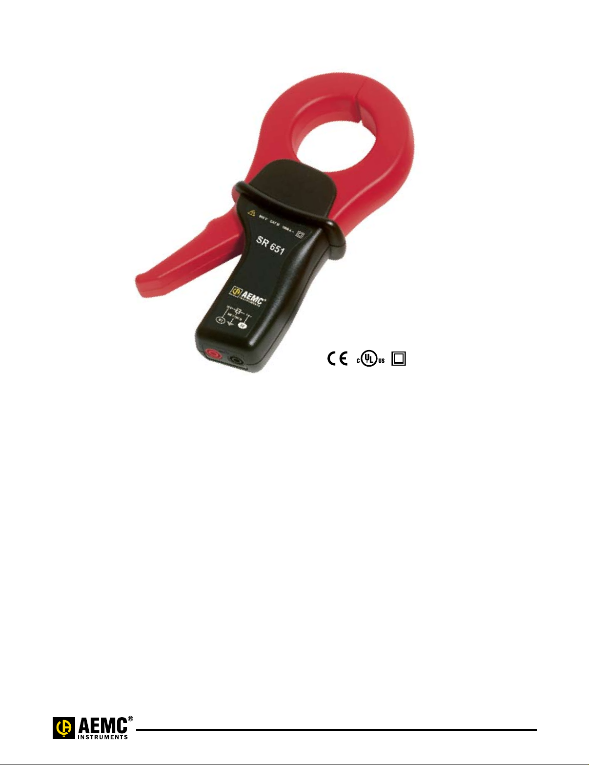
AC Current Probe Model SR651
The Model SR651 is designed for use
in industrial and utility environments.
The unique ergonomic design allows it
to easily clamp onto cables or small
bus bars. It is built to the highest safety
and performance standards including
the CE Mark and is UL approved for
Canada and United States.
Excellent transformation and low
phase shift, plus a broad frequency
response, permit accurate measurements of current for power and power
quality measurements. The high
quality magnetic cores and uniform
windings provide sensitivity for very
low level current measurements, as
well as measurements up to 1200A
The Model SR651 provides an
accurate voltage output of 1mV/A.
This voltage output enables
instruments without current ranges to
measure, display log currents through
an AC voltage range or measure very
low AC.
a c .
Features
• Measurement range of
100mA to 1200A
• Large jaw opening accommodates
conductors up to two 500MCM
conductors
• Ergonomic design and easy
operation
• Conforms to EN 61010, 600V Cat. III
safety standard
• Low phase shift for power
measurements
• Available with mV output signals
• Designed for DMMs, recorders,
loggers, oscilloscopes, power and
harmonic meters
• ULapprovedforCanadaand
United States
• DoubleInsulation
• CE Mark
a c
Applications
• Power quality measuring
• Low industrial loads
• Measuring around cable bundles
• Power load monitoring
• Waveform analysis
SR651_211345 (pdf) 0308 Rev. 05
Technical Assistance (800) 343-1391 www.aemc.com 1 of 4
Page 2
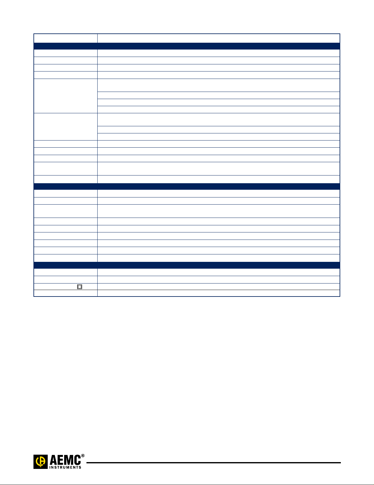
Specifications
MODEL SR651
ELECTRICAL
Nominal Range 1000A
Measurement Range 0.1 to 1200A
Transformation Ratio Voltage output
Output Signal 1mV/A
Accuracy (1000A Range)
1 to 50A ≤3% ± 0.1A
50 to 200A 1.5% of Reading
200 to 1000A 0.75% of Reading
1000 to 1200A 0.5% of Reading
Phase Shift (1000A Range)
50 to 200A 1.5°
200 to 1000A 0.75°
1000 to 1200A 0.5°
Overload 1200A for 40 min ON, 20 min OFF
Frequency Range 30Hz to 5kHz; current derating above 1kHz using the formula: 1000A x 1/F (in kHz)
Load Impedance 100kΩ min
Working/Common
Mode Voltage:
Output Termination Jack
MECHANICAL
Operating Temperature -14° to 122°F (-10° to 50°C)
Storage Temperature -4° to 158°F (-20° to 70°C)
Operating Relative
Humidity
Jaw Opening 2.25" (57mm) max
Maximum Conductor Size 2.05" (52mm)
Maximum Bus Bar Size One 1.95 x 0.19" (50 x 5mm)
Dimensions 4.37 x 8.50 x 1.77" (111 x 216 x 45mm)
Weight 1.21 lbs (550g)
Polycarbonate Material Handles: Polycarbonate + ABS, Gray, UL94 V0. Jaws: Polycarbonate, Red, UL94 V0
SAFETY
Electrical EN 61010-2-032
UL Approval Yes – Canada and United States
Double Insulation Yes
CE Mark Yes
Note: Reference conditions:
23 ± 3°K, 20 to 75% RH, 48 to 65Hz, external magnetic field <40A/m, no DC component, no external current carrying conductor,
test sample centered. Load impedance 1Ω.
a c /Aa c (1Va c @ 1000A)
600V Cat. III
0 to 85% @ 35°C
SR651_211345 (pdf) 0308 Rev. 05
Technical Assistance (800) 343-1391 www.aemc.com 2 of 4
Page 3

4.37" (111mm)
3.98" (101mm)
2.25" (57mm)
8.50" (216mm)
1.71" (43.5mm)
3.90" (99mm)
2.13"
(54.1mm)
1.22" (31mm)
1.38" (35mm)
1.77"
(45mm)
Ø=2.05" (52mm)
Conductor size
max.
Jacks:
Two standard
safety banana
jacks (4mm)
ORDERING INFORMATION CATALOG NO.
AC Current Probe Model SR651 (Jack – 1mV/A – 1000A max) ......................................Cat. #2113.45
Includes a user manual
Accessories (Optional)
Leads, set of two, 5 ft safety (1000V) ............................................................Cat. #2111.29
Banana plug adaptor (Safety Leads to nonrecessed plug) ...........................................Cat. #1017.45
Banana (Female) – BNC (Male) Adaptor .........................................................Cat. #2118.46
Technical Assistance (800) 343-1391 www.aemc.com 3 of 4
SR651_211345 (pdf) 0308 Rev. 05
Page 4

Contact Us
United States & Canada:
Chauvin Arnoux
d.b.a. AEMC
200 Foxborough Blvd.
Foxborough, MA 02035 USA
(508)698-2115•Fax(508)698-2118
www.aemc.com
Customer Support – for placing an order, obtaining price & delivery:
customerservice@aemc.com
Sales Department – for general sales information:
sales@aemc.com
Repair and Calibration Service – for information on repair & calibration, obtaining a user manual:
repair@aemc.com
Technical and Product Application Support – for technical and application support:
techinfo@aemc.com
Webmaster – for information regarding www.aemc.com:
webmaster@aemc.com
®
, Inc.
®
Instruments
South America, Central America, Mexico, Caribbean, Australia & New Zealand:
Chauvin Arnoux
d.b.a. AEMC
®
, Inc.
®
Instruments
15 Faraday Drive
Dover, NH 03820 USA
(978)526-7667•Fax(978)526-7605
export@aemc.com
www.aemc.com
All other countries:
Chauvin Arnoux SCA
190, rue Championnet
75876 Paris Cedex 18, France
33144854528•Fax33146277389
info@chauvin-arnoux.com
www.chauvin-arnoux.com
SR651_211345 (pdf) 0308 Rev. 05
Technical Assistance (800) 343-1391 www.aemc.com 4 of 4
 Loading...