

Page 1
Power & Energy Logger
Model PEL 105
Quick Start Guide
ENGLISH
www.aemc.com
Page 2

Statement of Compliance
Chauvin Arnoux®, Inc. d.b.a. AEMC® Instruments
certifies that this instrument has been calibrated using
standards and instruments traceable to international
standards.
We guarantee that at the time of shipping your
instrument has met its published specifications.
An NIST traceable certificate may be requested at
the time of purchase, or obtained by returning the
instrument to our repair and calibration facility, for
a nominal charge.
The recommended calibration interval for this
instrument is 12 months and begins on the date of
receipt by the customer. For recalibration, please
use our calibration services. Refer to our repair and
calibration section at www.aemc.com.
Serial #: ________________________________
Catalog #: 2137.57 / 2137.59
Model #: PEL 105
Please fill in the appropriate date as indicated:
Date Received: _________________________________
Date Calibration Due:
_______________________
Chauvin Arnoux®, Inc.
d.b.a AEMC® Instruments
www.aemc.com
Page 3
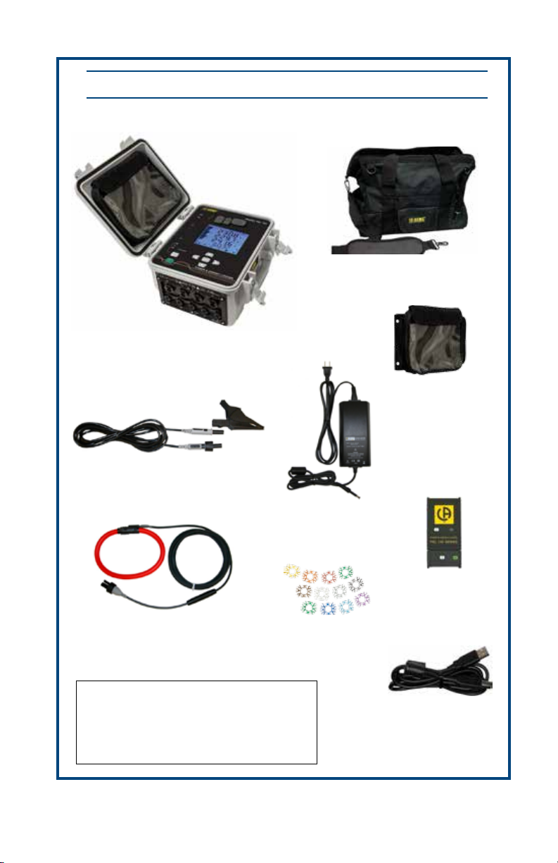
Shipping Contents:
(1) Power & Energy Logger
Model PEL 105
Cat. #2137.57 or Cat. #2137.59
PRODUCT PACKAGING
(1) Large Classic Tool Bag
Cat. #2133.73
Accessory Pouch
Cat. #2137.80
(5) Black Test Leads and Alligator Clips
(Only Shipped with PEL 105 Cat. #2137.59)
Also Includes:
Cat. #2140.73*
(*Replacement comes in Qty of 1)
®
(4) 24" AmpFlex
Model A196-24-BK
Cat. #2140.75
• 4 GB USB Stick (DataView/User Manual)
• 9.6V NiMh Battery - installed
(1) Power Adapter 110/240V
w/ Power Cord
Cat. #5000.19
(12) Color-coded
ID Markers
Cat. #2140.45
(1) USB SD-Card Adapter
Cat. #5000.45
(1) 5 ft USB Cable
Cat. #2140.46
• 8 GB SD-Card - installed
• High Voltage Warning/Caution Card
USB THUMB DRIVE: DataView® software and the user manual for the PEL 105 are stored
on the USB thumb drive supplied with the instrument.
Page 4
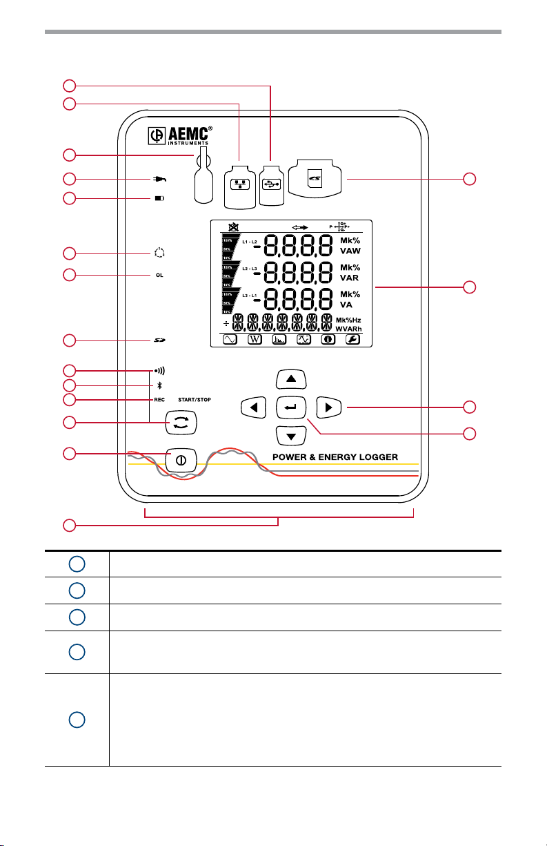
Front Panel
1
2
3
MODEL PEL 105
4
5
6
7
8
9
10
11
12
13
14
15
16
17
18
1
2
3
USB Port
Ethernet Port
Power Input
External Power LED (Green)
4
- ON: Instrument is currently running on external AC power.
- OFF: Instrument is running on battery or phase power.
Battery LED (Yellow/Red)
- ON:
Steady yellow: battery is actively charging.
5
Blinking yellow (once per second): battery is recovering from a full discharge.
Blinking red (twice per second): Battery is low and there is no external AC
power connected.
- OFF: Battery is fully charged.
Page 5
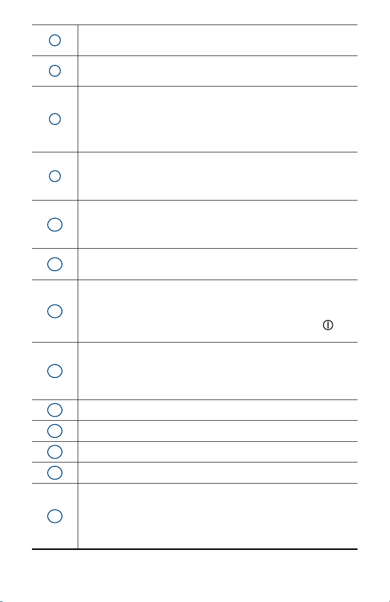
10
11
12
13
Phase Sequence (Red)
6
7
8
9
- ON (blinks once per second): Phase rotation not as expected
- OFF: Phase rotation order is as expected
Overload LED (Red)
- ON: At least one input is overloaded, or current inputs are mismatched.
- OFF: No input overload.
SD Card LED (Red/Green/Orange)
- Steady red: SD card is locked, unrecognized, or not present.
- Blinking red: SD card is initializing.
- Blinking orange: SD card is full.
- Steady green: SD card is present, recognized, and unlocked.
- Blinking green: SD card will be full before the end of the in-progress or pending
recording.
Wi-Fi LED (Green)
- ON:
Steady: Wi-Fi is enabled but not currently transmitting
Blinking: Wi-Fi is enabled and transmitting.
- OFF: Wi-Fi is disabled.
Bluetooth (Blue)
- ON:
Steady: Bluetooth is enabled but not currently transmitting.
Blinking: Bluetooth is enabled and transmitting.
- OFF: Bluetooth is disabled.
Recording (Green)
- Blinks twice every 5 seconds when recording.
- Blinks once every 5 seconds when not recording.
Control Button
- Starts or stops a data recording session.
- Enables or disables Bluetooth.
- Enables or disables Wi-Fi.
- When pressed and held down simultaneously with the Power button for 2
seconds, enables/disables the line voltage power feature.
Power Button
- Turns the instrument ON or OFF when running on battery power.
- Glows green when the instrument is running on phase voltage power.
- When not glowing, indicates the phase voltage feature is enabled but the
instrument is running on external AC or battery power.
- Blinks red when the phase voltage power feature is disabled.
14
15
16
17
18
Input Terminals
SD Card Slot
LCD Screen
Directional Buttons (Up, Down, Left, Right)
Enter Button
- In Configuration mode, selects a parameter for editing. This initiates the edit
mode. Pressing this button again saves the modification.
- In Measurement mode, displays additional information for some measurement
screens.
- In Energy mode, displays partial energy data.
- In all other modes, this button is inactive.
Page 6
Turning the Instrument ON/OFF
The instrument can operate on three different sources of power:
• External power provided by plugging into an AC outlet with the AC adapter. The instru-
ment will always run on external AC power when plugged in, even if phase voltage power
and/or battery power are also available.
• Phase power provided through line voltage at the terminals. If AC wall power is discon-
nected, the instrument runs on phase voltage power if it is available and enabled.
• Battery backup power. If neither external AC power nor phase voltage is available, the
instrument runs on battery power.
Turning the Instrument ON
• On AC power or phase voltage power, the instrument automatically turns ON when you
connect it.
• On battery power, you must press for two seconds to turn ON the instrument.
Turning the Instrument OFF
The procedure for turning OFF the instrument depends upon the power source.
• AC power (indicated when the
press
• Phase voltage power (indicated when glows green): Disconnect the voltage terminal
leads from the instrument, then press for two seconds and release it when all LEDs light
up simultaneously.
• Battery power: Press
ously.
for two seconds. When all LEDs light up simultaneously, release .
for two seconds and release it when all LEDs light up simultane-
LED is lit): Unplug the AC power adapter, and then
Installing DataView
®
DO NOT CONNECT THE INSTRUMENT TO THE COMPUTER BEFORE
INSTALLING THE SOFTWARE AND DRIVERS.
1. Insert the DataView thumb drive into an available USB port (wait for driver to be installed).
2. If Autorun is enabled, an AutoPlay window appears on your screen. Click “Open folder to
view files” to display the DataView folder. If Autorun is not enabled or allowed, use Windows
Explorer to locate and open the USB drive labeled “DataView.”
3. When the DataView folder is open, find the file Setup.exe and double-click it to run the installation program.
4. The DataView setup screen appears. In the upper left section of the screen, choose the language version you want to install. Then select DataView in the Options list and click Install.
5. The InstallShield Wizard welcome screen appears. The InstallShield Wizard leads you through
the installation process. As you complete these screens, be sure to click Power Energy Logger
when prompted to select the Control Panels to install.
6. When you have completed all screens, click Finish to leave the InstallShield Wizard. Then close
the DataView Setup screen. The DataView icon
along with the PEL Control Panel
icon.
now appears on your computer desktop,
Page 7

Connecting to the Computer
Before you can use the PEL Control Panel to communicate with your PEL 105, you must establish a
connection between the instrument and the computer. There are six types of connections available:
• USB cable connection
• Bluetooth wireless connection
• Wi-Fi direct connection
• Ethernet point-to-point cable connection
• Network connection via LAN or Wi-Fi
• Network connection via IRD server
To begin, ensure that you have installed DataView with the PEL Control Panel. Also ensure that the
required communication and connection drivers are installed on your computer. These drivers are
installed as part of the DataView installation process.
USB
1. Plug one end of the supplied cable into the instrument, and the other end into an available
USB port on the computer. The first time the instrument is connected via USB, drivers will be
installed. Wait for the drivers to finish installing before proceeding.
2. With the instrument connected, open the PEL Control Panel by clicking the
computer’s desktop.
3. In the menu bar at the top of the screen, select Instrument.
4. In the drop-down menu that appears, click the option Add an Instrument. This opens the Add
an Instrument Wizard dialog box.
5. Select USB as the connection type, and complete the Add and Instrument dialog. If you need
assistance, press the Help button.
icon on your
Bluetooth
To use this feature to connect to a computer, Bluetooth must be enabled on the instrument. Check
the Bluetooth
the button to enable Bluetooth.
Your computer must also be Bluetooth-enabled. When the computer is Bluetooth-ready, connect
the instrument as follows:
1. Open the Bluetooth Devices dialog on your computer to pair the instrument with your computer. Different operating systems have different steps for opening this dialog, so consult your
computer’s documentation for instructions.
2. When the dialog is displayed, click Add a Device. A dialog box appears listing the locally available Bluetooth devices.
3. Find the instrument, which will appear listed by its Bluetooth name. This name consists of the
prefix “PEL 105” plus any additional characters you add via the PEL Control Panel. Click the
name.
4. You are prompted to enter a pairing code, which for PEL 105 instruments is always 0000. After
you enter the code, click Next.
5. A screen appears informing you that the instrument has been successfully connected with the
computer. Click Close to exit the screen.
6. Open the PEL Control Panel. In the menu bar at the top of the screen, select Instrument.
7. In the drop-down menu that appears, click the option Add an Instrument. This opens the Add
an Instrument Wizard dialog box.
8. Select Bluetooth as the connection type, and complete the Add and Instrument dialog. If you
need assistance, press the Help button.
LED. If it is OFF, press and hold it down until the LED lights up. Then release
Page 8

Wi-Fi Direct Connection
Before you can connect through the PEL Control Panel, you must create a Wi-Fi connection between
the computer and instrument in Microsoft Windows. A direct Wi-Fi connection requires the instrument’s SSID number and (if required) password, which you can define by connecting the instrument
via USB cable, opening the Control Panel, and displaying the Configure dialog box, as instructed
by the Control Panel Help. The Configure dialog box includes fields for setting Wi-Fi connection
options.
In addition, Wi-Fi must be enabled on the instrument to use this feature. Check the Wi-Fi
If it is glowing steadily or blinking, Wi-Fi is enabled. If it is OFF, press
the
LED lights up. Then release the button to enable Wi-Fi. Your computer must also be Wi-
Fi-enabled.
When you have completed these tasks, open the PEL Control Panel and proceed as follows:
1. In the menu bar at the top of the screen, select Instrument.
2. In the drop-down menu that appears, click the option Add an Instrument.
3. Select Wi-Fi direct as the connection type, and complete the Add and Instrument dialog. If you
need assistance, press the Help button.
and hold it down until
LED.
Point-to-Point Ethernet Cable
To connect via point-to-point Ethernet, your computer must be equipped with an available Ethernet
port. You must also have an Ethernet cable (purchased separately).
1. Plug one end of the Ethernet cable into the instrument, and the other end into the Ethernet port
on the computer.
2. With the instrument connected, open the PEL Control Panel.
3. In the menu bar at the top of the screen, select Instrument.
4. In the drop-down menu that appears, click the option Add an Instrument. This opens the Add
an Instrument Wizard dialog box.
5. Select Point-to-point Ethernet cable (APIPA mode) as the connection type, and complete the
Add and Instrument dialog. If you need assistance, press the Help button.
Ethernet Network via LAN or Wi-Fi
For this type of connection, the instrument must be connected to a network accessible to the computer. The network connection can be either via LAN or Wi-Fi router. Consult your network administrator if you need assistance with this. When this connection is established, open the PEL Control
Panel and do the following:
1. In the menu bar at the top of the screen, select Instrument.
2. In the drop-down menu that appears, click the option Add an Instrument.
3. Select Ethernet (LAN or Wi-Fi) as the connection type, and complete the Add and Instrument
dialog. If you need assistance, press the Help button.
Network via IRD Server
An IRD server allows you to connect your computer to instruments on different networks. You must
first connect the instrument to a network that can access the internet. Consult your network administrator if you need assistance with this. When this connection is established, open the PEL Control
Panel and do the following:
1. In the menu bar at the top of the screen, select Instrument.
2. In the drop-down menu that appears, click the option Add an Instrument.
3. Select IRD server as the connection type, and complete the Add and Instrument dialog. If you
need assistance, press the Help button.
Page 9

Installing the SD-Card
Data recording sessions are stored in the included 8GB SD card, which also accepts FAT32 SDHC
cards up to 32GB capacity. If the SD card is unformatted, you will need to format it before use.
Formatting can be done through a Microsoft Windows command, or through the DataView PEL
Control Panel.
To install the SD card:
1. Locate the card slot on the front panel.
2. Ensure that the write-protect sliding tab on the card is in the “unlock” position (towards the
metal contacts).
3. Insert the SD card into the slot, with the metal contacts facing up (towards the top of the instrument)
4. Press the SD card into the slot until it clicks in place.
5. Press the attached cap into the card slot to ensure waterproofing.
6. If the SD Card is not formatted, the
PEL Control Panel. Click Instrument in the menu bar and select Configure. Then click Format
SD-Card in the General tab of the Configure Instrument dialog box, and click Yes to confirm.
When the card is installed and ready for use, the
press down on it until the card unclicks. It will pop up, allowing you to pull it from the slot
LED glows red. To format the installed card, open the
LED glows steady green. To remove a card,
Setting the Instrument Clock
Before using the instrument, you should ensure the instrument clock is set to the correct time zone.
By default the PEL 105 is set to Universal (UTC) time. To change this to another time zone, do the
following:
1. Open the PEL Control Panel and connect to the instrument, as instructed in the preceding section “Connecting to the Computer.”
2. Select Instrument in the menu bar, and select Configure. This opens the Configure dialog box.
3. In the General tab, click the Set Clock button to display the Date/Time dialog box.
4. You can synchronize the instrument’s clock with the computer’s clock, or use the Date and
Time fields to select another date and time.
You can click the Set Time Zone field to select a time zone adjustment. This defines the number
of hours by which the instrument’s local time differs from UTC time. For example, if you set the
adjustment to -4, the PEL 105 will display its local time as 4 hours “behind” UTC (e.g. when
local time is 12:00 PM, UTC is 4:00 PM).
Note that this adjustment also applies when you select Synchronize with PC Clock. When you
do this:
• The Control Panel reads your computer’s time and time zone information.
• The time is converted to UTC.
• The instrument’s UTC time is set to the computer’s UTC time.
• The time zone adjustment is applied to the UTC time to derive the instrument’s local time.
5. Complete the Date/Time dialog box and click OK. Then click OK in the Configure dialog box to
set the clock on the instrument.
Starting and Stopping a Recording
Before starting a recording, ensure that the instrument is not currently locked (the word LOCK
appears on the screen in Configuration mode). The instrument cannot begin a recording when it is
locked. The instrument is locked when:
• Being configured via the PEL Control Panel.
• Disabled through an option in the PEL Control Panel.
• A recording session is already in progress. Note that in this case the
so you can stop the recording. However, you cannot start a new recording if one is in progress.
If any of these situations is in effect, take appropriate action as necessary to unlock the instrument.
Then check the SD card
LED.
button remains active
Page 10

• If the LED is green, the SD card is ready to store recordings.
• If the LED glows steady red, ensure that:
• The SD card is installed.
• The write-protect sliding tab on the card is in the “unlock” position (towards the metal con-
tacts).
• The SD card is formatted. Formatting can be performed either through the PEL Control
Panel, or through a Windows command on your computer.
• If the LED blinks orange, the SD card is full. Download any data you want to save to your com-
puter, then erase the content of the card through the PEL Control Panel.
When the
PEL Control Panel, follow the instructions provided in the PEL Control Panel Help system. To record
through the instrument user interface, do the following:
1. Press
2. The
3. To stop a recording, press
To view the recording session, connect the instrument to your computer running the PEL Control
Panel, open the Help system, and follow the instructions for downloading and viewing recordings.
LED indicates the SD card is ready, you can begin recording. To do this through the
and hold it down until the LED lights. Then release .
LED should now blink twice every five seconds, indicating a recording is in progress.
and hold it down until the LED lights up, then release
.
Page 11

DISTRIBUTION SYSTEMS AND HOOK-UPS
VN V3 V2 V1
VE/GND
IN I3 I2 I1
L1
N
Source
Load
VN V3
Source Load
V2 V1
VE/GND
IN I3 I2 I1
L1
N
L2
L2 L1
N
VN V3
Source Load
V2 V1
VE/GND
IN I3 I2 I1
L1
L2
L3
L2 L1
L3
VN V3
Source Load
V2 V1
VE/GND
IN I3 I2 I1
L1
L2
L3
L2 L1
L3
The following hookup diagrams and connection instructions are for distribution systems supported by the PEL 105. The instrument must be appropriately configured for the hookup type.
Most configuration is performed through the PEL Control Panel, as described in the Help.
Some configuration can also be done via the instrument’s front panel, as described in the user
manual. Ensure that the current arrow on the sensor is directed towards the load. This ensures
proper phase angle for power measurements and other phase-sensitive measurements.
Single Phase 2-Wire (1P-2W)
• VN test lead to neutral (N)
• VE/GND test lead to ground (optional)
• V1 test lead to
• IN probe to neutral (optional)
• I1 probe to L1
3-Phase 3-Wire
(3P-3W
• VE/GND test lead to ground
• V1 test lead to L1
• V2 test lead to L2
• V3 test lead to L3
• I1 probe to LI
• I3 probe to L3
L1
∆ (2 current probes)
∆2)
Single Phase 3-Wire (1P-3W)
• VN test lead to neutral (N)
• VE/GND test lead to ground (optional)
• V1 test lead to L1
• V2 test lead to L2
• IN probe to neutral (optional)
• I1 probe to L1
• I2 probe to L2
3-Phase 3-Wire ∆ (3 current probes)
∆3)
(3P-3W
• VE/GND test lead to ground
• V1 test lead to L1
• V2 test lead to L2
• V3 test lead to L3
• I1 probe to L1
• I2 probe to L2
• I3 probe to L3
Page 12

3-Phase 3-Wire Open ∆ (2 current probes)
VN V3
Source Load
V2 V1
VE/GND
IN I3 I2 I1
L1
L2
L3
L2 L1
L3
VN V3
Source Load
V2 V1
VE/GND
IN I3 I2 I1
L1
L2
L3
L2
L3
L1
N
VN V3
Source Load
V2 V1
VE/GND
IN I3 I2 I1
L1
L2
L3
L2 L1
L3
VN V3
Source Load
V2 V1
VE/GND
IN I3 I2 I1
L1
L2
L3
L2
L3
L1
N
(3P-3WO2)
• VE/GND test lead to ground
• V1 test lead to L1
• V2 test lead to L2
• V3 test lead to L3
• I1 probe to L1
• I3 probe to L3
3-Phase 3-Wire Open ∆ (3 current probes)
(3P-3WO3)
• VE/GND test lead to ground
• V1 test lead to L1
• V2 test lead to L2
• V3 test lead to L3
• I1 probe to L1
• I2 probe to L2
• I3 probe to L3
3-Phase 3-Wire Y (2 current probes)
(3P-3WY2)
• VE/GND test lead to ground
• V1 test lead to L1
• V2 test lead to L2
• V3 test lead to L3
• I1 probe to L1
• I3 probe to L3
3-Phase 3-Wire Y (3 current probes)
(3P-3WY3)
• VE/GND test lead to ground
• V1 test lead to L1
• V2 test lead to L2
• V3 test lead to L3
• I1 probe to L1
• I2 probe to L2
• I3 probe to L3
Page 13

3-Phase 3-Wire ∆ Balanced
VN V3
Source Load
V2 V1
VE/GND
IN I3 I2 I1
L1
L2
L3
N
L2
L3
L1
N
VN V3
Source Load
V2 V1
VE/GND
IN I3 I2 I1
L1
L2
L3
N
L2
L3
L1
N
VN V3
Source Load
V2 V1
VE/GND
IN I3 I2 I1
L1
L2
L3
L2 L1
L3
VN V3
Source Load
V2 V1
VE/GND
IN I3 I2 I1
L1
L2
L3
N
L2
L3
L1
N
(1 current probe) (3P3W∆b)
• VE/GND test lead to ground
• V1 test lead to L1
• V2 test lead to L2
• I3 probe to L3
3-Phase 4-Wire Y (3 current probes)
(3P-4WY)
• VE/GND test lead to ground
• VN test lead to neutral (N)
• V1 test lead to L1
• V2 test lead to L2
• V3 test lead to L3
• IN probe to neutral
• I1 probe to L1
• I2 probe to L2
• I3 probe to L3
3-Phase 4-Wire Y Balanced (3P-4WYb)
• VE/GND test lead to ground
• VN test lead to neutral (N)
• V1 test lead to L1
• IN probe to neutral
• I1 probe to L1
3-Phase 4-Wire Y 2½ Element
(3P-4WY2)
• VE/GND test lead to ground
• VN test lead to neutral (N)
• V1 test lead to L1
• V3 test lead to L3
• IN probe to neutral
• I1 probe to L1
• I2 probe to L2
• I3 probe to L3
Page 14

3-Phase 4-Wire ∆ (3P-4W∆)
VN V3
Source Load
V2 V1
VE/GND
IN I3 I2 I1
L1
L2
L3
N
L1L2L3
N
VN V3
Source Load
V2 V1
VE/GND
IN I3 I2 I1
L1
L2
L3
N
L1L2L3
N
VN V3
Source Load
V2 V1
VE/GND
IN I3 I2 I1
+1
VN V3
Source Load
V2 V1
VE/GND
IN I3 I2 I1
+1
+2
• VE/GND test lead to ground
• VN test lead to neutral (N)
• V1 test lead to L1
• V2 test lead to L2
• V3 test lead to L3
• IN probe to neutral
• I1 probe to L1
• I2 probe to L2
• I3 probe to L3
3-Phase 4-Wire Open ∆
• VE/GND test lead to ground
• VN test lead to neutral (N)
• V1 test lead to L1
• V2 test lead to L2
• V3 test lead to L3
• IN probe to neutral
• I1 probe to L1
• I2 probe to L2
• I3 probe to L3
DC 2-Wire (dC-2W)
• VE/GND test lead to ground
• VN test lead to the common conductor.
• V1 test lead to conductor +1
• IN probe to the common conductor
• I1 probe to conductor +1
DC 3-Wire (dC-3W)
• VE/GND test lead to ground
• VN test lead to the common conductor
• V1 test lead to conductor +1
• V2 test lead to conductor +2
• IN probe to the common conductor
• I1 probe to conductor +1
• I2 probe to conductor +2
Page 15

DC 4-Wire (dC-4W)
VN V3
Source Load
V2 V1
VE/GND
IN I3 I2 I1
+1
+2
+3
• VE/GND test lead to ground
• VN test lead to the common conductor
• V1 test lead to conductor +1
• V2 test lead to conductor +2
• V3 test lead to conductor +3
• IN probe to the common conductor
• I1 probe to conductor +1
• I2 probe to conductor +2
• I3 probe to conductor +3
Page 16

Repair and Calibration
To ensure that your instrument meets factory specifications, we recommend
that it be scheduled back to our factory Service Center at one-year intervals for
recalibration, or as required by other standards or internal procedures.
For instrument repair and calibration:
You must contact our Service Center for a Customer Service Authorization
Number (CSA#). This will ensure that when your instrument arrives, it will be
tracked and processed promptly. Please write the CSA# on the outside of the
shipping container. If the instrument is returned for calibration, we need to
know if you want a standard calibration, or a calibration traceable to N.I.S.T.
(Includes calibration certificate plus recorded calibration data).
Ship To: Chauvin Arnoux
®
, Inc. d.b.a. AEMC® Instruments
15 Faraday Drive
Dover, NH 03820 USA
Phone: (800) 945-2362 (Ext. 360)
(603) 749-6434 (Ext. 360)
Fax: (603) 742-2346 or (603) 749-6309
E-mail: repair@aemc.com
(Or contact your authorized distributor.) Costs for repair, standard calibration,
and calibration traceable to N.I.S.T. are available.
NOTE: You must obtain a CSA# before returning any instrument.
Technical and Sales Assistance
If you are experiencing any technical problems, or require any assistance with
the proper operation or application of your instrument, please call, mail, fax or
e-mail our technical support team:
Chauvin Arnoux
200 Foxborough Boulevard
Foxborough, MA 02035 USA
Phone: (800) 343-1391
(508) 698-2115
Fax: (508) 698-2118
E-mail: techsupport@aemc.com
www.aemc.com
NOTE: Do not ship instruments to our Foxborough, MA address.
®
, Inc. d.b.a. AEMC® Instruments
Page 17

Limited Warranty
The Model PEL 105 is warranted to the owner for a period of one year from the
date of original purchase against defects in manufacture. This limited warranty
is given by AEMC® Instruments, not by the distributor from whom it was
purchased. This warranty is void if the unit has been tampered with, abused or
if the defect is related to service not performed by AEMC® Instruments.
Full warranty coverage and registration is available on our website:
www.aemc.com/warranty.html.
Please print the online Warranty Coverage Information for your records.
®
What AEMC
Instruments will do: If a malfunction occurs within the
warranty period, you may return the instrument to us for repair, provided
we have your warranty registration on file or a proof of purchase. AEMC®
Instruments will, at its option, repair or replace the faulty material.
Warranty Repairs
What you must do to return an Instrument for Warranty Repair:
First, request a Customer Service Authorization Number (CSA#) by phone or
e-mail from our Service Department, then return the instrument along with the
signed CSA Form. Please write the CSA# on the outside of the shipping container. Return the instrument, shipment pre-paid to:
®
Ship To: Chauvin Arnoux
, Inc. d.b.a. AEMC® Instruments
15FaradayDrive•Dover,NH03820USA
Phone: (800) 945-2362 or (603) 749-6434 (Ext. 360)
E-mail: repair@aemc.com
Caution: To protect yourself against in-transit loss, we recommend you insure
your returned material.
NOTE: You must obtain a CSA# before returning any instrument.
Page 18

Notes:
Page 19

Page 20

05/16
99-MAN 100428 v2
Chauvin Arnoux
®
, Inc. d.b.a. AEMC® Instruments
15FaradayDrive•Dover,NH03820USA•Phone:(603)749-6434•Fax:(603)742-2346
www.aemc.com
 Loading...