

Page 1

Portable multimeters
with digital display
ASYC-IV
MTX 3290 - 6000 cts
MTX 3291- 60000 cts
Operating instructions
Pôle Test et Mesure CHAUVIN ARNOUX
Page 2

General directions
Contents
General directions ............................................................................................................................................ 3
Introduction, Precautions and safety measures ............................................................................................................. 3
Special functions ........................................................................................................................................................... 4
Symbols on the instrument ............................................................................................................................................ 5
Warranty, Maintenance, metrological verification, Repair under warranty ..................................................................... 6
Maintenance .................................................................................................................................................................. 7
Replacing the fuse ......................................................................................................................................................... 7
Rechargeable and primary batteries ............................................................................................................................. 7
Communication interface ............................................................................................................................................... 7
Description of the instruments .........................................................................................................................
MTX 3290 frontal panel, back, terminal block................................................................................................................ 8
MTX 3291 frontal panel, back, terminal block................................................................................................................ 9
Display unit .................................................................................................................................................................. 10
Switch .......................................................................................................................................................................... 13
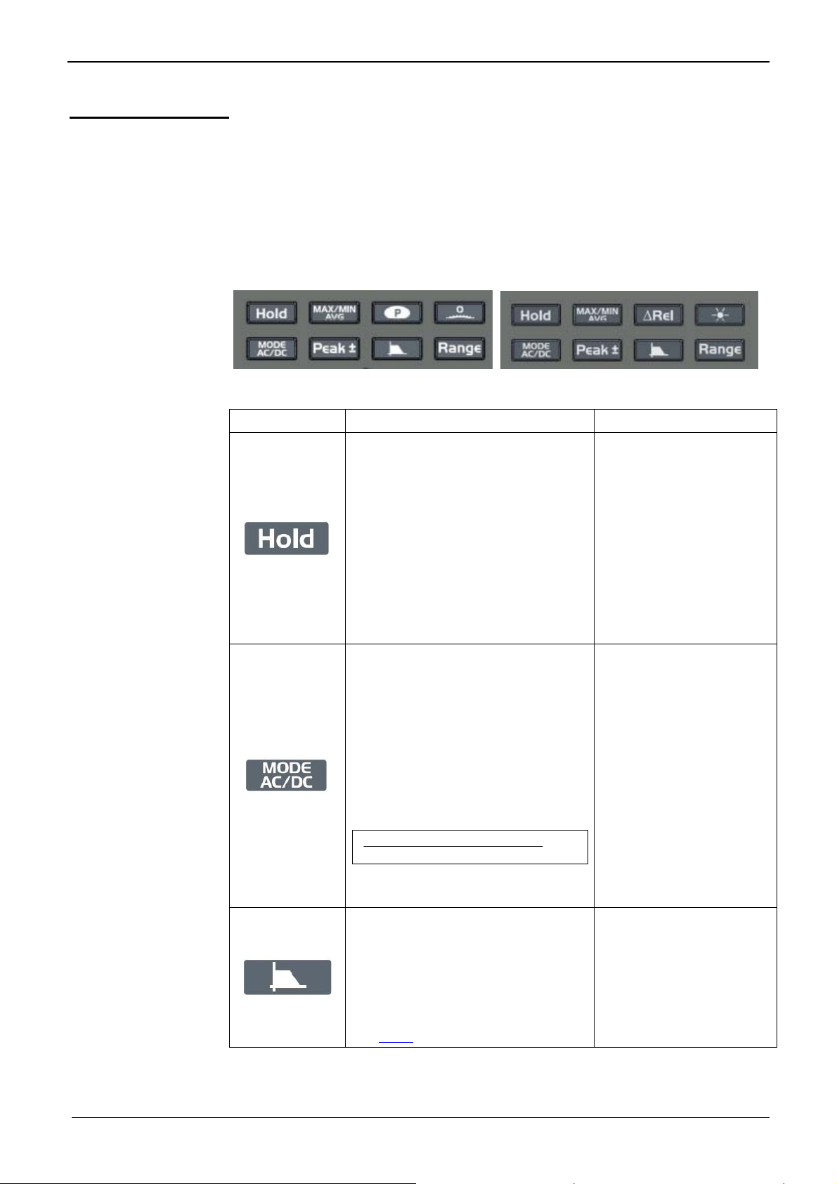
Keypad ........................................................................................................................................................................ 15
Getting started ................................................................................................................................................ 18
Preparation for use ...................................................................................................................................................... 18
Functional description ................................................................................................................................... 19
1. MAX MIN AVG mode .............................................................................................................................................. 19
2. PEAK mode ............................................................................................................................................................. 22
3. ΔREL mode ............................................................................................................................................................. 23
4. "CLAMP" function .................................................................................................................................................... 25
Functions of the switch and keys ................................................................................................................................. 26
How are the various quantities measured? ................................................................................................. 28
1. Voltage measurement ............................................................................................................................................. 28
2. Current measurement ............................................................................................................................................. 29
3. Frequency measurement......................................................................................................................................... 31
4. Resistance measurement ........................................................................................................................................ 31
5. Audible continuity measurement ............................................................................................................................. 32
6. Diode test ................................................................................................................................................................ 32
7. Capacitance measurement...................................................................................................................................... 33
8. Temperature measurement ..................................................................................................................................... 34
9. Measurement on an MLI type speed variator .......................................................................................................... 35
10. Resistive power (MTX 3291) ................................................................................................................................. 37
11. dBm decibels in power (MTX 3291) ...................................................................................................................... 38
SX-DMM software ........................................................................................................................................... 39
Technical characteristics of MTX 3290 ........................................................................................................ 40
Technical characteristics of MTX 3291 ........................................................................................................ 50
General characteristics ................................................................................................................................. 61
Environmental conditions ............................................................................................................................................ 61
Power supply ............................................................................................................................................................... 61
Display ........................................................................................................................................................................ 61
Safety, CEM ................................................................................................................................................................ 61
Mechanical characteristics ........................................................................................................................... 61
Housing ....................................................................................................................................................................... 61
Supply ............................................................................................................................................................. 62
2 6,000- and 60,000-count digital multimeters
Page 3
General directions
General directions
Introduction
Congratulations! You have just acquired a portable multimeter with a
display digital.
We thank you for this sign of confidence in the quality of our products.
The line of instruments to which it belongs comprises the following models:
Display digital, monochrome,
Power supply 4 R6 primary batteries (AA format) or 4 rechargeable batteries
Counts 6000 60000
Communication - IR/USB
It complies with safety standard NF EN 61010-1 + NF EN 61010-2-030
concerning electronic measuring instruments.
For best results, read this manual closely and observe the precautions of use.
Failure to observe these warnings and/or directions may damage the instrument
and/or its components and may endanger the user.
MTX 3290 MTX 3291
digital, monochrome,
(70x52)
backlit (70x52)
Precautions and safety measures
before use
during use
• This instrument is been designed to be used as follows:
- indoors
- in an environment of pollution degree 2
- at an altitude of less than 2000m
- at a temperature between -10°C and 55°C
- at a relative humidity below 80% up to 31°C.
• The safety of any system incorporating the instrument is the responsibility
of the system integrator.
• Can be used for measurements on circuits:
- MTX 3290: 600V, CAT III and 300V, CAT IV.
- MTX 3291: 1000V CAT III and 600 CAT IV.
However, some accessories may lead to the use of this instrument on
circuits of a lower voltage and category.
• Comply with the environmental and storage conditions.
• Check the integrity of the guards and insulation of the accessories. Any item
of which the insulation is deteriorated (even partially) must be removed from
service and scrapped. A change of colour of the insulation is a sign of
deterioration.
• Read closely all notes preceded by the
• As a safety measure, use only the appropriate leads and accessories
supplied with the instrument or approved by the manufacturer.
symbol.
6,000- and 60,000-count digital multimeters 3
Page 4
General directions
General directions (continued)
Safety feature
Features
protecting the
measurement
inputs
• It is impossible to open the battery or fuse compartment without first
disconnecting the measurement leads.
• During a measurement exceeding 60V
the display unit
• Automatic detection of a connection to the "Ampere" terminal (for both
voltage and current measurements)
• When the maximum permanent voltage or current that can be measured is
exceeded, an intermittent audible signal warns of the risk of an electric
shock.
These multimeters have several features to protect them:
• varistor protection that clips transient voltage surges on the
measurement terminals.
• PTC (Positive Temperature Coefficient) protection against permanent
overvoltages less than or equal to 1000V during resistance,
capacitance, and diode test measurements.
This protection is reset automatically after the overload.
• a fuse that provides protection during current measurements.
- MTX 3290: 10A
- MTX 3291: 11A
DC or 25VAC the symbol blinks on
Special functions
Automatic
detection
Automatic
switching off
Warning
signals
The number of input terminals is limited to 3: V, COM, A. Connecting the
lead to the "Ampere" terminal automatically selects the corresponding
function.
* When a change of function by the command keypad is
incompatible with the connection of the lead, it triggers an
audible or visual (LEADS) alert.
The current measurement is made with automatic peak range full-scale.
During a current measurement, an audible alert is triggered in the event of a
prolonged absence of current.
If the function is validated ( ), the device is automatically switched off after
30 mn of operation if there has been no action on the front panel during this
time.
* Automatic switching off is disabled:
- in the MAX, MIN, AVG, PEAK Surveillance mode
- in the Communication mode
- if there is a voltage >60V
multimeter.
An intermittent audible signal is emitted in all "Voltage" and "Current" settings if
the max. permanent value the device can measure is exceeded. It is
accompanied by display of the "O. L" acronym and of the
display unit.
This symbol is activated when the voltage on the "V" input exceeds 60V
AC in the "Voltage" setting or when the current injected between the A and
25V
COM terminals exceeds 10A.
DC or 25VAC on the terminals of the
symbol on the
DC or
4 6,000- and 60,000-count digital multimeters
Page 5
General directions
General directions (continued)
Definitions of the
measurement
categories
Warning! Using a measuring instrument, a lead, or an accessory belonging to a lower
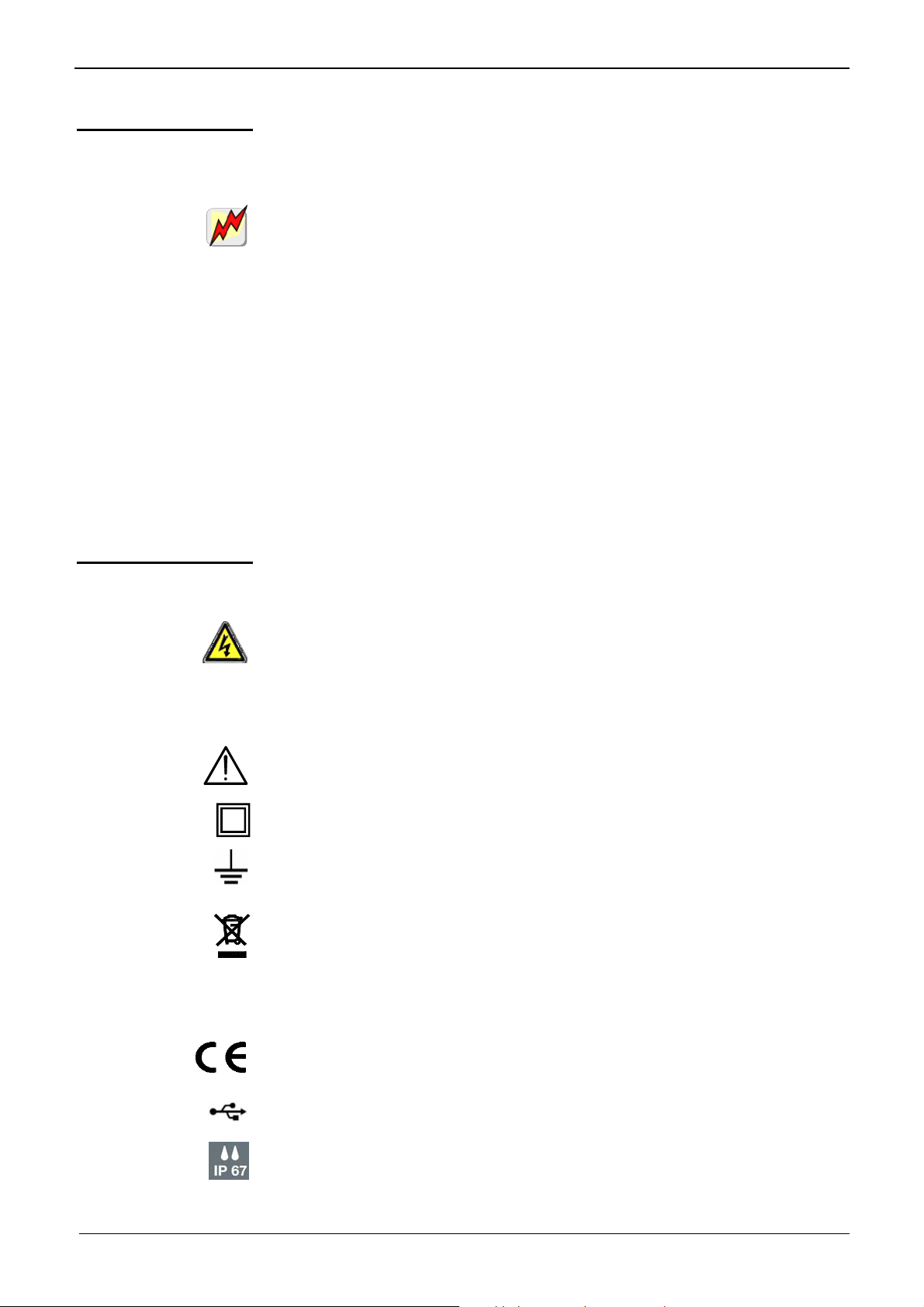
Symbols on the instrument
CAT II: Test and measurement circuits directly connected to the points of use
of the low-voltage network (power outlets and other similar points).
E.g.: Measurements on the network circuits of household appliances, portable
tools, and similar devices.
CAT III: Test and measurement circuits connected to parts of the low-voltage
network of the building.
E.g.: Measurements on distribution panels (including secondary meters), circuitbreakers, wiring including cables, bus bars, branch boxes, disconnecting
switches, power outlets in the fixed installation, and industrial appliances and
other equipment, such as motors permanently connected to the fixed
installation.
CAT IV: Test and measurement circuits connected to the source of the lowvoltage network of the building.
E.g.: Measurements on devices installed before the main fuse or the circuitbreaker of the building installation.
measurement or voltage category derates the resulting system (instrument
+ leads + accessories) to the lowest measurement category and/or service
voltage of any of the components.
Risk of electric shock: directions for connection and disconnection of the inputs.
Always connect the probes or adapters to the instrument before connecting
them to the measurement points. Always disconnect the probes or cords from
the measurement points before disconnecting them from the instrument. These
directions apply before the instrument is cleaned.
Warning: Hazard. The operator must refer to the manual each time this danger
symbol is encountered.
Device entirely protected by double insulation or reinforced insulation.
Earth
In the European Union, this product is subject to selective collection for the
recycling of electrical and electronic equipment waste in accordance with
Directive WEEE 2002/96/EC: this equipment must not be treated as ordinary
waste. The spent batteries must not be treated as ordinary waste. Take them in
to the appropriate collection point for recycling.
The CE marking indicates conformity with the European "Low Voltage", "EMC",
"WEEE" and "RoHS" directives.
USB (MTX 3291)
IP67
6,000- and 60,000-count digital multimeters 5
Page 6
General directions
General directions (continued)
Warranty
Maintenance, metrological verification
This equipment is warranted for 3 years against any defect of materials or
workmanship, in accordance with the general terms of sale. During the
warranty period, the instrument may be repaired only by the manufacturer, who
reserves the right to repair the instrument or to replace it or part of it. If the
equipment is returned to the manufacturer, the cost of transport to the
manufacturer is borne by the customer.
The warranty does not apply following:
• improper use of the equipment or use in association with incompatible
equipment
• modification of the equipment without the explicit permission of the
manufacturer's technical staff
• maintenance done by a person not approved by the manufacturer
• adaptation to a particular application not anticipated in the definition of the
equipment or by the user manual
• a shock, a fall, or flooding.
Before opening the instrument, you must disconnect it from line power and
from the measurement circuits and make sure that you are not charged with
static electricity, which might destroy internal components. An adjustment,
maintenance, or repair of the live instrument must be undertaken only by
personnel who are qualified and have familiarized themselves with the
directions in this manual.
We recommend a verification of this instrument at least once a year. For
checking and calibration, contact one of our accredited metrology laboratories
(information and contact details available on request), at our Chauvin Arnoux
subsidiary or the branch in your country.
Unpacking, repacking
Repair under warranty and post warranty
All of the equipment has undergone mechanical and electrical checks before
being dispatched. When you receive it, carry out a quick check to detect any
deterioration that may have occurred during transport. Should the need arise,
immediately contact our sales department and notify the carrier of the customary
reservations.
Use the original packaging to reship the equipment, if possible. Indicate as
clearly as possible, by a note attached to the equipment, the reasons for the
transfer.
For all repairs before or after expiry of warranty, please return the device to your
distributor.
6 6,000- and 60,000-count digital multimeters
Page 7
General directions
General directions (continued)
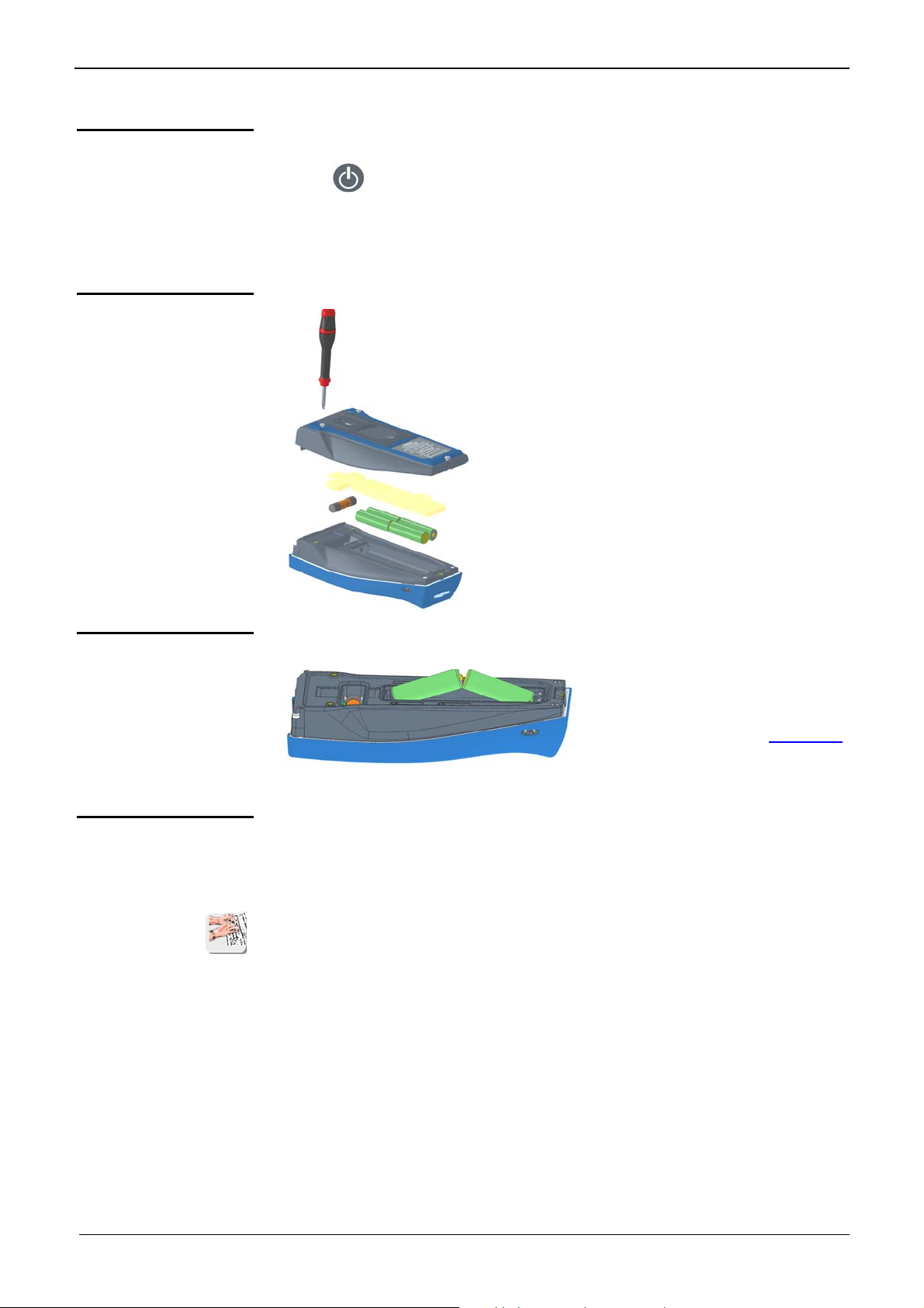
Maintenance
Replacing the fuse
• Disconnect everything connected to the instrument and press the ON/OFF
key (
• Use a soft cloth, moistened with soapy water.
• Rinse with a damp cloth and dry rapidly with a dry cloth or forced air.
• Make sure that no foreign objects interfere with the operation of the device
by which the leads are snapped into place.
).
y Before replacing the fuse (reached by
opening the bottom compartment), disconnect
the instrument from any source of current.
During the replacement, make sure that only a
fuse of the appropriate rating and specified
type is used. Using another type of fuse and
shorting the fuse holder are strictly forbidden.
y Checking the current fuse:
Fuse: SIBA/5019906
MTX 3291: 11A: 10x38 – 1,000V - F
breaking capacity: >20kA
MTX 3290: 10A: 6x32 - 600V - F
breaking capacity: >50kA
Rechargeable and primary batteries
Active
communication
interface
(MTX 3291 only)
The multimeter is powered by primary or rechargeable batteries (see above).
To charge the rechargeable
batteries (set of 4 NI-MH LSD
batteries), use an external rapid
charger, available as an accessory
* After replacing the batteries,
wait 10s before switching the instrument back on.
The multimeter can communicate with a PC via the USB link.
The basic version includes a USB link using an isolated optical USB cord (type
HX0056Z) and SX-DMM software, plus Labview and Labwindows drivers to
program the devices.
* MTX 3291: They can also be programmed via the SCPI protocol:
- to program via Labview/LW
- to recover data or program the instrument using the software
- to calibrate the MTX 3291
.
6,000- and 60,000-count digital multimeters 7
Page 8
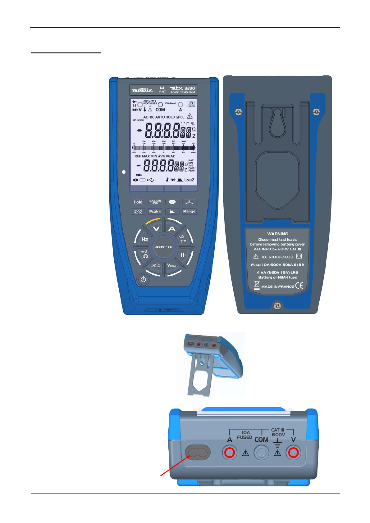
Description of the instruments
Description of the instruments
MTX 3290
Frontal panel
Back
Prop
Terminal block
Optical connector:
not active !
8 6,000- and 60,000-count digital multimeters
Page 9
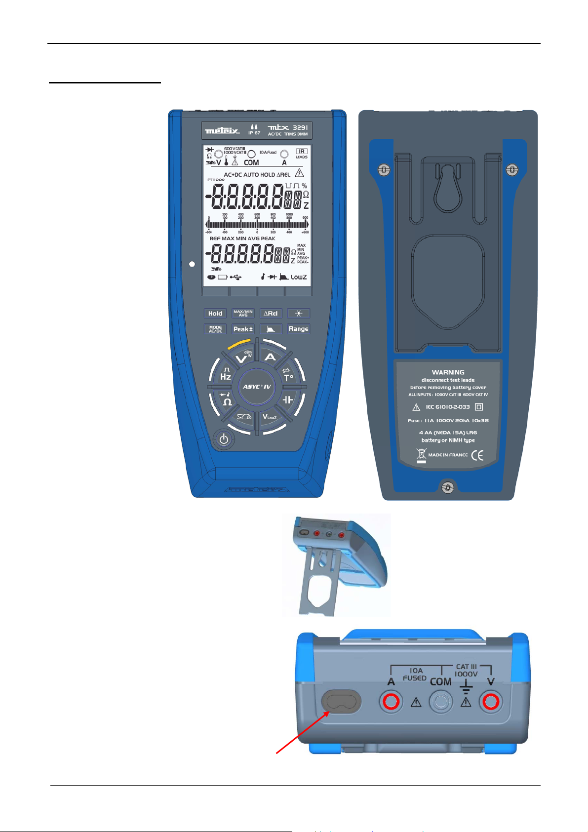
Description of the instruments
Description of the instruments (continued)
MTX 3291
Frontal panel
Back
Prop
Terminal block
Optical connector: active!
6,000- and 60,000-count digital multimeters 9
Page 10
Description of the instruments
Description of the instruments (continued)
Display unit
The display is in two parts:
• A digital display for convenient reading of the digits:
- main display unit: 12.7mm
- secondary display unit: 9.7mm
• The "bargraph" display (61 segments) with scale (indication of the
measurement range) for an analogue reading
Quantities
measured
double 6,000-pts display
LowZ AC voltage measurement at low impedance (VLowZ)
• V
• V
AC AC voltage measurement
• V
AC/DC DC or AC+DC voltage measurement at high impedance (V)
MTX3290
double 60,000-pts display
MTX 3291
• A Current measurement A
• Hz Frequency measurement
• Resistance measurement
• µF Capacitance measurement
• T° Temperature measurement
• ms Measurement of the period
• % Measurement of relative value
Units
• V Volt
• A Ampere
• Hz Hertz
• Ohm
• F Farad
• °F Degree Fahrenheit
• °C Degree Celsius
• ms millisecond
• k kilo k-kHz
• M Mega M-MHz
• n nano nF
• µ micro µV-µA -µF
• m milli mV-mA -mF
• % Percentage
10 6,000- and 60,000-count digital multimeters
Page 11
Description of the instruments
Description of the instruments (continued)
Symbols Designation
AC
DC
AC+DC
AUTO
Measurement of the AC signal
Measurement of the DC signal
Measurement of the AC and DC signal
Automatic range switching
Δ REL
REF
HOLD
MAX MIN AVG
MAX
MIN
AVG
PEAK
PEAK+
PEAK-
.run r.un ru.n
----- Frequency measurement impossible
O.L
USER
BASIC
Z
Z
Ω
Ω
%
PT100
PT1000
Values relative to a reference
Reference value
Storage and display of stored values
Value (surveillance)
Maximum value
Minimum value
Mean value
Peak value
Maximum peak value
Minimum peak value
Capacitance meter, acquisition in progress
Overshoot of the measurement capacities
USER mode (on main display unit)
BASIC mode (on main display unit)
Hertz symbol (main display unit)
Hertz symbol (secondary display unit)
Ohm (main display unit)
Ohm (secondary display unit)
Percentage
Positive pulse
Negative pulse
Symbol for temperature measurement using a Pt100 probe
Symbol for temperature measurement using a Pt1000 probe
LEADS
LowZ
♪
Symbol for measurement using a current clamp
Function selected incompatible with the connection of the lead
Low-impedance voltage measurement
Symbol of the audible continuity measurement
Symbol of the measurement and testing of a semiconductor junction
Warning, possibility of electric shock (∗)
USB communication (MTX 3291)
300Hz filter
Auto power OFF deactivated (permanent mode)
6,000- and 60,000-count digital multimeters 11
Page 12
Description of the instruments
Description of the instruments (continued)
600V CAT III
1000V CAT III
This symbol indicates the battery charge level.
Volt, Ohm, temperature, etc. measurement input
COM measurement input
Ampere measurement input
Input indication
Input indication
Isolated optical link (USB) input
Display of unit on the main display unit (2x14 segments)
Display of unit on the secondary display unit (2x14 segments)
Identifies the reminder of the display zone connection
∗) When voltages exceeding 60 VDC or 25 VAC are measured, the symbol flashes on the display unit.
(
12 6,000- and 60,000-count digital multimeters
Page 13
Description of the instruments
Description of the instruments (continued)
Switch
MTX 3290
Keys of the switch
Orange LEDs around the highly reliable virtual switch indicate the measurement
function chosen. The keys of the switch have priority over the action of the keys
of the keypad. The change from one function to another resets the configuration
of the measurement mode.
Short press Successive short presses
Current measurement
Temperature measurement
Capacitance measurement
Low-impedance AC voltage
measurement (VLowZ)
Selection of the type of probe:
Pt100, Pt1000
Current measurement using a
current clamp
Resistance measurement,
audible continuity
measurement, diode test
Frequency measurement
Voltage measurement
Selection of the transformation ratios
1, 10, 100, 1,000mV/A
Selection of the continuity, diode
functions
6,000- and 60,000-count digital multimeters 13
Page 14
Description of the instruments
Description of the instruments (continued)
MTX 3291
Keys of the switch
Short press Successive short presses
Current measurement
Temperature measurement
Capacitance measurement
Low-impedance AC voltage
measurement (VLowZ)
Current measurement using a
current clamp
Resistance measurement,
audible continuity
measurement, diode test
Frequency measurement
Selection of the type of probe:
Pt100, Pt1000
Selection of the transformation ratios
1, 10, 100, 1,000mV/A
Selection of the continuity, diode
functions
Selection of the functions:
- Positive duty cycle
- Negative duty cycle
- Positive pulse width
- Negative pulse width
14 6,000- and 60,000-count digital multimeters
Voltage measurement
Selection of the functions:
dBm, W
Page 15
Description of the instruments
Description of the instruments (continued)
Keypad
Function keys
The keypad has the following function keys:
The keys are taken into account and applied when pressed. If the key press is
validated, the instrument beeps.
Two types of action are possible:
• Short press Æ press lasting <2 seconds, validated by a beep as
soon as the key press is detected.
• Long press Æ press lasting >2 seconds, validated by a beep as soon as
the key press is detected.
MTX 3290
Successive short presses Long press
Activation/deactivation of storage of
the measurements and of the
quantities at a given time:
- Hold of the display without stopping
the acquisitions. The bargraph
continues to operate normally.
- Exit from the HOLD mode
In the MAX/MIN/AVG PEAK mode,
when the HOLD is active, the blinking
of the "MAX MIN AVG PEAK" symbol
indicates that acquisition continues as
a background task.
Choice of coupling AC, DC, AC+DC:
- Access to various parameters
ÆIn dBm: change of impedance 50,
75, 90, 600 (MTX 3291 only)
ÆIn temperature: the main display
unit indicates the temperature in °C,
the other in °F
ÆIn the REL mode, the key is used
to change from (present value –
reference value) to
Present value – reference value
Reference value
The value is displayed in %.
(MTX 3291 only)
Activation/deactivation of the low-pass
filter 300Hz:
The low-pass filter (4th order) makes
it possible to measure the RMS
voltage delivered by an MLI type
speed controller (for asynchronous
motor).
See curve
, p. 49 and 60.
x100
MTX 3291
- Hold of the display after
stabilization of the
measurement (Auto
HOLD)
- Exit from the
Auto HOLD mode
Activation/deactivation of
auto power off (APO)
(MTX 3291 only)
Activation/deactivation of
the key-press beep
6,000- and 60,000-count digital multimeters 15
Page 16
Description of the instruments
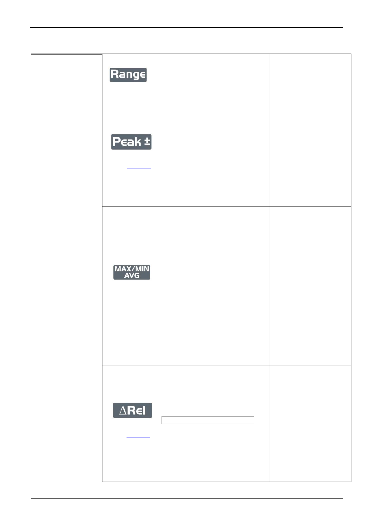
Description of the instruments (continued)
Manual selection of measurement
range: the range defines the maximum
measurement range the instrument can
cover.
Used to return to Auto
Range mode.
The Auto Range mode is default.
Activation of the Peak+ Peak-
measurements:
- Peak+: displays the maximum
instantaneous peak value of the
measurement.
- Peak-: displays the minimum
instantaneous peak value of the
(∗)
(∗) see example
p. 22.
measurement.
st
press: recording of PEAK+, PEAK-
- 1
(on the 2nd display unit).
The PEAK+ value is displayed as
Exit from the Peak mode
default.
- Subsequent presses: look-up of stored
values (volatile).
Activation of the MAX, MIN, AVG
measurements:
- MAX and MIN inform the highest and
lowest values of the effective
measurement
- AVG: displays the mean value of the
signal since the key press
Time-stamped value for the min and the
(∗)
(∗) see example
p. 19.
max [temporary display (4s) on the
main display unit, followed by return to
present value]
If the time (h:min:sec) exceeds
(9:59:59), is displayed ----.
Exit from the
MAX, MIN, AVG mode
(MTX 3291 only)
st
press: recording of the MAX, MIN,
- 1
AVG (on the 2nd display unit).
The max. value is displayed by
default.
- Subsequent presses: look-up of the
stored values (volatile).
Activation of the relative display mode:
- Display and storage of the reference
and differential values in the unit of
the quantity measured.
st
press: activates the relative mode
- 1
∆REL
(∗)
(∗) see example
p. 23.
(present value – reference value)
and stores the measured value that
will be used as reference.
- "REF" indicates the storage of the
Exit from the ∆REL mode
reference.
- Subsequent presses: toggles the
display between the measured value
and the relative measurement ∆REL.
16 6,000- and 60,000-count digital multimeters
Page 17
Description of the instruments
Description of the instruments (continued)
* Remark 1
* Remark 2
- The 0 centre bargraph is managed automatically in IDC and VDC (MTX 3291
only).
When the multimeter is switched on:
- 1st press on
segments of the display unit.
nd
press Æ display of model and version (US/Europe)
- 2
rd
- 3
press Æ software version (display unit 1) and keyboard and display unit
board versions (display unit 2)
th
press Æ normal operation. An audible beep acknowledges key presses.
- 4
USER/BASIC mode: During power up, the device is in BASIC mode (default
configuration Volt AC+DC).
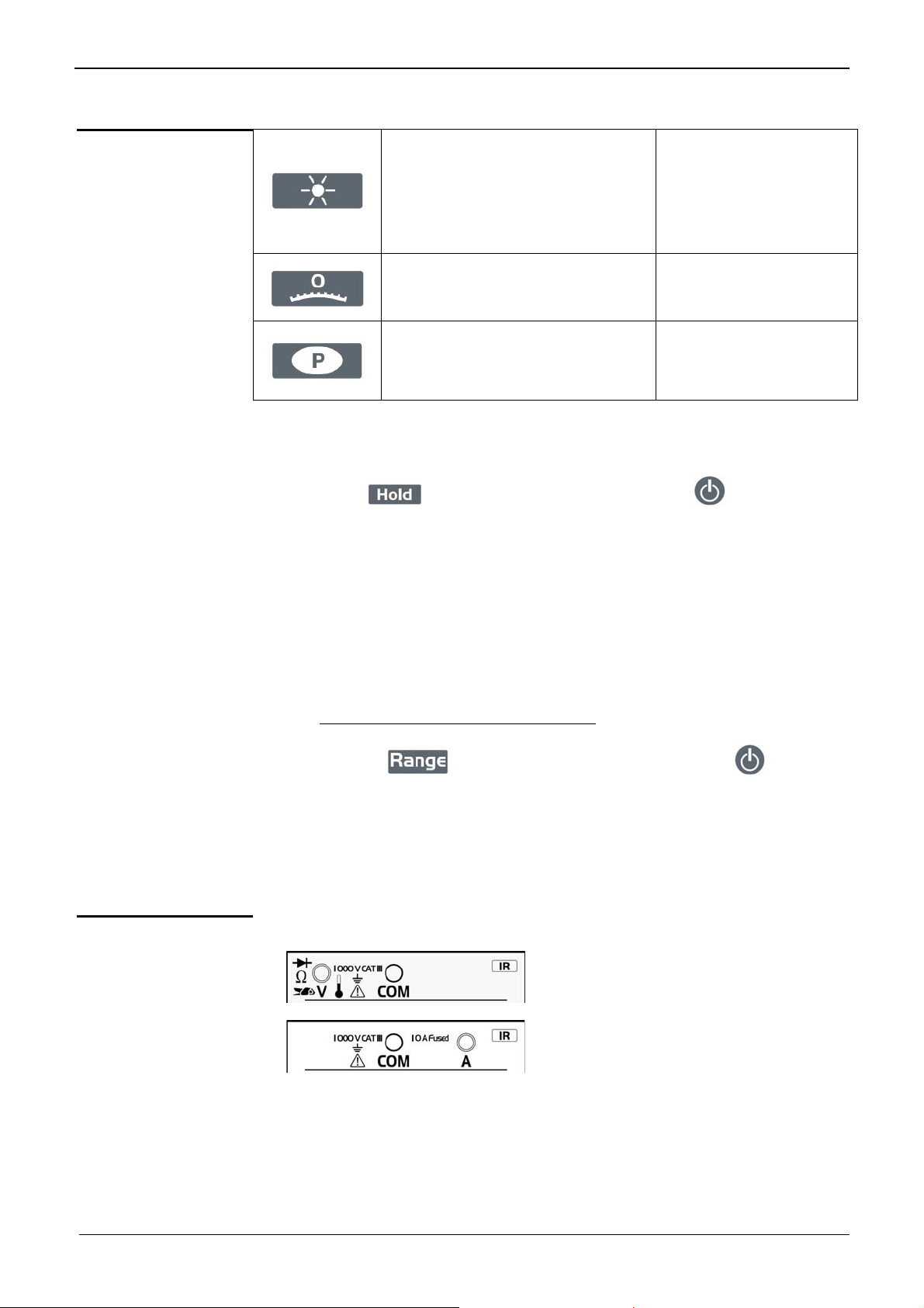
Activation of the Backlight:
- successive presses to increase the
brightness
- circular operation: brightness 1 Æ
brightness 2 Æ brightness 3
Æ brightness 1
Activation/Deactivation of the zero
centre bargraph:
MTX 3290 only
Activation/Deactivation of auto power
off:
MTX 3290 only
(sustained press)+press on ON/OFF Æ display of all
Deactivation of the
Backlight
Connection
in Volt
and other functions
in Ampere
• If, when you power up your multimeter
mode to recover the configuration when the multimeter was switched off,
press the
• After an automatic power down, the device restarts in USER mode.
The main display unit indicates, for 3s, the change to USER or BASIC mode.
key, hold it down, then press ON/OFF ( ).
, you want to activate the USER
* In the Volt and Ampere functions, the multimeter starts up in AC+DC, as
in the USER mode.
6,000- and 60,000-count digital multimeters 17
Page 18
Getting started
Getting started
Preparation for use
Instructions before
starting up
Power supply The devices operate with:
Powering up,
down
Power-up
configuration
When you use this multimeter, you must observe the usual safety rules,
which:
For your safety, use only the leads and accessories (clamp meter, etc.)
supplied with the instrument. Before each use, make sure that they are in
perfect condition.
The rechargeable batteries cannot be recharged in the multimeter.
Press ON/OFF
* Reminder: after replacing the batteries, wait 10s before powering
If the multimeter malfunctions, a long press (>2s) on this key can
In the Volt and Ampere functions, the instrument restarts in AC+DC.
• protect you from electrical hazards,
• protect the multimeter from operator errors.
• 4 1.5V alkaline batteries (LR6-AM3-AA) or
• 4 1.2V NI-MH rechargeable batteries of the same type.
to power up the device.
the device back up.
be applied to power down the instrument and then restore normal
operation.
In the BASIC mode, as default, the
device starts up in its elementary
configuration (default values) and in
Ac+DC function.
the V
MTX 3291 only: in the USER mode,
the device restarts in the
configuration and function selected
when it was powered down.
Automatic power
down
18 6,000- and 60,000-count digital multimeters
The multimeter automatically switches itself off after 30 minutes if there has
been no action on the front panel of the multimeter.
Auto power off is disabled:
• in the MAX, MIN, AVG, PEAK mode and in communication
• when the measured quantity (voltage, current) on the input exceeds
the danger thresholds, for the user's safety.
Page 19

Functional description
Functional description
* The examples described in this chapter use an
1. MAX MIN AVG mode A beep indicates an overshoot or a change of quantity.
unit
Measured signal: 230V, 50Hz:
Present value of the signal
Frequency of the signal
#
Displays in the
AC+DC function
V
Main display
Secondary display
unit
for the MAX value:
st
1
press on :
Present value of the signal
MAX value
The measured signal changes to 250V,
50Hz:
h: min: sec
MAX value
# Ex.: 27s
Momentary screen (4s) indicating the
time-stamped max. value, if the value
changes or if the value is looked up.
6,000- and 60,000-count digital multimeters 19
Page 20

Functional description
Functional description (continued)
for the MIN value:
# Ex.: 3s
The display then becomes:
nd
2
press :
Present value of the signal
MAX value
h: min: sec
MIN value
Momentary screen (4s) indicating the
time-stamped max. value, if the value
changes or if the value is looked up.
The display then becomes:
Present value of the signal
MIN value
20 6,000- and 60,000-count digital multimeters
Page 21

Functional description
Functional description (continued)
for the AVG value:
De-activation
rd
3
press on :
By a long press on the key.
Present value of the signal
AVG value
6,000- and 60,000-count digital multimeters 21
Page 22

Functional description
Functional description (continued)
2. PEAK mode A beep indicates an overshoot or a change of quantity.
#
Displays in the
AC+DC function
V
Measured signal: 250V, 50Hz:
Present value of the signal
Secondary measurement
for the Peak+ value:
for the Peak- value:
First press on :
Second press on :
Present value of the signal
Peak+ value
Present value of the signal
Peak- value
De-activation
By a long press on the key.
22 6,000- and 60,000-count digital multimeters
Page 23

Functional description
Functional description (continued)
3. ∆REL mode
#
Displays in the
AC+DC function
V
Activation of the
Δ
REL mode by
Short press on the key:
Measured signal: 1V, 100Hz:
Present value of the signal
Frequency of the signal
REL=(present value - reference value)
Reference value
The measured signal changes to1.5V:
(REL=1.5V- 1V=0.5V)
6,000- and 60,000-count digital multimeters 23
REL=(present value – reference value)
Reference value
Page 24

Functional description
Functional description (continued)
Short press, in the REL mode, on
:
Present value – reference value
REL (%) =
Reference value
Reference value
x100
A long press on the key
erases the reference value.
De-activation
By a long press on the key.
24 6,000- and 60,000-count digital multimeters
Page 25

Functional description
Functional description (continued)
4. "Clamp" function
# Ex.: 10mV/A
Present value of the signal
Transformation ratio, selected by
successive presses on
- press 1: 1mV/A
- press 2: 10mV/A
- press 3: 100mV/A
- press 4: 1,000mV/A
:
6,000- and 60,000-count digital multimeters 25
Page 26

Functional description
Functional description (continued)
Serial operation of the keys of the switch
MTX 3290
Press 1 Press 2 Press 3 Press 4 Press 5
V V V V V …3
Short
press
I I I I I …3
Pt100 Pt1000 Pt100 Pt1000 Pt100 …3
Capa Capa Capa Capa Capa …3
VLowZ VLowZ VLowZ VLowZ VlowZ …3
R=1 R=10 R=100 R=1000 R=1 …3
Continuity Diode Continuity …3
MTX 3291
Frequency Frequency Frequency Frequency Frequency …3
Press 1 Press 2 Press 3 Press 4 Press 5 Press 6
V dBm W V dBm W …3
I I I I I I …3
Pt100 Pt1000 Pt100 Pt1000 Pt100 Pt1000 …3
Capa Capa Capa Capa Capa Capa …3
VLowZ VLowZ VLowZ VLowZ VLowZ VLowZ …3
R=1 R=10 R=100 R=1000 R=1 R=10 …3
Short
press
Continuity Diode Continuity Diode …3
Frequency
- Pos. duty
cycle
- Neg. duty
cycle
- Width of
pos. pulse
- Width of
neg. pulse
Frequency …3
26 6,000- and 60,000-count digital multimeters
Page 27

Functional description
Functional description (continued)
Functions of the switch and keys
To access the
, , ,
W, continuity, diode, duty cycle, and pulse duration functions, press the button
of the switch corresponding to the chosen function.
Here are the possible combinations according to the type of measurement:
,
,
,
, ,dBm,
Type of measurement
Voltage VLowZ
Voltage V
Voltage V
Current A
AC, AAC+DC
AC
AC+DC
Voltage VDC
Current A
DC
Voltage 60mVDC
Voltage 60mVAC
Voltage 60mV
AC+DC
Temperature
Ohmmeter
Capacitance
MAX/MIN/
AVG
PEAK ±
9 9 9
9
9
-
-
9 9 9
9
9
9
-
-
-
RANGE
ΔREL
Auto. Manu.
in ΔREL
only
9 9 9
9 9
in ΔREL
only
9
-
-
9 9 9
9 9
9 9
9 9 9
9
-
9
9 9 9 9
in ΔREL
only
9
9
9 9
9 9
HOLD
-
-
-
-
-
Frequency
Period (1/F)
Continuity
Diode
dBm
W
Duty cycle
(DC+, DC-)
Pulse duration
(Pw+, Pw-)
9
9
- -
- -
- -
- -
- -
- -
-
-
9 9
9
- -
- -
- -
- -
- -
- -
-
9
9
9
9
9
9
9
-
-
9 9
9 9
- - -
-
-
-
-
-
9
9
9
9
9
-
-
-
-
-
6,000- and 60,000-count digital multimeters 27
Page 28

How are the various quantities measured?
How are the various quantities measured?
*
The connections illustrated in this chapter were made with an MTX 3290
multimeter (6,000 points). They would be the same with an MTX 3291 (60,000 pts).
1. Voltage measurement
superposed on a DC voltage, or DC voltage measurement at high
impedance.
installations. The input impedance <1M serves to avoid
measuring "phantom" voltages due to couplings between the lines.
In all cases, “O.L” is displayed above 1050V (MTX 3291) or 620V (MTX 3290)
and a beep sounds when the measurement exceeds 1000V (MTX 3291) or
600V (MTX 3290).
AC voltage measurement, or measurement of an AC voltage
:
This position is provided to allow measurements in electrical
:
1. Press:
2. Select AC+DC, AC or DC coupling of the signal by pressing
(the default coupling is AC+DC).
Depending on what you select, the screen displays DC, AC or AC+DC.
3. Connect the black lead to the “COM” terminal and the red lead to “V”.
or .
* If the connection is not correct, an audible beep and a visible signal
(LEADS) are activated.
4. Place the test probes on the terminals of the circuit to be measured:
5. Read the measurement value indicated on the display unit.
6. As default, the 2
nd
display unit indicates the frequency, except in DC.
* It is possible to activate the filter in VLowZ, VAC+DC, VAC. The cutoff
frequency of the filter is ≤300Hz.
When a voltage having a frequency above 150Hz is measured, it is
heavily attenuated, and so a large error may be observed. It is
necessary in this case to deactivate the filter to have the full passband.
28 6,000- and 60,000-count digital multimeters
Page 29

How are the various quantities measured?
How are the various quantities measured? (continued)
2. Current measurement
as an ammeter
1. Press:
2. Select the type of signal, AC+DC, AC, or DC, by pressing
on what you select, the screen displays AC, DC, or AC+DC.
3. Connect the black lead to the “COM” terminal and the red lead to “A”.
.
. Depending
* If the connection is not correct, an audible beep and a visible signal
(LEADS) are activated.
4. Place the test probes in series between the source and the load:
5. Read the measurement value indicated on the display unit.
“O.L” is displayed, if I >20A.
nd
6. As default, the 2
* It is possible to activate the filter in AAC+DC, AAC. The cutoff
frequency of the filter is ≤300Hz.
When a voltage having a frequency above 150Hz is measured, it is
heavily attenuated, and so a large error may be observed. It is
necessary in this case to deactivate the filter to have the full passband.
display unit indicates the frequency, except in DC.
6,000- and 60,000-count digital multimeters 29
Page 30

How are the various quantities measured?
How are the various quantities measured? (continued)
with a current
clamp
1. Press: .
2. Select the type of signal, AC+DC, AC, or DC, by pressing
Depending on what you select, the screen displays AC, DC, or AC+DC.
3. Connect the black lead of the clamp to the "COM" terminal and the red lead of
the clamp to "V".
4. Select the transformation ratio (the same as that of the clamp) - 1mV/A,
10mV/A, 100mV/A, or 1000mV/A - by pressing on "clamp" (
direct reading of the current.
5. Place the clamp around the conductor:
Clamp, V
.
) to have a
7. Read the measurement value indicated on the display unit. The
measurement accuracy is indicated in "Technical characteristics",
§. "Clamp" p. 46.
nd
8. As default, the 2
display unit indicates the transformation ratio in mV/A.
* It is possible to activate the filter in AAC+DC, AAC. The cutoff
frequency of the filter is ≤300Hz.
When a voltage having a frequency above 150Hz is measured, it is
heavily attenuated, and so a large error may be observed. It is
necessary in this case to deactivate the filter to have the full passband.
30 6,000- and 60,000-count digital multimeters
Page 31

How are the various quantities measured?
How are the various quantities measured? (continued)
3. Frequency measurement
1. Press:
2. Connect the black lead to the “COM” terminal and the red lead to “V”.
3. Place the test probes on the terminals of the circuit to be measured.
.
* Connect the instrument as for a resistance measurement.
4. Read the measurement value indicated on the display unit. The second
display unit indicates the period of the signal, 1/F.
4. Resistance measurement
5. Press
• positive duty cycle (DC+)
• negative duty cycle (DC-)
• positive pulse duration (Pw+)
• negative pulse duration (Pw-)
several times to obtain (MTX 3291 only):
* It is possible to activate the filter in AAC+DC, AAC. The cutoff
frequency of the filter is ≤300Hz.
1. Press the
2. Connect the black lead to the “COM” terminal and the red lead to “V”.
3. Place the test probes on the terminals of the component.
button of the switch.
* Resistance measurements must be made with power off. However,
while the presence of a voltage will prevent or throw off the
measurement, it will not damage the instrument.
4. Read the measurement value indicated on the display unit.
5. “O.L” is displayed, if the circuit is open.
6,000- and 60,000-count digital multimeters 31
Page 32

How are the various quantities measured?
How are the various quantities measured? (continued)
5. Audible continuity measurement
1. Press:
.
6. Diode test
2. Press
3. Connect the black lead to the “COM” terminal and the red lead to «V».
4. Place the test probes on the terminals of the circuit to be measured.
again; the "♪" symbol is displayed.
* Connect the instrument as for a resistance measurement.
5. Read the measurement value indicated on the display unit.
6. The continuity beep sounds when R <30 ±5.
7. “O.L” is displayed, if the circuit is open.
1. Press:
2. Press two times
3. Connect the black lead to the “COM” terminal and the red lead to “V”.
.
; the " " symbol is displayed.
4. Place the test probes on the terminals of the component:
5. Read the measured threshold voltage of the junction indicated
on the display unit.
If the value is <40mV ±10mV an audible signal is triggered.
6. “O.L” is displayed, if the circuit is open or the threshold of the diode >3V.
32 6,000- and 60,000-count digital multimeters
Page 33

How are the various quantities measured?
How are the various quantities measured? (continued)
7. Capacitance measurement
1. Press:
2. Connect the black lead to the “COM” terminal and the red lead to “V”.
3. Place the test probes on the terminals of the component:
.
4. Read the measurement value indicated on the display unit.
“O.L” is displayed, if the value to be measured exceeds the capacitance of
the range.
“O.L” is displayed, if the capacitor is short-circuited.
• For high values, the measurement cycle includes the display of "run" with
a "chaser" decimal point. This means that acquisition is in progress; wait
for the display of the digital result.
"Run" is displayed immediately, if the previous measurement
was in a small range.
• The prior discharge of very high capacitances helps shorten the
measurement time.
6,000- and 60,000-count digital multimeters 33
Page 34

How are the various quantities measured?
How are the various quantities measured? (continued)
8. Temperature measurement
1. Press:
.
2. Press
3. Press
display units.
to select the type of probe: Pt100 or Pt1000
to switch the temperature unit (°C or °F) between the two
* The unit displayed as default on the main display unit is °C.
4. Connect the adapter of the Pt100 or Pt1000 temperature probe (∗) to the
"COM" and "V" terminals, making sure that the polarity is correct:
sensor
5. Read the measurement value indicated on the display unit.
If "O.L" is displayed, the probe is open-circuit or short-circuited or the value to be
measured exceeds the range.
* For greater accuracy, avoid exposing the instrument to
sudden changes of temperature.
(∗) You will find a list of accessories in the CHAUVIN-ARNOUX catalogue.
34 6,000- and 60,000-count digital multimeters
Page 35

How are the various quantities measured?
How are the various quantities measured? (continued)
9. Measurement on an MLI type speed variator
Voltage
measurement
1. Press:
2. Select the type of signal, AC+DC, AC, or DC, by pressing
Depending on what you select, the screen displays AC, DC, or AC+DC.
3. Select the filter by pressing
4. Connect the black lead to the “COM” terminal and the red lead to “V”.
5. Place the test probes between two phases of the circuit to be measured:
.
.
.
6. Read the measurement values indicated on the display unit (voltage and
frequency):
In all cases, “O.L” is displayed above 1050V (MTX 3291) or 620V (MTX 3290)
and a beep sounds when the measurement exceeds 1000V (MTX 3291) or
600V (MTX 3290).
The presence of the symbol indicates that the 300Hz filter is active.
* It is very important to leave the filter activated to measure the voltage
and frequency of the signal without being perturbed by the MLI.
6,000- and 60,000-count digital multimeters 35
Page 36

How are the various quantities measured?
How are the various quantities measured? (continued)
Current
measurement
1. Press: .
2. Select the type of signal, AC+DC, AC, or DC, by pressing
Depending on what you select, the screen displays AC, DC, or AC+DC.
3. Select the filter by pressing
4. Connect the black lead to the “COM” terminal and the red lead to “A”.
5. Place the test probes in series between the source and the load:
.
.
6. Read the measurement value indicated on the display unit.
“O.L” is displayed, if I >20A.
The presence of the symbol indicates that the filter is active.
* It is very important to leave the filter activated to measure the voltage
and frequency of the signal without being perturbed by the MLI.
7. As default, the 2nd display unit indicates the frequency, except in DC.
* It is possible to make the current measurement using a current clamp
in conjunction with the multimeter (see §. 2. Current measurement
)
36 6,000- and 60,000-count digital multimeters
Page 37

How are the various quantities measured?
How are the various quantities measured? (continued)
10. Resistive power
(MTX 3291 only)
1. Press
three times.
2. Select AC+DC, AC or DC coupling of the signal by pressing
(the default coupling is AC+DC).
Depending on what you select, the screen displays DC, AC or AC+DC.
3. Connect the black lead to the “COM” terminal and the red lead to “V”.
4. Place the probes tips on the terminals of the resistive load:
5. As default, the main display unit indicates the power in W delivered to a
600 Ω resistive load (U²/600).
For a load
≠ 600
Ω
How to measure the
resistance
1. Start by applying power to the load.
2. Press
3. Press
power.
4. Press
5. Select AC+DC, AC or DC coupling of the signal by pressing
(the default coupling is AC+DC).
Depending on what you select, the screen displays DC, AC or AC+DC.
6. Apply power to the load.
7. Read the measurement value indicated on the display unit:
- the main display unit indicates the power in W (U
- the secondary display unit indicates the resistance measured on the
installation (600 Ohm by default).
. The display unit indicates the resistance.
to store the resistance, which will be used to calculate the
three times.
2
/R)
6,000- and 60,000-count digital multimeters 37
Page 38

How are the various quantities measured?
How are the various quantities measured? (continued)
11. dBm decibels in power (MTX3291, only)
1. Press:
.
2. Press
3. Press
4. Connect the black lead to the “COM” terminal and the red lead to “V”.
5. Place the test probes on the terminals of the circuit to be measured.
again.
to select the reference resistance, 50, 75, 90, or 600 Ohm.
* Connect the instrument as for a voltage measurement.
Reminder
6. Read the measurement value indicated on the display unit:
- the main display unit indicates the value in dBm
- the secondary display unit indicates the resistance measured on the
installation(50 Ω, by default).
R 0dBm (VRef) en
50 Ω
75 Ω
223.6mV
273.86mV
90 Ω
600 Ω
XdBm =
300mV
774.6mV
Vmeasured
20 Log
VRef
38 6,000- and 60,000-count digital multimeters
Page 39

SX-DMM software
SX-DMM software
SX-DMM: Processing software
Connection of the
isolated USB optical
lead supplied
These multimeters can be interfaced directly with a PC or other computer using
"SX-DMM" acquisition software:
The transmission rate is 9600 Bauds.
The transmission parameters are fixed (8 data bits, 1 stop bit, no parity).
1. Connect the isolated optical lead to the isolated optical input of the
multimeter (on the side of the multimeter). Mechanical polarization prevents
connection in reverse.
Connect the USB lead to one of the USB ports of the PC.
Install the USB driver on your PC (see the data sheet on the CD provided).
2.
USB
Isolated optical connector
Interface cable
Installing
the "SX-DMM"
software
1. Install the "SX-DMM" software on the PC using the CD.
2. Start the software for data acquisition and study the various display
possibilities (curves, tables, etc.).
* The symbol appears on the display unit when the instrument is
controlled from the PC (REMOTE mode).
For more information, refer to the "Help" menu of the software.
6,000- and 60,000-count digital multimeters 39
Page 40

Technical characteristics of the MTX 3290
Technical characteristics of the MTX 3290
Accuracy:
“n% L+n D” means
“n% of the reading
+ n Digit”
(see CEI 485)
Only values with tolerances or limits are guaranteed values.
Values without tolerances are given for guidance (standard NFC42670).
The technical specifications are guaranteed only after 30 minutes of warming up.
Except as otherwise indicated, they are valid from 10% to 100% of the measurement
range.
DC voltage In the "DC" mode, you measure a direct voltage or the DC component of an AC
voltage (filter activated).
Range
600mV 0 to 600.0mV 0.1mV 0.6% L+2D 10.9M
6V 0 to 6.000V 0.001V
60V 0 to 60.00V 0.01V 10.082M
600V (∗)
(∗) The display indicates "+OL" above +620V and "-OL" above - 620V. Protection:
850Vpk
Specified
measurement range
0 to 600.0V 0.1V 10.008M
Resolution
Intrinsic error Input impedance
0.3% L+2D
10.9M
Secondary measurements and displays: MAX, MIN, AVG
AC and AC+DC voltages
VAC RMS Protection: 850Vpk
With this function, the user can measure the true RMS (TRMS) value of an AC
voltage with its DC component (no capacitive coupling) or without its DC component.
Range
600mV
6V
60V
600V 2)
1) See the typical curve of the 300Hz filter.
2) The LCD indicates "+OL" above +620V, "-OL" below -620V or above 620VRMS.
Operating
range
0 to
600.0mV
0 to
6.000V
0 to
60.00V
0 to
600.0V
Specified
easurement
range 3)
60.0 to
600.0mV
0.600 to
6.000V
6.00 to
60.00V
60.0 to
600.0V
Resolution
0.1mV
0.001V
0.01V 10.082 M
0.1V 10.008 M
Uncertainty
(±)
2% L+
0.25%x
[F(kHz)-1]L
±5D
2% L+
0.18%x
[F(kHz)-1]L
±3D
Additional
uncertainty F
(Hz) 1)
45<F<65Hz
0.3% L
typ.
at 100Hz
0 .7% L
typ.
at 150Hz
1.8% L
typ.
at 300Hz
30% L
typ.
Pass
band
10Hz to
20kHz
10Hz to
20kHz
@ 1kHz
Input
impedance
// <50 pF
10.9 M
10.9 M
Peak
factor
3 to
500mV
3 to 5V
3 to 50V
3 to
500V
3) From 1kHz, the measurement must exceed 15% of the range.
Secondary measurements and displays: FREQ (AC coupling), MAX, MIN, AVG,
PEAK
40 6,000- and 60,000-count digital multimeters
Page 41

Technical characteristics of the MTX 3290
m
Technical characteristics of the MTX 3290 (continued)
VAC+DC TRMS Protection: 850Vpk
Range
Operating
range
Specified
measure.
range 3)
Resolution
Uncertainty
DC (±)
Uncertainty
AC (±)
Additional
uncertainty
F (Hz) 1)
Pass
band
Input
impedance
// <50 pF
Peak
factor
600mV
6V
60V
600V 2)
0 to
600.0mV
0 to
6.000V
0 to
60.00V
0 to
600.0V
1) See the typical curve of the 300Hz filter.
2) The LCD indicates “+OL” above +620V, “-OL” below -620V or above 620VRMS.
3) From 1kHz, the measurement must exceed 15% of the range.
Secondary measurements and displays: FREQ (AC coupling),MAX,MIN,AVG,PEAK
LowZ AC Protection: 850Vpk
V
The pass band is reduced to 300Hz if the filter is activated. The frequency
measurement is made like the measurement in a 300Hz pass band.
Range
Operating
range
60.0 to
600.0mV
0.600 to
6.000V
6.00 to
60.00V
60.0 to
600.0V
2% L
0.1mV
0.001V
0.01V 10.082M
0.1V 10.008M
Specified
easurement
range 3)
0.8% L
±10D
Resolution
+ 0.18%x
[F(kHz)-1]L
±5D
2% L
+ 0.18%x
[F(kHz)-1]L
±3D
Uncertainty (±)
45<F<65Hz
0.3% L
typ.
at 100Hz
0 .7% L
typ.
at 150Hz
1.8% L
typ.
at 300Hz
30% L
typ.
Additional
uncertainty F
(Hz) 1)
10Hz
to
20kHz
10Hz
to
20kHz
Input
impedance
//<50 pF
10.9M
10.9M
3 to
500mV
3 to
5V
3 to
50V
3 to
500V
Peak
factor
600mV
6V 0 to 6.000V
60V 0 to 60.00V
600V 2) 0 to 600.0V
0 to
600.0mV
60.0 to
600.0mV
0.600 to
6.000V
6.00 to
60.00V
60.0 to
600.0V
2 .2% L+
0.1mV
0.001V
0.01V
0.1V 3 to 500V
0.25%x
[F(kHz)-1]L
±5D
2 .2% L+
0.18%x
[F(kHz)-1]L
±3D
45<F<65Hz
0.3% L typ.
at 100Hz
0.7% L typ.
at 150Hz
1.8% L typ.
at 300Hz
30% L typ.
3 to
500mV
3 to 5V
≅300k
3 to 50V
1) See the typical curve of the 300Hz filter.
2) The LCD indicates “+OL” above +620V, “-OL” below -620V or above 620VRMS.
3) From 1kHz, the measurement must exceed 15% of the range.
Secondary measurements and displays: FREQ (AC coupling), MAX, MIN, AVG,PEAK
6,000- and 60,000-count digital multimeters 41
Page 42

Technical characteristics of the MTX 3290
t
Technical characteristics of the MTX 3290 (continued)
Currents
DC current
Three possible modes: DC, AC, AC+DC
In DC mode, you can measure a direct current or the DC component of an
alternating current.
In the AC and AC+DC modes, you can measure the true RMS (TRMS) value of
an alternating current with/without its direct component (no capacitive coupling in
"DC" mode).
Particular reference conditions
6mA range
: Measuring a strong current for a long time can cause a temperature
:
rise in some components. In this case, it is necessary to wait some time for the
metrological characteristics specified in 6mA to be restored.
Range
6mA 0 to 6.000mA 0.002 to
60mA 0 to 60.00mA
600mA 0 to 600.0mA 0.2 to 600.0mA 0.1mA 1.2% L ± 2D 0.58mV/mA
6A 0 to 6.000A 0.200 to 6.000A 0.001A 1.2% L ± 3D 0.05V/A
10 A/20A
(∗)
Operating
range
0 to 20.00A 0.20 to 20.00A 0.01A 1.2% L ± 2D
Specified
measurement
range
6.000mA
.02 to 60.00mA 0.01mA 1.2% L ± 2D 3mV/mA
Resolution
1µA 1.2% L ± 5D
Uncertainty
(±)
Voltage
drop
25mV/mA
0.05V/A
Protection
Fuse
10A/600V
>50kA
AAC RMS current
The display indicates "OL" above 19.99A. The symbol blinks and a beep
sounds above 10A.
(∗) Acceptable overload: 10A to 15A for 30s max. with a pause of 5min between
2 measurements. Ambient temp. 35°C max.
Secondary measurements and displays: MAX, MIN, AVG
Range
6mA
60mA
600mA
6A
10A/20A
(∗)
The display indicates "OL" above 19.99A. The symbol blinks and a beep
Operating
range
0 to
6.000mA
0 to
60.00mA
0 to
600.0mA
0 to
6.000A
0 to
20.00A
Specified
easuremen
range
0.600 to
6.000mA
6.00 to
60.00mA
60.0 to
600.0mA
0.600 to
6.000A
1.00 to
10.00A
Resolution
1µA 1.7% L ± 5D
0.01mA
0.1mA
0.001A 1.7% L ± 5D 2.8 to 5A 0.05V/mA
0.01A 1.5% L ± 3D 3.7 to 8A 0.05V/mA
Uncertainty (±)
40Hz to 20kHz
(**)
1.5% L ± 3D
Peak factor
2.6 to
5mA
2.6 to
50mA
2.6 to
500mA
Voltage
drop
25mV/mA
3mV/mA
0.58mV/mA
Protection
Fuse
10A/600V
>50kA
sounds above 10A.
Secondary measurements and displays: FREQ (AC coupling) MAX, MIN, AVG,
PEAK
(∗) Acceptable overload: 10A to 15A for 30s max. with a pause of 5min between 2
measurements. Ambient temp. 35°C max.
(∗∗) Additional uncertainty with the 300Hz filter.
42 6,000- and 60,000-count digital multimeters
Page 43

Technical characteristics of the MTX 3290
Technical characteristics of the MTX 3290 (continued)
AAC+DC TRMS current Warning: The sum AC+DC must never exceed the range, 600mA, or
60mA, or 6mA, or 6A, or 10A, as the case may be.
Range
Operating
range
Specified
measure-
ment range
esolution
Uncertainty AC
40Hz at 20kHz
(±) (∗∗)
Additional
uncertainty
DC (±)
Peak
factor
Voltage
drop
Protection
6mA
60mA
600mA
6A
10A
/20A*
The display indicates “OL” above 19.99A. The symbol blinks and a beep
0 to
6.000mA
0 to
60.00mA
0 to
600.0mA
0 to
6.000A
0 to
20.00A
0.060 to
6.000mA
6.00 to
60.00mA
60.0 to
600.0mA
0.600A to
6.000A
0.60A to
20.00A
0.01mA
0.1mA
0.001A
0.01A
1µA
1.7% L +[0.08%x
(FkHz-1)] L
±5D
1.5% L +[0.08%x
(FkHz-1)] L
±3D
1.7% L+[0.08%x
(FkHz-1)] L
±5D
1.5% L+ [0.08%x
(FkHz-1)] L
±3D
±15D
±13D
±10D 2.8 to 5A 0.05V/mA
±10D 3.7 to 8A 0.05V/mA
2.6 to
5mA
2.6 to
50mA
2.6 to
500mA
25mV/mA
3mV/mA
0.58mV/mA
Fuse
10A/600V
>50kA
sounds above 10A.
(*) Acceptable overload: 10A to 15A for 30s max. with a pause of 5min between 2
measurements. Ambient temp. 35°C max.
Secondary measurements and displays: F (AC coupling), MAX, MIN, AVG, PEAK
(**) Additional uncertainty with the 300Hz filter.
6,000- and 60,000-count digital multimeters 43
Page 44

Technical characteristics of the MTX 3290
Technical characteristics of the MTX 3290 (continued)
Frequency
Main frequency
measurement
In this setting, you can measure the frequency of a voltage.
Particular reference conditions
: 150mV <U <600V
When the switch is set to Hz, the 300Hz filter is not in service.
Protection: 850Vpk
Range Operating range
60Hz 10.00 to 60.00Hz 10.00 to 60.00Hz 0.01Hz
600Hz 10.0 to 600.0Hz 10.00 to 600.0Hz 0.1Hz
6kHz 0 to 6.000kHz 0.010 to 6.000kHz 0.001kHz
60kHz 0 to 60.00kHz 0.01 to 60.00kHz 0.01kHz
600kHz 0 to 200.0kHz 0.1 to 200.00kHz 0.1kHz
Specified
measurement
range
Resolution Intrinsic error
0.1% L ±1D
Below 10Hz, or if the signal detection level is inadequate, the reading is forced to
zero.
* The measured period in ms is available on the second display unit.
Secondary
frequency
measurement
You can measure the frequency and magnitude of a voltage or of a current
simultaneously.
Same accuracy as in the "Hz" setting
Particular reference conditions
: 150mV <U <600V
0.15A <I <10A
Max. frequency measurable in volts: 20kHz
Max. frequency measurable in amperes: 20kHz
When the switch is set to VLowZ, Volts or Ampere, if the 300Hz filter is activated,
the measurable frequency remains within the limits of the PB of the filter.
Below 10Hz, or if the signal detection level is inadequate, the reading is forced to
“-----“.
44 6,000- and 60,000-count digital multimeters
Page 45

Technical characteristics of the MTX 3290
Technical characteristics of the MTX 3290 (continued)
Resistance
Ohmmeter In this setting, the user can measure a resistance.
Capacitance
Particular reference conditions
:
The (+COM) input must not have been overloaded following the accidental
application of a voltage to the input terminals with the switch set to or T°.
If this happens, the return to normal may take about ten minutes.
Protection: 850Vpk
Range
600
6k 0 to 6.000k 0.001k
60k 0 to 60.00k 0.01k 12.6A
600k 0 to 600.0k 0.1k 1.26A
6M 0 to 6.000M 0.001M 1.5% L ±3D 240nA
60MΩ
Specified
measurement
range
0 to 600.0 ∗
0 to 60.00M
Resolution Uncertainty
0.1 0.5% L ±2D 850µA
0.5% L ±2D
0.01M 3% L ±3D 29nA
Measurement
current
126.6A
(∗) REL measurements
Open-circuit
voltage
<5V
Capacitance
meter
In this setting, the user can measure the capacitance of a capacitor.
Range
6nF
60nF 0 to 60.00nF 0 to 60.00nF 0.01nF 1.5% L ±8D 1.26µA 400ms
600nF 0 to 600.0nF 0 to 600.0nF 0.1nF 1.5% L ±5D 1.26µA 400ms
6µF 0 to 6.000µF 0 to 6.000µF 0.001µF 1.5% L ±5D 12.6µA 0.125 s/µF
60µF 0 to 60.00µF 0 to 60.00µF 0.01µF 1.5% L ±5D 126.6µA 0.125 s/µF
600µF 0 to 600.0µF 0 to 600.0µF 0.1µF 3.5% L ±5D 850µa 0.125 s/µF
6mF 0 to 6.000mF 0 to 6.000mF 1µF 4.5% L ±5D 850µa 17 s/mF
60mF 0 to 60.00mF 0 to 60.00mF 10µF 6.5% L ±5D 850µa 17 s/mF
Operating
range
0.100 to
6.000nF
Specified
measurement
range
0.100 to
6.000nF
Resolution
0.001nF 2.5% L ±30D 1.26µA 400ms
Intrinsic
error
Measurement
current
Measurement
The use of wires that are very short and shielded is strongly recommended.
time
Protection: 850Vpk
6,000- and 60,000-count digital multimeters 45
Page 46

Technical characteristics of the MTX 3290
Technical characteristics of the MTX 3290 (continued)
Diode Test
Audible continuity
Clamp
DC current
Range Resolution Accuracy Open-circuit voltage
3V 1mV 2% L ±3D <5V <1.1mA
Measurement
current
Audible signal triggered if <40mV ±10mV
Protection: 850Vpk
Range Resolution Accuracy
600 0.1 0.5% L ±3D <5V <1.1mA 850Vpk
Open-circuit
voltage
Measurement
current
Protection
Response time <100ms
Triggering threshold: <30 ±5
Protection: 850Vpk
You can measure a current using various current clamps and obtain a direct
reading of the current by selecting the correct transformation ratio, which must be
the same as that of the clamp.
If the signal detection level is insufficient, the value is forced to "-----"
The input impedance is approximately 10M.
* Add the error of the clamp to the intrinsic error of the multimeter, specified
in the tables below.
Range
Ratio
1mV/A
10mV/A
100mV/A
1000mV/A
600mA 6A 60A 600A 6000A
Resolution
Accuracy 0.6%L ±2D 0.6%L ±2D 0.3%L ±2D
Resolution
Accuracy 0.6%L ±2D 0.6%L ±2D 0.3%L ±2D
Resolution 0.1mA 0.001A 0.01A
Accuracy 0.6%L ±2D 0.6%L ±2D 0.3%L ±2D
Resolution 0.1mA 0.001A
Accuracy 0.6%L ±2D 0.3%L ±2D
0.001A 0.01A 0.1A
0.01A 0.1A 1A
Secondary measurements and displays: MAX, MIN, AVG and transformation ratio of
the sensor
AAC RMS current
Range
Ratio
1mV/A
10mV/A
100mV/A
1000mV/A
600mA 6A 60A 600A 6000A
Resolution
Accuracy
Resolution
Accuracy
Resolution 0.1mA 0.001A 0.01A
Accuracy
Resolution 0.1mA 0.001A
Accuracy 2% L ±5D 2% L ±3D
Peak factor 3 @ 500mA @ 5A @ 50A @ 500A @ 5000A
2% L ±5D (∗)
0.001A 0.01A 0.1A
2% L ±5D (∗)
2% L ±5D 2% L ±3D
0.01A 0.1A 1A
2% L ±5D (∗)
2% L ±5D 2% L ±3D
2% L ±5D 2% L ±3D
Secondary measurements and displays: MAX, MIN, AVG and transformation ratio
of the sensor
300Hz filter: if the filter is active, see "300Hz filter" curve for the additional
uncertainty. (∗) : see "Frequency response" curve, p. 47.
46 6,000- and 60,000-count digital multimeters
Page 47

Technical characteristics of the MTX 3290
Technical characteristics of the MTX 3290 (continued)
AAC+DC TRMS current
Range
Ratio
1mV/A
10mV/A
100mV/A
1000mV/A
600mA 6A 60A 600A 6000A
Resolution
Accuracy
Resolution
Accuracy
Resolution 0.1mA 0.001A 0.01A
Accuracy
Resolution 0.1mA 0.001A
Accuracy
Peak factor 3 @ 500mA @ 5A @ 50A @ 500A @ 5000A
2.8% L ±15D
(∗)
2.8% L ±15D 2.8% L ±13D
0.001A 0.01A 0.1A
2.8% L ±15D
(∗)
2.8% L ±15D 2.8% L ±13D
0.01A 0.1A 1A
2.8% L ±15D
(∗)
2.8% L ±15D 2.8% L ±13D
2.8% L ±15D 2.8% L ±13D
Secondary measurements and displays: MAX, MIN, AVG and transformation ratio
of the sensor
300Hz filter: if the filter is active, see “300Hz filter” curve for the additional
uncertainty.
Frequency
response
(∗): see “Frequency response” curve, below.
6,000- and 60,000-count digital multimeters 47
Page 48

Technical characteristics of the MTX 3290
Technical characteristics of the MTX 3290 (continued)
Temperature
Pt100/Pt1000
Peak
SURV
MIN, MAX, AVG
The user can measure the temperature by means of a Pt100/Pt1000 sensor.
Range Measurement current Resolution Accuracy Protection
- 125°C to
+ 75°C
- 200°C to
+ 800°C
<1mA (Pt100)
<0.1mA (Pt1000)
<1mA (Pt100)
<0.1mA (Pt1000)
0.1°C
---
0.1°C
---
± 0.5°C
850Vpk
0.1% L ± 1°C
0.07% L ± 1°C
"Active" protection by PTC thermistor
Display in °C/°F possible
Add 1% L ± 30 D to obtain the accuracy corresponding to the function and the
range.
Fmax 1kHz (1ms)
Protection 850Vpk
θ
T
θ=1ms mini
Add 0.2% L + 2D to obtain the accuracy corresponding to the function and the
range.
Acquisition time of the extrema approximately 100ms.
Protection 850Vpk
Operation of the audible beep
Beep reporting a valid key
Beep reporting an invalid key
Successive beeps reporting an overshoot of the danger
threshold (alarm)
Successive beeps reporting recording of the MAX, MIN, PEAK
Successive beeps (alarm) Æ current >10A
Continuity measurement
High-pitched
sound
Low-pitched
sound
High-pitched
sound
High-pitched
sound
High-pitched
sound
Mediumpitched sound
48 6,000- and 60,000-count digital multimeters
Page 49

Technical characteristics of the MTX 3290
Technical characteristics of the MTX 3290 (continued)
Variation in the nominal range of use
Quantity of
influence
Battery
voltage
Temperature
Humidity
(without
condensation)
Common mode
Range of
influence
4V to 6V all
VACmV, V
VAC, VAC+DC,V
AAC and AAC+DC 0.08% L ±0.1D/1°C 0.12% L ±0.1D/1°C
-10°C… 18
28 ... 55°C
Stabilization time
10% ... 80% RH
600V
50Hz
VAC, VAC+DC, V
Quantity
influenced
VDCmV 0.02% L ±0.2D/1°C 0.04% L ±0.25D/1°C
mV 0.08% L ±0.2D/1°C 0.15% L ±0.25D/1°C
LowZ
VDC 0.01% L ±0.1D/1°C 0.05% L ±0.1D/1°C
0.25% L ±0.1D/1°C
LowZ
ADC 0.05% L ±0.1D/1°C 0.1% L ±0.1D/1°C
Ω
60 MΩ
µF 0.2% L ±0.1D/1°C
mF 0.6% L ±0.1D/1°C
Hz 0.01% L/1°C
Temperature
V
A
Ω
Hz
LowZ
typical MAX
< 3D
0.01% L ±0.1D/1°C 0.1% L/1°C
0.05% L/1°C 0.1% L/1°C
≈ 2 h
Range typical
60mV,
600mV
6V >60dB
60V,
600V,
1000V
Influence
0.2% L+1D
0.3% L/1°C
± 2°C+0.05% L/1°C
2.5 h
0 0
>35dB
>95dB
Response of the 300Hz filter
-10,00
-20,00
-30,00
Atténuation (%)
-40,00
-50,00
-60,00
Fr
equency (Hz)
0 50 100 150 200 250 300 350 400 450
0,00
Attenuation (%)
6,000- and 60,000-count digital multimeters 49
Page 50

Technical characteristics of the MTX 3291
V
Technical characteristics of the MTX 3291
“n%L + nD” means
“n% of the reading
(see CEI 485)
DC voltage
Accuracy:
+ n Digit”
Only values with tolerances or limits are guaranteed values.
Values without tolerances are given for guidance (standard NFC42670).
The technical specifications are guaranteed only after 30 minutes of warming up. Except
as otherwise indicated, they are valid from 10% to 100% of the measurement range.
In the “DC” mode, you measure a direct voltage or the DC component of an AC voltage
(filter activated).
60mV range: Measuring a strong current or measuring a current for a long time may
cause a temperature rise of some components.
Protection: 1414 Vpk
Range
60mV 1) 0 to 60.000mV 0.001mV 0.5% L+35D
600mV 0 to 600.00mV 0.01mV 0.5% L+25D
6V 0 to 6.0000V 0.0001V
60V 0 to 60.000V 0.001V
600V 0 to 600.00V 0.01V
Specified
measurement range
Resolution Intrinsic error
0.05% L+25D
Input impedance
10.612M
10.9M
10.9M
10.082M
10.008M
AC and AC+DC voltages
VAC RMS
1000V 2) 0 to 1000.0V 0.1V 0.07% L+25D
10.008M
1) This range is accessible only with the Range key.
Input impedance: approx. 10.6M // 50 pF
2) The display indicates "+OL" above +1050V and "-OL" below -1050V.
Secondary measurements and displays: MAX, MIN, AVG
With this function, the user can measure the true RMS (TRMS) value of an AC voltage
with its DC component (no capacitive coupling) or without its DC component.
60mV range: Measuring a strong current or measuring a current for a long time may
cause a temperature rise of some components.
Protection: 1414 Vpk
2)
3)
Operating
60.000mV
600.00mV
6.0000V
60.000V
1000.0V
Range
60mV
600mV
6V
60V
600V 0 to 600.00
1000V
range
0 to
0 to
0 to
0 to
0 to
Specified
measurem.
range 4)
6.000 to
60.000mV
60.00 to
600.00mV
0.6 to
6.0000V
6.000 to
60.000V
60.00 to
600.00V
60 to
1000.0V
Resolution
0.001mV
0.01mV
0.0001V
0.001V 10.082 M
0.01V 10.008 M
0.1V 10.008 M
Uncertainty (±)
1.5% L
± 35D
L
1%
+ 0.25%x
[F(kHz)-1] L
± 30D
0.5% L
+ 0.18%x
[F(kHz)-1] L
± 25D
Additional
uncertainty
F(Hz) 1)
45<F<65Hz
0.3% L typ.
at 100Hz
0.7% L typ.
at 150Hz
1.8% L typ.
at 300Hz
30% L typ.
Pass band
400Hz 10.612 M
10Hz to
50kHz
( 23%
@100kHz)
10Hz to
100kHz
@ 1kHz
Input
impedance
//<50 pF
10.9 M
10.9 M
1000.0V
Peak
factor
3 to
50.0mV
3 to
500.0mV
3 to
5.0V
3 to
50.0V
3 to
500.0V
1.42 to
50 6,000- and 60,000-count digital multimeters
Page 51

Technical characteristics of the MTX 3291
6
Technical characteristics of the MTX 3291 (continued)
AC RMS
V
(continued)
VLowZ AC RMS
Protection: 1414 Vpk
1) See the typical curve of the 300Hz.
2) This range is accessible only with the Range key
Input impedance: approx. 10.6M // 50 pF
3) The LCD indicates “+OL” above +1050V, “-OL” below -1050V or above 1050VRMS.
4) From 1kHz, the measurement must exceed 15% of the range.
Secondary measurements and displays: FREQ (AC coupling), MAX, MIN, AVG, PEAK
The pass band (between 3dB down points) is reduced to 300Hz, if the filter is activated. In
VLowZ, there is no 60mV range.
The frequency measurement is made like the measurement in a 300Hz pass band.
Range
600mV
6V
60V
Operating
range
0 to
600.00mV
0 to
6.0000V
0 to
60.000V
600V 0 to 600.00V
Specified
measurement
range 3)
60.00 to
600.00mV
0.6 to
6.0000V
6.000 to
60.000V
60.00 to
600.00V
Resolution
Uncertainty (±)
1% L+ 0.25%x
0.01mV
[F(kHz)-1] L
± 30D
0.0001V
0.001V 3 to 50.0V
0.5% L+
0.18%x
[F(kHz) -1] L
0.01V 3 to 500.0V
± 25D
Additional
uncertainty
F(Hz) 1)
45<F<65Hz
0.3% L typ.
at 100Hz
0.7% L typ.
at 150Hz
1.8% L typ.
at 300Hz
30% L typ.
Pass band
≅ 300 k
Input
impedance
//<50 pF
3 to
500.0mV
3 to 5.0V
VAC+DC TRMS
Protection: 1414 Vpk
2)
1000V
1) See the typical curve of the 300Hz.
2) The LCD indicates “+OL” above +1050V, “-OL” below -1050V or above 1050VRMS.
0 to
1000.0V
60 to
1000.0V
0.1V
1.42 to
1000.0V
3) From 1kHz, the measurement must exceed 15% of the range.
Secondary measurements and displays: FREQ (AC coupling), MAX, MIN, AVG, PEAK
60mV range: Measuring a strong current or measuring a current for a long time may cause a
temperature rise of some components.
Range
60mV 2)
600mV
6V
60V
600V
Operating
range
0 to
60.000mV
0 to
00.00mV
0 to
6.0000V
0 to
60.000V
0 to
600.00V
Specified
measurem.
range 4)
6.000 to
60.000mV
60.00 to
600.00mV
0.6 to
6.0000V
6.000 to
60.000V
60.00 to
600.00V
Resolution
0.001mV
0.01mV
0.0001V
0.001V
0.01V
Additional
uncertainty
DC (±)
± 15D
Uncertainty
AC (±)
1.5% L
±35D
0.8% L
+ 0.18%x
[F(kHz)-1] L
±30D
0.5% L
+ 0.18%x
[F(kHz)-1] L
±25D
Additional
uncertainty
F(Hz) 1)
45<F<65Hz
0.3% L typ.
at 100Hz
0.7% L typ.
at 150Hz
1.8% L typ.
at 300Hz
30% L typ.
Pass band
≈ 400Hz
10Hz to
50kHz
10Hz to
100kHz
Input
impedance
//<50 pF
10.612 M
10.9 M
10.9 M
10.082 M
10.008M
Peak factor
500mV
3 to 5V
3 to
50mV
3 to
3 to
50V
3 to
500V
0 to
3)
1000V
1) See the typical curve of the 300Hz.
2) This range is accessible only with the Range key - Input impedance: approx. 10.6M//50 pF
1000.0V
60 to
1000.0V
0.1V
10.008 M
1.42 to
1000V
3) The LCD indicates “+OL” above +1050V, “-OL” below -1050V or above 1050VRMS.
4) From 1kHz, the measurement must exceed 15% of the range.
Secondary measurements and displays: FREQ (AC coupling), MAX, MIN, AVG, PEAK
6,000- and 60,000-count digital multimeters 51
Page 52

Technical characteristics of the MTX 3291
Technical characteristics of the MTX 3291 (continued)
Currents
DC current
Three possible modes: DC, AC, AC+DC
In DC mode, you can measure a direct current or the DC component of an
alternating current.
In the AC and AC+DC modes, you can measure the true RMS (TRMS) value of
an alternating current with/without its direct component (no capacitive coupling in
"DC" mode).
Particular reference conditions:
600µA and 6mA ranges
: Measuring a strong current for a long time may cause a
temperature rise of some components. In this case, it is necessary to wait some
time for the metrological characteristics specified in these ranges.
Range
600µA
6mA
60mA
600mA
Operating
range
0 to
600.00µA
0 to
6000.0mA
0 to
60.000mA
0 to
600.00mA
Specified
measurement
range
0.02 to
600.00µA
0.002 to
6.0000mA
0.020 to
60.000mA
0.20 to
600.00mA
Resolution
0.01µA 1% L ±25D 10mV/mA
0.1µA 0.8% L ±25D 25mV/mA
0.001mA 0.8% L ±20D 3mV/mA
0.01mA 0.8% L ±20D 0.58mV/mA
Uncertainty
(±)
Voltage drop Protection
Fuse
11A/1000V
>20kA
6A
10A/20A
(∗)
The display indicates “OL” above 19.99A. The
0 to
6.0000A
0 to
20.000A
0.2000 to
6.0000A
0.200 to
20.000A
0.0001A 0.8% L ±20D 0.05V/A
0.001A 0.8% L ±20D 0.05V/A
symbol blinks and a beep
sounds above 10A.
(∗) Acceptable overload: 10A to 20A for 30s max. with a pause of 5min between 2
measurements. Ambient temp. 35°C max.
Secondary measurements and displays: MAX, MIN, AVG
52 6,000- and 60,000-count digital multimeters
Page 53

Technical characteristics of the MTX 3291
K
Technical characteristics of the MTX 3291 (continued)
AAC RMS current
Range Operating range
600µA
6.000mA
60mA
600mA
6A
10A/20A
(∗)
The display indicates “OL” above 19.99A. The
0 to
600.00µA
0 to
6.0000mA
0 to
60.000mA
0 to
600.00mA
0 to
6.0000A
0 to
20.000A
Specified
measurement
range
60 to
600.00µA
0.6000 to
6.0000mA
6.000 to
60.000mA
60.00 to
600.00mA
0.6000 to
6.000A
1.000 to
20.000A
Resolution
0.01µA
0.1µA
0.001mA
0.01mA
0.0001A
0.001A
Uncertainty (±)
40Hz to 20kHz
(**)
1.5% L
±30D
1.2% L+[0.08%
x (FkHz-1)] L
±25D
1% L+[0.08%
x (FkHz-1)] L
±25D
1% L +[0.1%
x (FkHz-1)] L
±25D
1.2% L+ [0.1%
x (FkHz-1)] L
±25D
symbol blinks and a beep
Peak factor
2.6 to
500µA
2.6 to
5mA
2.6 to
50mA
2.6 to
500mA
Voltage
drop
10mV/µA
25mV/mA
3mV/mA
0.58mV/mA
2.8 to 5A 0.05V/mA
3.7 to 8A 0.05V/mA
Protection
Fuse
/1000V
>20kA
sounds above 10A.
Secondary measurements and displays: FREQ (AC coupling), MAX, MIN, AVG,
PEAK
(∗) Acceptable overload: 10A to 20A for 30s max. with a pause of 5min between 2
measurements. Ambient temp. 35°C max.
(∗∗) Additional uncertainty with the 300Hz filter.
11A
AAC+DC TRMS current Warning: the sum AC+DC must never exceed the range, 600mA, or
60mA, or 6mA, or 600µA or 6A, or 10A, as the case may be.
The AC component must represent at least 5% of the amplitude of the AC+DC total
for it to be possible to measure it.
Range
600µA
6mA
60mA
600mA
6A
10A/20A
The display indicates “OL” above 19.99A. The
(∗)
Operating
range
0 to
600.00µA
0 to
6.0000µA
0 to
60.00mA
0 to
600.00mA
0 to
6.0000A
0 to
20.00A
Specified
measurement
range
60 to
600.00µA
0.6000 to
6.0000mA
6.000 to
60.000mA
60.00 to
600.00mA
0.6000 to
6.000A
0.600 to
20.000A
Resolution
0.01µA
0.1µA
0.001mA
0.01mA
0.0001A
0.001A
Uncertainty (±)
40Hz to 20kHz
(**)
1.5% L
±20D
1% L +[0.08% x
(FkHz - 1)]L
±25D
1% L +[0.08%x
(FkHz - 1)]L
±25D
1% L+[0.1%x
(FkHz-1)]L
±25D
1.2% L+ [0.1%x
(FkHz-1)]L
±25D
Peak
factor
Voltage
drop
±20D
±15D
2.6 to
500µA
2.6 to 5mA 25mV /mA
2.6 to
50mA
2.6 to
500mA
2.8 to 5A 0.05V /mA
3.7 to 8A 0.05V /mA
symbol blinks and a beep sounds
above 10A.
(∗) Acceptable overload: 10A to 20A for 30s max. with a pause of 5min between 2
measurements. Ambient temp. 35°C max.
Secondary measurements and displays: FREQ (AC coupling), MAX, MIN, AVG, PEA
(∗∗) Additional uncertainty with the 300Hz filter.
Protection Range
10mV/µA
3mV/mA
0.58mV/m
A
Fuse
11A/1000
V
>20kA
6,000- and 60,000-count digital multimeters 53
Page 54

Technical characteristics of the MTX 3291
Technical characteristics of the MTX 3291 (continued)
Frequency
Main frequency
measurement
Secondary
frequency
measurement
In this setting, you can measure the frequency of a voltage.
Particular reference conditions
: 150mV <U <600V
When the switch is set to Hz, the 300Hz filter is not in service.
Protection: 1414 Vpk
Range Operating range
60Hz 10.00 to 60.00Hz 10.00 to 60.00Hz 0.01Hz
600Hz 10.0 to 600.0Hz 10.0 to 600.0Hz 0.1Hz
6kHz 0 to 6.000kHz 0.010 to 6.000kHz 0.001kHz
60kHz 0 to 60.00kHz 0.01 to 60.00kHz 0.01kHz
600kHz 0 to 200.0kHz 0.1 to 200.0kHz 0.1kHz
Specified
measurement
range
Resolution Intrinsic error
0.1% L ±1D
Below 10Hz, or if the signal detection level is inadequate, the reading is forced to
zero.
* The measured period in ms is available on the second display unit.
You can measure the frequency and magnitude of a voltage or of a current
simultaneously.
Same accuracy as in the "Hz" setting
Particular reference conditions
0.15A <I <10A
Max. frequency measurable in volts: 100kHz
(except 60mV range Æ 400Hz and
600mV range Æ 50kHz)
Max. frequency measurable in amperes: 20kHz
When the switch is set to VLowZ, Volts or Ampere, if the 300Hz filter is activated,
the measurable frequency remains within the limits of the PB of the filter.
Below 10Hz, or if the signal detection level is inadequate, the reading is forced to
“-----“.
: 150mV <U <600V
54 6,000- and 60,000-count digital multimeters
Page 55

Technical characteristics of the MTX 3291
(∗)
t
Technical characteristics of the MTX 3291 (continued)
Resistance
Ohmmeter In this setting, the user can measure a resistance.
Capacity
Particular reference conditions
:
The (+COM) input must not have been overloaded following the accidental
application of a voltage to the input terminals with the switch set to or T°.
If this happens, the return to normal may take about ten minutes.
Protection: 1414 Vpk
Range
600
6k 0 to 6.0000k 0.0001k
60k 0 to 60.000k 0.001k 12.6A
600k 0 to 600.00k 0.01k 1.26A
6M 0 to 6.0000M 0.0001M 1.5% L ±30D 240nA
60MΩ 0 to 60.000MΩ
Specified
measurement
range
0 to 600.00 (∗)
Resolution Uncertainty
0.01 0.2% L ±20D 1mA
0.2% L ±20D
0.001M 3% L ±30D 29nA
Measurement
current
126.6A
REL measurements
Open-circuit
voltage
<5V
Capacitance meter In this setting, the user can measure the capacitance of a capacitor.
Range
6nF 0.100 to 6.000nF 0.100 to 6.000nF0.001nF 2% L ±30D
60nF 0 to 60.00nF 0 to 60.00nF 0.01nF 1% L ±8D
600nF 0 to 600.0nF 0 to 600.0nF 0.1nF 1% L ±5D 1.26µA 400ms
6µF 0 to 6.000µF 0 to 6.000µF 0.001µF 1% L ±5D 12.6µA 0.125 s/µF
60µF 0 to 60.00µF 0 to 60.00µF 0.01µF 1% L ±5D 126.6µA 0.125 s/µF
600µF 0 to 600.0µF 0 to 600.0µF 0.1µF 3% L ±5D 1mA 0.125 s/µF
6mF 0 to 6.000mF 0 to 6.000mF 1µF 4% L ±5D 1mA 17 s/mF
60mF 0 to 60.00mF 0 to 60.00mF 10µF 6% L ±5D 1mA 17 s/mF
The use of wires that are very short and shielded is strongly recommended.
Operating
range
Specified
measurement
range
Resolution
Intrinsic
error
Measurement
current
1.26µA
1.26µA
Protection: 1414 Vpk
Measuremen
time
400ms
400ms
6,000- and 60,000-count digital multimeters 55
Page 56

Technical characteristics of the MTX 3291
Technical characteristics of the MTX 3291 (continued)
Diode test
Range Resolution Accuracy Open-circuit voltage
3V 0.1mV 1% L ±30D <5V <1.1mA
Audible signal triggered if <40mV ±10mV
Protection: 1414 Vpk
Audible continuity
Range Resolution Accuracy
600 0.01 0.2% L ±20D <5V <1.1mA 1414 Vpk
Response time: <100ms
Triggering threshold: <30 ±5
Protection: 1414 Vpk
Clamp
You can measure a current using various current clamps and obtain a direct
reading of the current by selecting the correct transformation ratio, which must be
the same as that of the clamp.
If the signal detection level is insufficient, the value is forced to "-----"
The input impedance is approximately 10M.
Open-circuit
voltage
Measurement
current
Measurement
current
Protection
* Add the error of the clamp to the intrinsic error of the multimeter, specified
in the tables below.
DC current
Range
Ratio
1mV/A
10mV/A
100mV/A
1000mV/A
600mA 6A 60A 600A 6000A
Resolution
Accuracy 0.5% L ±2D 0.5% L ±2D 0.05% L ±2D
Resolution 0.001A 0.01A 0.1A
Accuracy
Resolution 0.1mA 0.001A 0.01A
Accuracy 0.5% L ±2D 0.5% L ±2D 0.05% L ±2D
Resolution
Accuracy 0.5% L ±2D 0.05% L ±2D
Secondary measurements and displays: MAX, MIN, AVG and transformation ratio
of the sensor
0.5% L ±2D 0.5% L ±2D 0.05% L ±2D
0.1mA 0.001A
0.01A 0.1A 1A
56 6,000- and 60,000-count digital multimeters
Page 57

Technical characteristics of the MTX 3291
Technical characteristics of the MTX 3291 (continued)
AAC RMS current
Range
Ratio
1mV/A
10mV/A
100mV/A
1000mV/A
600mA 6A 60A 600A 6000A
Resolution
Accuracy
Resolution
Accuracy
Resolution 0.1mA 0.001A 0.01A
Accuracy
Resolution 0.1mA 0.001A
Accuracy
1.5% L ±5D
(BW 400Hz)
1% L+0.25%
x [F(kHz)-1] L
±5D
(BW: 10Hz to
50kHz)
0.001A 0.01A 0.1A
1.5% L ±5D
(BW 400Hz)
1% L+0.25%
x [F(kHz)-1] L
±5D
(BW: 10Hz to
50kHz)
0.5% L+ 0.18%
x [F(kHz)-1] L
±3D
(BW: 10Hz to
100kHz)
0.01A 0.1A 1A
0.5% L+0.18%
x [F(kHz)-1] L
(BW: 10Hz to
1.5% L ±5D
(BW 400Hz)
1% L+0.25%
x [F(kHz)-1] L
±5D
(BW: 10Hz to
50kHz)
0.5% L+ 0.18%
x[F(kHz)-1] L
±3D
(BW: 10Hz to
100kHz)
1% L+0.25%
x [F(kHz)-1] L
±5D
(BW: 10Hz to
50kHz)
0.5% L+0.18%
x [F(kHz)-1] L
±3D
(BW: 10Hz to
100kHz)
Peak factor 3 @ 500mA @ 5A @ 50A @ 500A @ 5000A
From 1kHz, the measurement must exceed 15% of the range
Secondary measurements and displays: MAX, MIN, AVG and transformation
ratio of the sensor
±3D
100kHz)
AAC+DC TRMS
current
300Hz filter: if the filter is active, see “300Hz filter” curve for the additional
uncertainty.
Range
Ratio
1mV/A
10mV/A
100mV/A
1000mV/A
600mA 6A 60A 600A 6000A
Resolution
Accuracy
Resolution
Accuracy
Resolution 0.1mA 0.001A 0.01A
Accuracy
Resolution 0.1mA 0.001A
Accuracy
1.5% L ±5D
(BW 400Hz)
0.8% L+0.18%
x [F(kHz) -1] L
±15D
(BW: 10Hz to
50kHz)
0.001A 0.01A 0.1A
1.5% L ± 5D
(BW 400Hz)
0.8% L+0.18%
x [F(kHz) -1] L
±15D
(BW: 10Hz to
50kHz)
0.5% L+0.18%
x [F(kHz) -1] L
±13D
(BW: 10Hz to
100kHz
0.01A 0.1A 1A
0.8% L+0.18%
1.5% L ±15D
(BW 400Hz)
0.8% L+0.18%
x [F(kHz) -1] L
±15D
(BW: 10Hz to
50kHz)
0.5% L+0.18%
x [F(kHz) -1] L
±13D
(BW: 10Hz to
100kHz
x [F(kHz) -1] L
±15D
(BW: 10Hz to
50kHz)
0.5% L+0.18%
x [F(kHz) -1] L
±13D
(BW: 10Hz to
100kHz
Peak factor 3 @ 500mA @ 5A @ 50A @ 500A @ 5000A
0.5% L+0.18%
x [F(kHz) -1] L
±13D
(BW: 10Hz to
100kHz)
From 1kHz, the measurement must exceed 15% of the range
Secondary measurements and displays: MAX, MIN, AVG and transformation
ratio of the sensor
300Hz filter: if the filter is active, see “300Hz filter” curve for the additional
uncertainty.
6,000- and 60,000-count digital multimeters 57
Page 58

Technical characteristics of the MTX 3291
Technical characteristics of the MTX 3291 (continued)
Temperature
Pt100/Pt1000
The user can measure the temperature by means of a Pt100/Pt1000 sensor.
Range Measurement current Resolution Accuracy Protection
"Active" protection by PTC thermistor
Display in °C/°F possible
Peak
SURV
MIN, MAX, AVG
Resistive power
Duty cycle
-200°C to
+800°C
<1mA (Pt100)
<0.1mA (Pt1000)
0.1°C
0.1% L ±1°C
1414 Vpk
Add 1% L + 30 D to obtain the accuracy corresponding to the function and the
range.
Fmax 1kHz (1ms)
Protection 1414 Vpk
Add 0.2% L+2D to obtain the accuracy corresponding to the function and the
range.
Acquisition time of the extrema approximately 100ms
Protection 1414 Vpk
Display of the resistive power with respect to a reference resistance measured on
the installation and saved in memory using the HOLD key (600 is the default)
The function determined is: (measured AC+DC voltage)
2
/ VRref
Range DC, AC and AC+DC
Resolution 1mW
Accuracy: 2 x accuracy V
Max. measurement voltage 1000V
AC+DC
AC (in %)
Protection 1414 Vpk
Unit of display W
Display of the measurement in % of a logical signal (TTL, CMOS, etc.) in
"AC+DC" mode
DC+ duty cycle = θ
DC- Duty cycle = T - θ
Resolution 0 .01%
θ
T
Minimum duration for θ 10 μs
Maximum duration for T 0 .8 s
Minimum duration for T 200 μs [5kHz]
Nominal range 5 to 95% typical
Sensitivity (10V range) >10% of the range, Freq <1kHz
>20% of the range, Freq >1kHz
Absolute error on the duty
cycle, expressed in % absolute ± [0.1%+0.045%*(RC-50)], Freq <1kHz
± [0.5%+0 .06% *(RC-50)], Freq >1kHz
Protection 1414 Vpk
58 6,000- and 60,000-count digital multimeters
Page 59

Technical characteristics of the MTX 3291
Technical characteristics of the MTX 3291 (continued)
Pulse width
(
) ( )
Depending on frequency counter triggering conditions.
Resolution 10µs
Minimum pulse width 100µs
Accuracy 0.1% ±10µs
Maximum duration of a period 1.25s (0.8Hz)
Triggering threshold 20% of the range except 1000VAC range
This threshold is: positive in
, negative in .
Additional error on the measurement due to the slope at the zero crossing:
See §. Measurement of duty cycle.
Protection 1414 Vpk
dBm Display of the measurement in dBm with respect to a resistance reference
chosen by the user from among 50Ω, 75Ω, 90Ω, and 600Ω,
(default value 600Ω)
Resolution 0.1dBm
Absolute error in dBm 0.09 x relative error V
AC expressed in %
Additional calculation error 0.1dBm
Measurement range 10mV to 1000V
Protection 1414 Vpk
Operation of the audible beep
Beep reporting a valid key
Beep reporting an invalid key
High-pitched
sound
Low-pitched
sound
Successive beeps reporting an overshoot of the danger
threshold (alarm)
Successive beeps reporting recording of the MAX, MIN, PEAK
Successive beeps (alarm) Æ current >10A
Continuity measurement
High-pitched
sound
High-pitched
sound
High-pitched
sound
Mediumpitched sound
6,000- and 60,000-count digital multimeters 59
Page 60

Technical characteristics of the MTX 3291
Technical characteristics of the MTX 3291 (continued)
Variation in the nominal range of use
Response of the 300Hz filter
Quantity of
influence
Range of
influence
Quantity influenced
Batt. voltage 4V to 6V all
VDCmV 0.02% L ±0.2D/1°C 0.04% L ±0.25D/1°C
VACmV, V
VAC, VAC+DC,VLowZ 0.25% L ±0.1D/1°C
AAC and AAC+DC 0.08% L ±0.1D/1°C 0.12% L ±0.1D/1°C
Temperature
-10°C… 18
28 ... 55°C
60 MΩ
Temp.
Stabilization time
Humidity
(without
10%... 80% RH
condensation)
EMC
(immunity to the
radiated field)
Common mode
0 50 100 150 200 250 300 350 400 450
0,00
300MHz...
500MHz
300MHz...
500MHz
1000V
50Hz
VAC, VAC+DC,V
equency (Hz)
Fr
Influence
typical MAX
<3D
mV 0.08% L ±0.2D/1°C 0.15% L ±0.25D/1°C
LowZ
0.2% L+1D
VDC 0.01% L ±0.1D/1°C 0.05% L ±0.1D/1°C
ADC 0.05% L ±0.1D/1°C 0.1% L ±0.1D/1°C
Ω
0.01% L ±0.1D/1°C 0.1% L/1°C
0.05% L/1°C 0.1% L/1°C
0.3% L/1°C
µF 0.2% L ±0.1D/1°C
mF 0.6% L ±0.1D/1°C
Hz 0.01% L/1°C
± 2°C+0.05% L/1°C
≈ 2h
2.5h
V
A
0 0
Ω (*)
Hz
clamp
600 pts
450 pts
Range typical
LowZ
60mV
600mV
6V >60dB
>35dB
60V
600V
>95dB
1000V
-10,00
-20,00
Erreur (% )
-30,00
Erreur (%)
-40,00
-50,00
-60,00
60 6,000- and 60,000-count digital multimeters
Page 61

General, mechanical charateristics
General characteristics
Environmental conditions
Power supply
Display
Security
CEM
Altitude <2000m
Reference range 23°C ±5°C
Specified range of use -10°C to 55°C
Influence of temperature see §. Influences
Relative humidity 0% to 80% from 0°C to 31°C
0% to 70% from 40°C to 55°C
limited to 70% for the 6 and 60 ranges
Dust- and water-tightness IP67 (in the event of immersion, under 1m of
water for 30 mn, it is necessary to let the
water flow off or to let the unit dry before
putting it back into service).
Storage range - 20°C to 70°C
The multimeter is powered by primary or rechargeable batteries:
• Batteries, 4x1.5V nominal – LR6, Alkaline
Life in V
MTX3290: 200h
MTX3291: 300h
• Rechargeable batteries, 4x1.2V, A-A, Ni-MH LSD, 2400mAh
Life in V
MTX3290: 140h
MTX3291: 210h
The refresh rate of:
- the display unit is 200ms
- the bargraph is 100ms.
According to NF EN 61010-1:
• Insulation class 2
• Degree of pollution 2
• Use indoor
• Altitude <2000m
Measurement category of the "measurements"
MTX3290: 600V CAT III and 300V CAT IV with respect to earth
MTX3291: 1000V CAT III and 600V CAT IV with respect to earth
This instrument is designed in conformity with the EMC standards in force and
its compatibility has been tested in accordance with the following standards:
• Emissions (cl. A) and Immunity NF EN 61326-1
DC:
DC:
Mechanical characteristics
Housing
6,000- and 60,000-count digital multimeters 61
• Dimensions 196 x 90 x 47.1mm
• Mass 570g
• Materials Polycarbonate (PC)
• Dust- and water-tightness IP67, according to NF EN 60529
Page 62

Supply
Supply
with the
instrument
optional
• Directions for operation in 5 languages, on mini CD
• SX-DMM software on mini CD (MTX 3291, only)
• Getting started guide
• 1 set of safety leads (red and black) with double insulation probe tip (∅4mm)
1000V, CAT III, 20A
• 1 set of 4 AA/R6 batteries
• 1 statement of manufacturer's measurements
• Optical USB communication lead (MTX 3291, only)
• 1 carrying case (MTX 3291, only)
• Current clamps (see table below)
• Two-wire Pt100 temperature probe (HX0091)
• Two-wire Pt1000 temperature probe (HA1263)
• Metrology software for Windows (P01196770)
• Set of 4 rechargeable batteries (external charger) (HX0051B)
• External charger for 4 Ni-MH rechargeable batteries (HX0053)
• HV probe (SHT 40kV)
• CMS clamp (HX0064)
• Multifix adapter for DMM (P01102100Z)
spare
• MTX 3291: Fuse, 11A, 10x38, 1000V - Fast - breaking capacity: >20kA
MTX 3290: Fuse, 10A: 6x32 - 600V - Fast - breaking capacity: >50kA
(Get in touch with our Manumesure Regional Technical Centre).
• Kit of test accessories for DMM (P01295459Z)
• Carrying case with Multifix (HX0052B)
List of clamps
set to mV/A Ratio To order
Miniflex MA100
from 0 .5 to 3000 A
AC
10Hz to 20kHz 1 or 10 or 100 P0112056X
Ampflex A100
from 0 .5 to 3000 A
10Hz to 20kHz
AC
1 or 10 or 100 P0112050X
MNXX or MN 73 clamps
from 0 .1 to 240 A
AC
40Hz to 10kHz 10 P01120421
E3N-6N clamps
from 0 .05 to 80 A
AC/DC
DC to 8kHz 1 or 10 or 100 P0112004XA
PACXX clamps
from 0 .2 to 1400 A
DC to 10kHz 1 or 10 P0112006X/P0112007X
AC/DC
62 6,000- and 60,000-count digital multimeters
Page 63

DEUTSCHLAND - Chauvin Arnoux GmbH
Ohmstraße 1, 77694 KEHL am RHEIN
Tel: (07851) 99 26-0 - Fax: (07851) 99 26-60
SCHWEIZ - Chauvin Arnoux AG
Moosacherstrasse 15 - 8804 AU / ZH
Tel: 044 727 75 55 - Fax: 044 727 75 56
01 - 2015
X04065A02 - Ed. 03
UNITED KINGDOM - Chauvin Arnoux Ltd
Unit 1 Nelson Ct - Flagship Sq - Shaw Cross Business Pk
DEWSBURY, West Yorkshire - WF12 7TH
Tel: 01924 460 494 - Fax: 01924 455 328
ITALIA - Amra SpA
Via Sant’Ambrogio, 23/25 - 20846 MACHERIO (MB)
Tel: 039 245 75 45 - Fax: 039 481 561
ÖSTERREICH - Chauvin Arnoux GmbH
Slamastrasse 29/2/4 - 1230 WIEN
Tel: 01 61 61 9 61-0 - Fax: 01 61 61 9 61-61
SCANDINAVIA - CA Mätsystem AB
Sjöflygvägen 35 - SE 18304 TÄBY
Tel: +46 8 50 52 68 00 - Fax: +46 8 50 52 68 10
Tél. : +33 1 44 85 44 85 - Fax : +33 1 46 27 73 89 - info@chauvin-arnoux.fr
Export : Tél. : +33 1 44 85 44 86 - Fa x : +33 1 46 27 95 5 9 - export@chauv in-arnoux.fr
CHINA - Shanghai Pujiang Enerdis Instruments Co. Ltd
3 Floor, Building 1 - N° 381 Xiang De Road
Hongkou District - 200081 SHANGHAI
Tel: +86 21 65 21 51 96 - Fax: +86 21 65 21 61 07
ESPAÑA - Chauvin Arnoux Ibérica S.A.
C/ Roger de Flor, 293 - 1a Planta - 08025 BARCELONA
Tel: 902 20 22 26 - Fax: 934 59 14 43
MIDDLE EAST - Chauvin Arnoux Middle East
P.O. BOX 60-154 - 1241 2020 JAL EL DIB (Beirut) - LEBANON
Tel: (01) 890 425 - Fax: (01) 890 424
USA - Chauvin Arnoux Inc - d.b.a AEMC Instruments
200 Foxborough Blvd. - FOXBOROUGH - MA 02035
Tel: (508) 698-2115 - Fax: (508) 698-2118
http://www.chauvin-arnoux.com
190, rue Championnet - 75876 PARIS Cedex 18 - FRANCE
中国–上海浦江埃纳迪斯仪表有限公司
上海市虹口区祥德路381号3号楼3楼
Tel: +86 21 65 21 51 96 - Fax: +86 21 65 21 61 07
 Loading...