

Page 1

INSTALLATION TESTER
C.A 6116
E N G L I S H
User's manual
Page 2

WARNING, risk of DANGER! The operator agrees to refer to these instructions whenever this danger symbol appears.
Equipment protected by double insulation.
Polarity of the supply connector with direct voltage.
The CE marking guarantees conformity with European directives.
The rubbish bin with a line through it means that in the European Union, the product must undergo selective disposal
for the recycling of electric and electronic material, in compliance with Directive WEEE 2002/96/EC.
Definition of measurement categories:
Measurement category IV corresponds to measurements taken at the source of low-voltage installations.
Example: power feeders, counters and protection devices.
Measurement category III corresponds to measurements on building installations.
Example: distribution panel, circuit-breakers, machines or fixed industrial devices.
Measurement category II corresponds to measurements taken on circuits directly connected to low-voltage installations.
Example: power supply to electro-domestic devices and portable tools.
Measurement category I corresponds to measurements taken on circuits not directly connected to the network.
Example: protected electronic circuits.
Thank you for purchasing a C.A 6116 installation tester. To obtain the best service from your unit:
read these operating instructions carefully,
comply with the precautions for use.
PRECAUTIONS FOR USE
This device is protected against accidental voltages of not more than 600V with respect to earth in measurement category III or
300V with respect to earth in measurement category IV. The protection provided by the device may be compromised if it is used
other than as specified by the manufacturer.
Do not exceed the maximum rated voltage and current and the measurement category.
Never exceed the protection limits indicated in the specifications.
Comply with the conditions of use, namely the temperature, the humidity, the altitude, the degree of pollution, and the place
of use.
Do not use the device or its accessories if they seem damaged.
To recharge the battery, use only the mains adapter unit provided with the device.
Use connection accessories of which the overvoltage category and service voltage are greater than or equal to those of the
measuring device (600V CAT III).
Troubleshooting and metrological checks must be done only by accredited skilled personnel.
Wear the appropriate protective gear.
2
Page 3

CONTENTS
1. FIRST START-UP ...................................................................................................................................................................... 4
1.1. Unpacking
1.2. Charging the battery
1.3. Carrying the device
1.4. Choice of language
2. PRESENTATION OF THE DEVICE ...........................................................................................................................................7
2.1. Functions of the device
2.2. Keypad
2.3. Display unit
2.4. USB port
3. PROCEDURE ......................................................................................................................................................................... 10
3.1. Voltage measurement
3.2. Resistance and continuity measurement
3.3. Insulation resistance measurement
3.4. 3P earth resistance measurement
3.5. Loop impedance measurement (Z
3.6. Measurement of the line impedance (Z
3.7. Earth measurement on live circuit (Z
3.8. Selective earth measurement on live circuit
3.9. Test of residual current device
3.10. Current measurement
3.11. Direction of phase rotation
3.12. Power measurement
3.13. Harmonics
3.14. Compensation for the resistance of the measurement leads
3.15. Adjustment of the alarm threshold
4. ERROR REPORTING ............................................................................................................................................................. 55
4.1. No connection
4.2. Out of measurement range
4.3. Presence of dangerous voltage
4.4. Invalid measurement
4.5. Device too hot
4.6. Check of internal protection devices
5. SET-UP .................................................................................................................................................................................... 58
6. MEMORY FUNCTION ............................................................................................................................................................ 60
6.1. Organization of the memory and navigation
6.2. Entering the storage function
6.3. Create a tree
6.4. Record the measurement
6.5. Read the records
6.6. Erasure
6.7. Errors
7. DATA EXPORT SOFTWARE .................................................................................................................................................. 66
8. TECHNICAL CHARACTERISTICS ........................................................................................................................................ 67
8.1. General reference conditions
8.2. Electrical characteristics............................................................................................................................................... 67
8.3. Variations in the range of use
8.4. Intrinsic uncertainty and operating uncertainty
8.5. Power supply
8.6. Environmental conditions
8.7. Mechanical characteristics
8.8. Conformity to international standards
8.9. Electromagnetic compatibility (EMC)
9. DEFINITIONS OF SYMBOLS ................................................................................................................................................. 82
10. MAINTENANCE .................................................................................................................................................................... 84
10.1. Cleaning
10.2. Replacing the battery
10.3. Resetting the device
10.4. Metrological check
10.5. Repair
11. WARRANTY ......................................................................................................................................................................... 86
12. TO ORDER ............................................................................................................................................................................ 87
12.1. Accessories
12.2. Replacement parts
......................................................................................................................................................................4
....................................................................................................................................................... 5
........................................................................................................................................................ 5
........................................................................................................................................................ 6
................................................................................................................................................. 8
...........................................................................................................................................................................8
..................................................................................................................................................................... 9
......................................................................................................................................................................... 9
................................................................................................................................................... 10
..................................................................................................................... 11
.............................................................................................................................. 15
................................................................................................................................ 18
) ............................................................................................................................. 21
S
)....................................................................................................................... 24
i
, Ra) ....................................................................................................................27
a
................................................................................................................. 32
...................................................................................................................................... 35
................................................................................................................................................. 42
......................................................................................................................................... 44
.................................................................................................................................................. 46
.................................................................................................................................................................. 49
..................................................................................... 52
............................................................................................................................. 53
.............................................................................................................................................................. 56
........................................................................................................................................... 56
.................................................................................................................................... 56
....................................................................................................................................................56
.............................................................................................................................................................. 56
............................................................................................................................ 57
................................................................................................................ 60
....................................................................................................................................... 60
................................................................................................................................................................. 61
............................................................................................................................................. 62
.......................................................................................................................................................... 63
......................................................................................................................................................................... 65
............................................................................................................................................................................ 65
....................................................................................................................................... 67
....................................................................................................................................... 77
............................................................................................................ 80
................................................................................................................................................................ 80
............................................................................................................................................. 81
.......................................................................................................................................... 81
.......................................................................................................................... 81
........................................................................................................................... 81
..................................................................................................................................................................... 84
................................................................................................................................................. 84
................................................................................................................................................... 85
..................................................................................................................................................... 85
......................................................................................................................................................................... 85
................................................................................................................................................................ 87
..................................................................................................................................................... 87
3
Page 4

1.1. UNPACKING
x 5
PRÉCAUTIONS D’EMPLOI
Cetappareilestprotégécontredes tensionsaccidentellesn’excédantpas600V parrapportàla terreen
catégoriedemesureIII ou 300 V parrapport à la terre en catégorie demesure IV. La protectionassurée
par l’appareil peut-être compromise si celui-ci est utilisé de façon non spécifiée par le constructeur.
Respectez la tension et l’intensité maximales assignées ainsi que la catégorie de mesure.
Ne dépassez jamais les valeurs limites de protection indiquées dans les spécifications.
Respectezlesconditionsd’utilisation,àsavoirlatempérature,l’humidité,l’altitude,ledegréde pollution
et le lieud’utilisation.
N’utilisez pas l’appareil ou ses accessoires s’ils paraissent endommagés.
Pourle recharg e de laba tterie, utilisezu niquement lebloc adaptateur secteur fourniav ec
l’appareil.
Utilisezdesaccessoires de branchement dont la catégorie de surtensionet la tension de service
sont supérieures ou égales à celles de l’appareil de mesure (600 V CAT III).
Touteprocédurededépannageou de vérificationmétrologique doit être effectuéepar du personnel
compétent et agréé.
Utilisez les moyens de protection adaptés.
ATTENTION, risque de DANGER !
L’opérateurs’engageà consulter laprésente notice à chaquefois que ce symbolede
danger est rencontré.
Appareil protégé par une isolation double.
Polarité du connecteur d’alimentation en tension continue.
Le marquage CE atteste la conformité aux directives européennes.
Lapoubelle barrée signifie que,dans l’Union Européenne,le produit doitfaire l’objet
d’untrisélectif des déchets pour le recyclagedes matériels électriques et électroniques
conformément à la directive WEEE 2002/96/EC.
Définition des catégories de mesure :
Lacatégoriede mesure IV correspond aux mesurages réalisésà la source de l’installation basse
tension.
La catégorie de mesure III correspond aux mesurages réalisés dans l’installation du bâtiment.
Lacatégoriedemesure II correspondaux mesurages réalisés sur lescircuits directement branchés
à l’installation basse tension.
LacatégoriedemesureI correspond aux mesuragesréalisés sur des circuitsnon reliés directement
au réseau.
FICHE DE SÉCURITÉ DU C.A 6116 (FR)
Vousvenez d’acquérir uncontrôleur d’installation C.A 6 116 et nousvous remercionsde votre
confiance.
Pour obtenir le meilleur service de votre appareil :
lisez attentivement cette notice de fonctionnement,
respectez les précautions d’emploi.
04 - 2009
Code 691923A01 - Ed. 1
~
11
12
13
1. FIRST START-UP
One mains charger for the battery.
1
Data export software and a USB cord.
2
One mains measuring cable.
3
One measuring cable, 3 safety leads.
4
Three probe tips (red, blue, and green).
5
Three alligator clips (red, blue, and green).
6
Two elbowed-straight safety leads (red and black).
7
One 4-point hands-free strap.
8
One hand strap.
9
One remote probe.
10
One carrying bag.
11
Five user’s manuals (1 per language) on CD-ROM.
12
Five safety sheets (1 per language).
13
4
Page 5
> 110 Vac
< 240 Vac
50 / 60 Hz
Battery
loading...
Loading
completed.
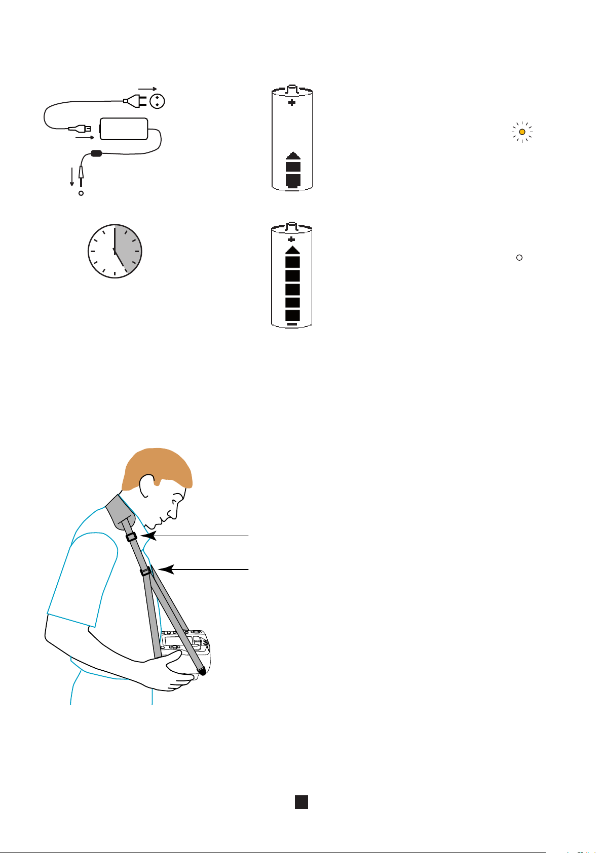
1.2. CHARGING THE BATTERY
Before the first use, start by fully charging the battery. The charging must be done between 10 and 35°C.
Battery charging connector of the device.
The indicator of the
device lights.
Charging time:
approximately 5h
After prolonged storage, the battery may be fully discharged. In this case, the first charge may take longer and the indicator on
the device flashes for the first few minutes.
Set the switch to OFF, but charging is possible when the device is not off,
The indicator goes
off.
1.3. CARRYING THE DEVICE
The 4-point hands-free strap will let you use the device while leaving
your hands free. Snap the four fasteners of the strap onto the four
lugs on the device.
Pass the strap around your neck.
Adjust the length of the strap, then the tilt of the device.
5
Page 6

SET UP
OFF
1.4. CHOICE OF LANGUAGE
OK
OK
SET-UP
Before using the device, first choose the language in which you want the device to display messages.
Set the switch to SET-UP.
Use the directional keypad to select the languages icon:
Press the OK key to validate your
choice.
Select your language, from among those proposed, using the
keys and validate by pressing the OK key again.
6
Page 7

2. PRESENTATION OF THE DEVICE
SET UP
OFF
OK
TEST
Switch for selection
of the measurement
function or SETUP.
USB port for data
transfer to a PC.
Indicator light.
Directional keypad:
four navigation keys
and one validation
key.
TEST button to start
the measurements.
Backlight lighting and adjust-
ment key (contrast and bright-
ness).
Connection ter-
minals.
Help key.
Stud for clipping
on th e 4 -po i nt
hands-free strap.
Four function
keys.
7
Battery charging con-
nector.
Page 8

2.1. FUNCTIONS OF THE DEVICE
The C.A. 6116 installation tester is a portable measuring device with a monochrome graphic display. It is powered by a rechargeable battery with a built-in charger and external power supply unit.
This device is intended to check the safety of electrical installations. It can be used to test a new installation before it is powered
up, to check an existing installation, whether in operation or not, or to diagnose a malfunction in an installation.
Measurement
functions
Controls one thirteen-position switch, one five-key navigator, one keypad with four function keys, one context-
Display 5.7» (115 x 86mm) monochrome graphic LCD display unit, 1/4 VGA (320 x 240 points), with possibility of
voltage
continuity and resistance
insulation resistance
earth resistance (with 3 rods)
loop impedance (Zs)
earth resistance on live circuit (with an auxiliary probe)
selective earth resistance (with a auxiliary probe and an optional current clamp)
line impedance (Zi)
test of residual current devices in ramp mode
test of residual current devices in pulse mode
current (with an optional current clamp)
detection of direction of phase rotation
power (single-phase or balanced three-phase) with display of the voltage and/or current curves
harmonics in voltage and current (with an optional clamp)
sensitive help key, one backlight key, and one TEST button.
backlighting.
2.2. KEYPAD
The actions of the 4 function keys are indicated on the display unit by adjacent icons. They depend on the context.
The help key can be used in all functions. The help function is context-sensitive: it depends on the function.
The directional keypad comprises four navigation keys and one validation key.
In addition to lighting the backlighting, the key is used to adjust:
the contrast of the screen
the brightness of the backlighting
+
sustained
press
+
or
or
sustained
press
8
Page 9

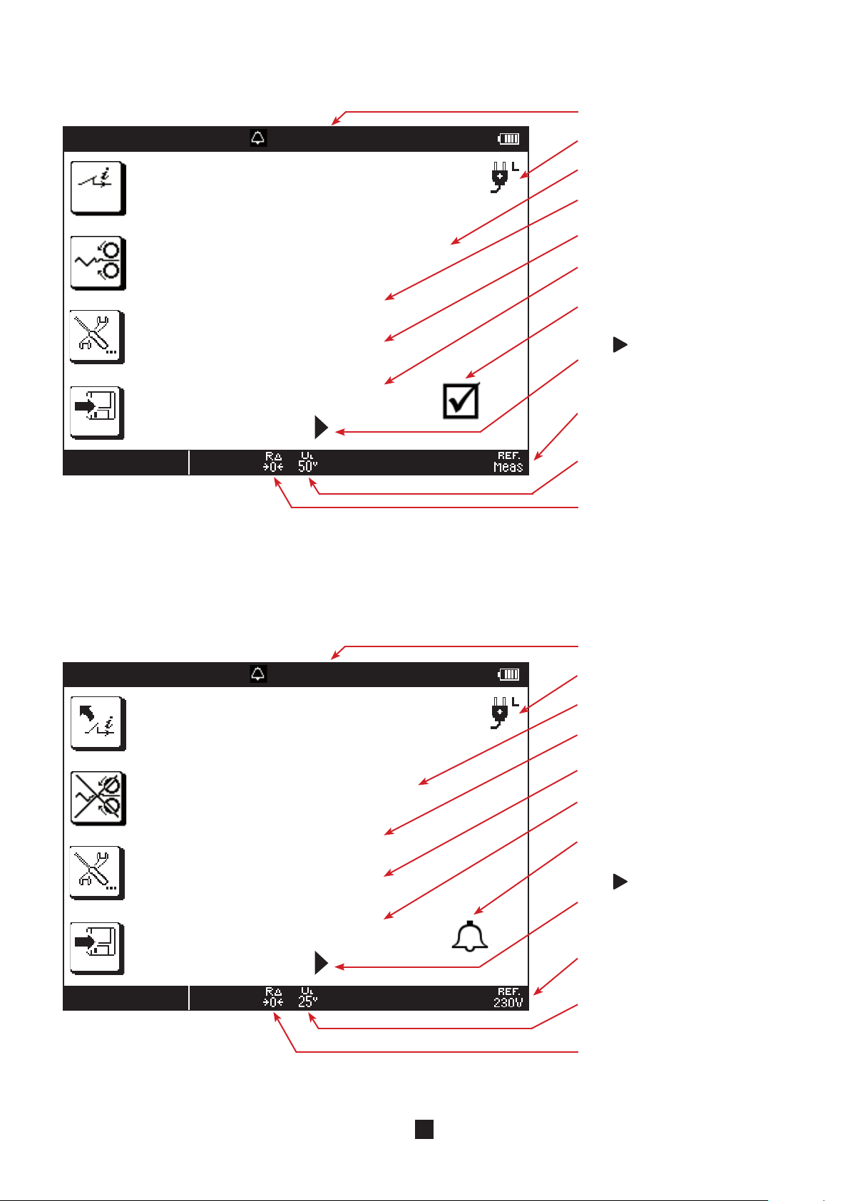
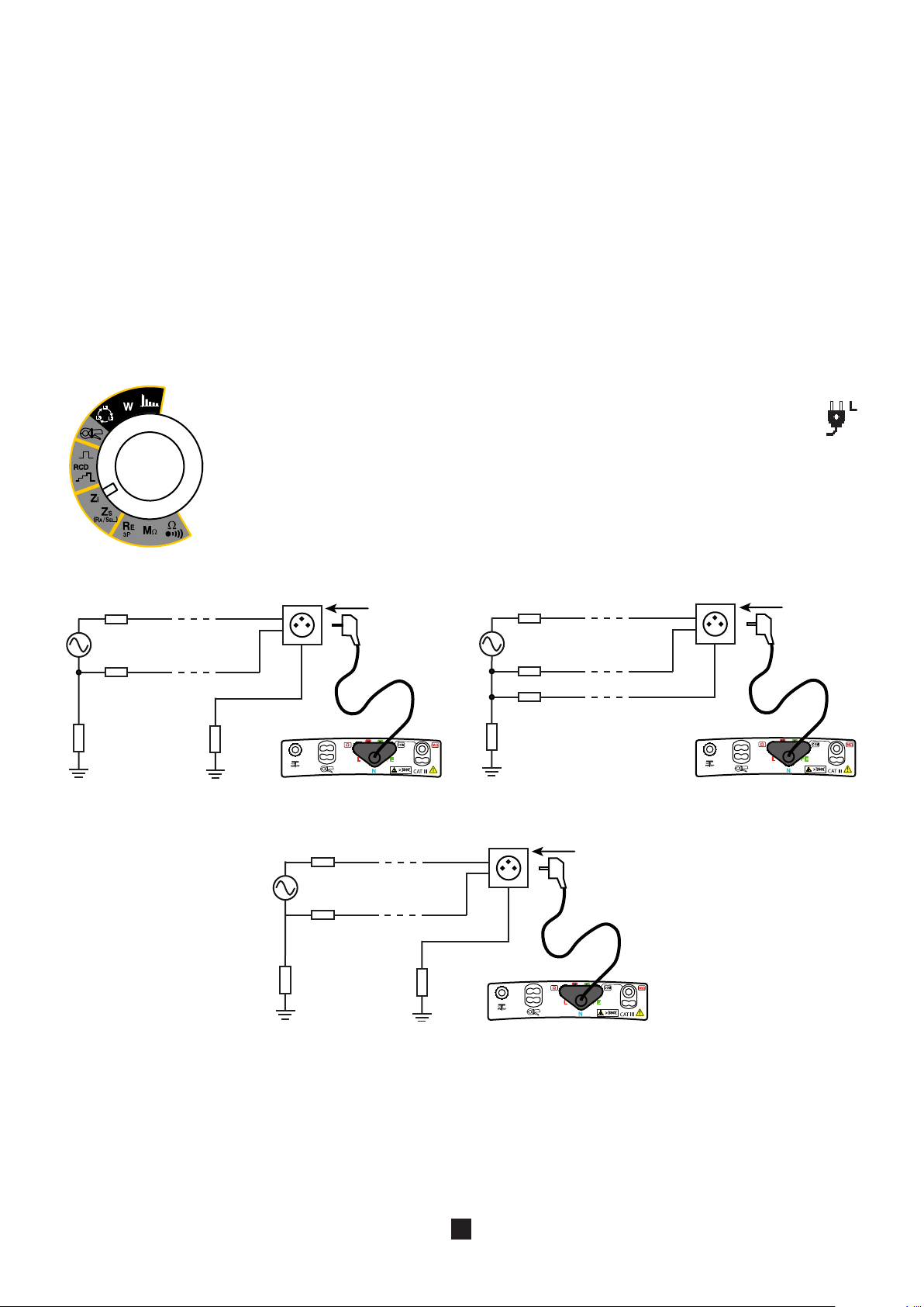
2.3. DISPLAY UNIT
LOOP ZS
02/09/2009 10:47
50 . 0 Ω 50 . 1 Hz
L-PE 230.3 V
L-N 230.4 V
N-PE 0.8 V
12 mA
6 %
➀
➅
➈
➁
➂
➃
➄
➆
➇
Top strip
1
Date and time
2
Alarm threshold
3
Frequency measured
4
Condition of the battery
5
Icons representing the functions of the keys
6
2.4. USB PORT
The USB port of the device is used to transfer the stored data to a PC. This operation requires the prior installation of a specific
peripheral driver and other software.
The USB cord and the associated software are supplied with the device.
➉
11
Position of the phase on the socket outlet
7
Display of measurement results
8
Bottom strip
9
Name of function
10
Information about the measurement in progress
11
9
Page 10
3. PROCEDURE
L
L
The device is configured so that it can be used without changing the parameters. For most measurements, simply select the
measurement function by turning the switch and press the TEST key.
However, you can also parameterize the measurements, using the function keys, or the device itself, using SET-UP.
In addition to an intuitive interface, the C.A. 6116 provides complete help in use and analyses and appraisals. Three types of help
function are available:
On-line help before the measurement can be accessed using the
function and important recommendations.
Error messages appear, as soon as the TEST key is pressed, to report connection errors, measurement parameterizing errors,
out-of-range values, defective installations tested, etc.
On-line help associated with the error messages. Messages containing the
for ways to eliminate the error found.
The user is assumed to be at the reference earth potential. He/she must therefore not be insulated from earth: must not wear
insulating shoes or insulating gloves and must not use a plastic object to press the TEST key.
3.1. VOLTAGE MEASUREMENT
3.1.1. DESCRIPTION OF THE MEASUREMENT PRINCIPLE
Whichever function is chosen, the device always starts by measuring the voltage present on its terminals.
key. It indicates the connections to be made for each
icon invite you to look up the on-line help
It separates the alternating voltage from the direct voltage and compares the amplitudes to decide whether the signal is AC or
DC. In the case of an AC signal, the frequency is measured and the device calculates the RMS value of the AC part and displays
it. In the case of a DC signal, the device does not measure its frequency, but calculates its mean value and displays it.
For measurements made at the network voltage, the device checks that the connection is correct and displays the position of
the phase on the socket outlet. It also checks the presence of a protective conductor on the PE terminal by means of the contact
the user makes with his/her finger by touching the TEST key.
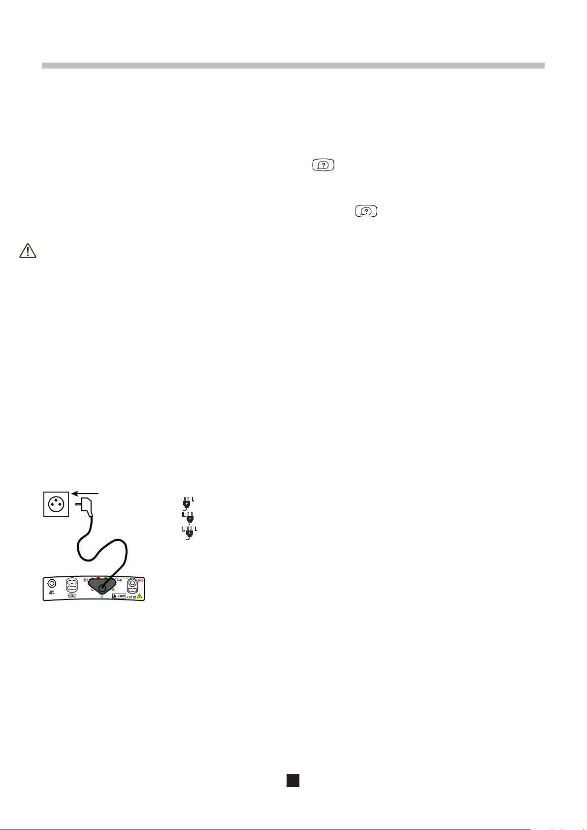
3.1.2. MAKING A MEASUREMENT
Connect the leads to the device to be tested. As soon as the device is powered up, it measures the voltages present on its terminals and displays them, whatever the setting of the switch.
The mains socket outlet of the measuring cable is marked with a white reference spot.
: the phase is on the right-hand contact of the mains plug when the white spot is up.
: the phase is on the left-hand contact of the mains plug when the white spot is up.
: the device cannot determine where the phase is, probably because the PE is not con-
nected or the L and PE conductors are interchanged.
Remark : the terminal identified as L is the one that has the highest voltage with respect to PE;
this does not mean that the other terminal is not at a dangerous voltage.
3.1.3. ERROR REPORTING
The only errors reported in voltage measurement are values outside the voltage and/or frequency measurement range. These
errors are reported in clear language on screen.
10
Page 11

SET UP
OFF
R
3.2. RESISTANCE AND CONTINUITY MEASUREMENT
3.2.1. DESCRIPTION OF THE MEASUREMENT PRINCIPLE
For continuity measurements, the device generates a DC current of 200 or 12 mA, at the user’s discretion, between the W and
COM terminals. It then measures the voltage present between these two terminals and from it deduces the value of R = V/I.
For resistance measurements (current chosen = kW), the device generates a DC voltage between the W and COM terminals. It
then measures the current between these two terminals and from it deduces the value of R = V/I.
In the case of a measurement at high current (200 mA), at the end of one second, the device reverses the direction of the current
and makes another measurement for one second. The result displayed is the mean of these two measurements. It is possible to
make measurements with either the positive or the negative polarity of the current disabled.
For measurements at low current (12 mA or kW), the polarity is positive only.
3.2.2. MAKING A MEASUREMENT
To comply with standard IEC-61557, the measurements must be made at 200 mA. The reversal of the current serves to compensate for any residual electromotive forces and, more important, to check that the continuity is in fact duplex.
When you make continuity measurements that are not contractual, prefer a current of 12 mA. Even though the results cannot be
regarded as those of a normative test, this significantly increases the life of the device between charges and forestalls untimely
tripping of the installations if there is a connection error.
The permanent mode is used to chain measurements without having to press the TEST button each time.
If the object to be measured is permanent, it is better to switch to pulse mode and make a measurement at positive polarity, then
a measurement at negative polarity, manually, in order to leave time for the measurement to settle.
The alarm, if activated, serves to report, by an audible signal, that the measurement is below threshold, making it unnecessary
to look at the display unit to check this point.
Set the switch to W
.
Use the leads to connect the device to be tested between the W and COM terminals of the device. The object to be tested must not be live.
Before starting the measurement, you can configure it by modifying the parameters displayed:
Choice of measurement current: kW, 12 mA or 200 mA (default).
The high current (200 mA) is used to measure only low resistance values, up to 40 W.
The low current (12 mA) is used to make measurements up to 400 W.
The choice kW is used to make resistance measurements up to 400 kW.
To correct for the resistance of the measurement leads (leads and probe tips or alligator clips), for measurements
at 12 and 200 mA (see §3.14).
Pressing the TEST key starts only one measurement (pulse mode).
Pressing the TEST key starts the continuous measurement (permanent mode). To stop
it, you must press the TEST key again. The permanent mode is the default operating
mode.
11
Page 12
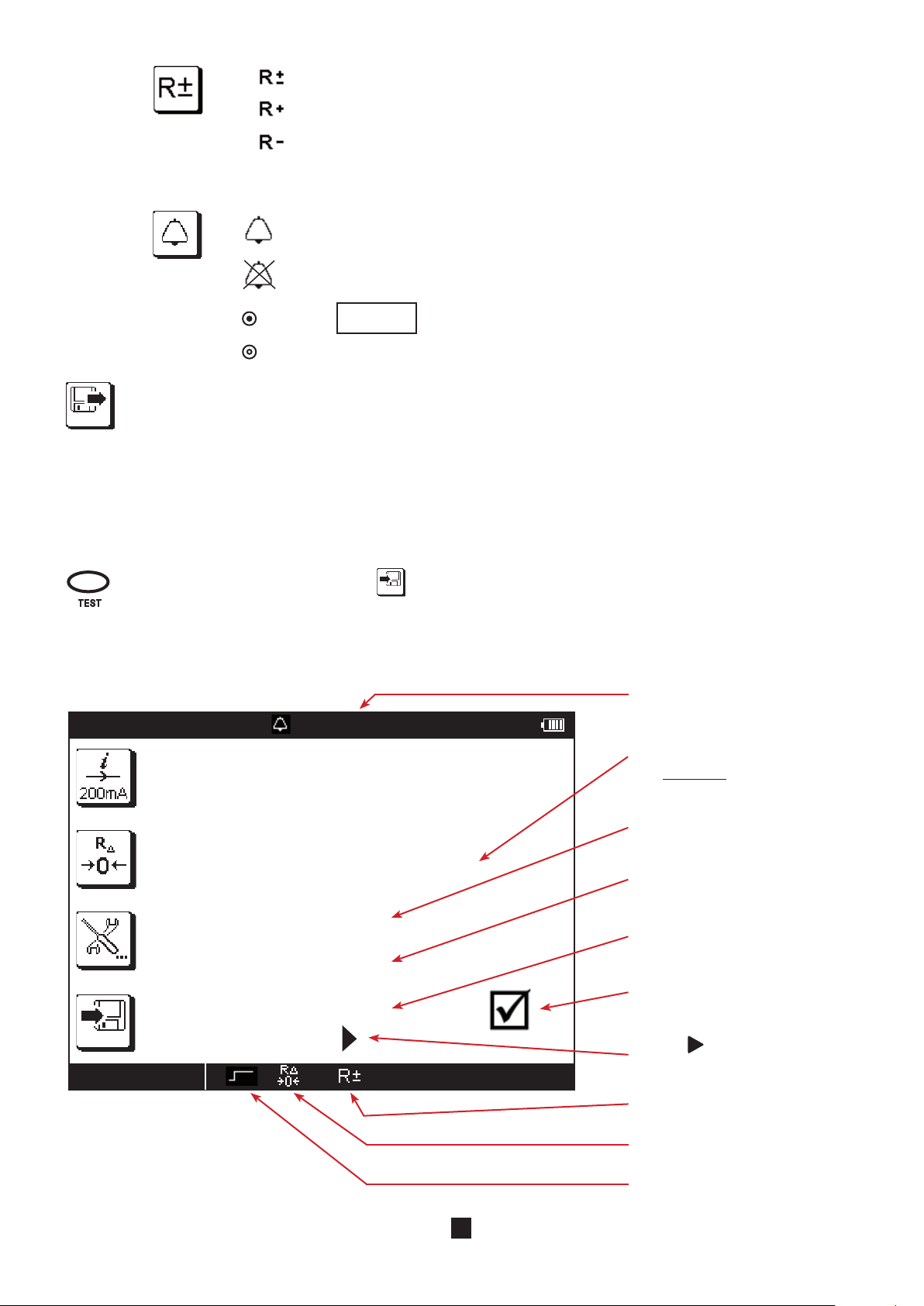
Automatic reversal of polarity for a measurement at 200 mA (default).
6 %
TEST
5 %
CONTINUITY
02/10/2009 10:47
2.00 Ω - - .- Hz
0 . 8 3 Ω
I 2 0 7 . 4 m A
R + 0 . 5 9 Ω
R - 1 . 0 8 Ω
1 %
..\..
1 %
002.00
k Ω
Ω
Measurement at positive polarity only.
Measurement at negative polarity only (for a measurement at 200 mA).
If you want only a single polarity, you must program it again each time you enter the continuity function.
To activate the alarm.
To deactivate the alarm.
To set the alarm threshold; 2W is default (see §3.15).
Before the measurement: to display the measurements already recorded.
During or after the measurement: to record it.
The direction of the arrow indicates whether you can make a reading (arrow pointing out) or a recording (arrow
pointing in).
Once the parameters have been defined, you can start the measurement.
3.2.3. READING OF THE RESULT
In the case of a 200 mA current:
If you selected the pulse mode, press the TEST button once and the measurement stops automatically when it is
over.
If you selected the permanent mode, press the TEST button once to start the measurement and a second time to
stop it, or else press the record key
directly.
Value of the alarm threshold.
Measurement result:
(R+) + (R-)
R =
2
Measurement current.
Measurement with a positive current (R+).
Measurement with a negative current (R-).
Case where the measurement is
below the alarm threshold.
Use the key to see the rest of the
measurement display.
Bipolar measurement.
Compensation for the resistance of
the measurement leads is activated.
Permanent mode.
12
Page 13

1 8 . 4 Ω
I 1 2 . 3 m A
..\..
2.00 Ω - - .- Hz
1 %
CONTINUITY
02/10/2009 10:47
To see the next display page.
CONTINUITE
10/02/2009 10:47
U Ω 0 . 0 V
1 %
../..
2.00 Ω - - .- Hz
External voltage present on the
terminals just before the start of the
measurement.
Use the key to return to the previous display page.
In the case of a 12 mA current, there is no current reversal and only the main measurement is displayed.
Value of the alarm threshold.
Measurement result.
Current measurement.
Case where the measurement is
above the alarm threshold.
Use the
measurement display.
The polarity of the current is positive.
key to see the rest of the
Compensation for the resistance of
the measurement leads is activated.
Pulse mode.
13
Page 14

In the case of a resistance measurement (kW), there is no current reversal and no compensation for the measurement leads.
1 . 5 8 k Ω
1 %
..\..
2.00 kΩ - - .- Hz
CONTINUITY
02/10/2009 10:47
Value of the alarm threshold.
Measurement result.
Case where the measurement is
below the alarm threshold.
Use the
measurement display.
Permanent mode.
3.2.4. ERROR REPORTING
The commonest error in the case of a continuity measurement is the presence of a voltage on the terminals. An error message is
displayed if a voltage greater than 0.5 VRMS is detected and you press the TEST button.
In this case, the continuity measurement is not enabled. Eliminate the cause of the interference voltage and start the measurement over.
Another possible error is measurement of an overly inductive load that prevents the measurement current from stabilizing. In this
case, start the measurement in permanent mode with only one polarity and wait for the measurement to stabilize.
For help with connections or any other information, use the on-line help.
key to see the rest of the
14
Page 15
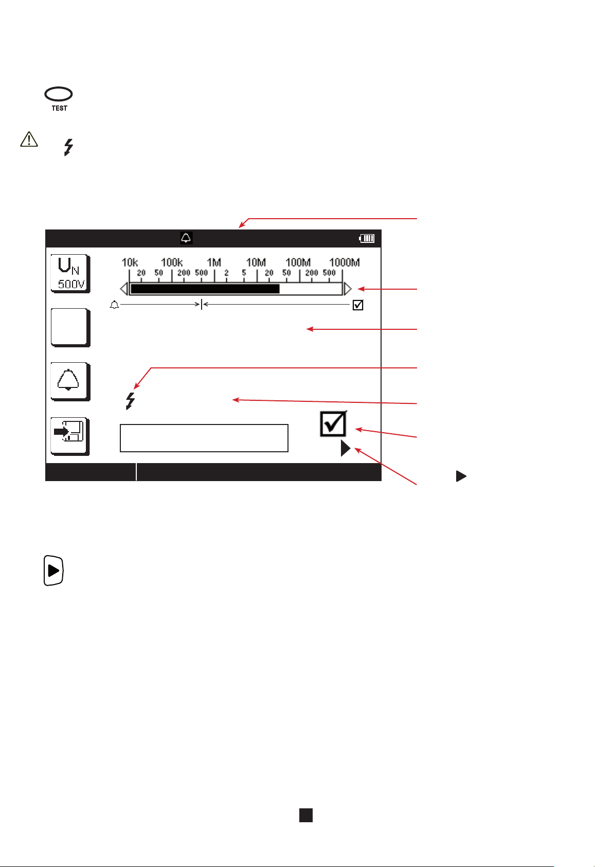
3.3. INSULATION RESISTANCE MEASUREMENT
SET UP
OFF
R
6 %
0500.0
M Ω
k Ω
L3
PE
N
L1
L2
3.3.1. DESCRIPTION OF THE MEASUREMENT PRINCIPLE
The device generates a DC test voltage greater than the nominal voltage chosen UN between the COM and MW terminals. The
value of this voltage depends on the resistance to be measured: it is greater than or equal to UN when R is greater than or equal
to RN = UN /1 mA, and less otherwise. The device measures the voltage and current present between the two terminals and from
them deduces the value of R = V / I.
3.3.2. MAKING A MEASUREMENT
The alarm, if activated, serves to report, by an audible signal, that the measurement is below threshold, making it unnecessary
to look at the display unit to check this point.
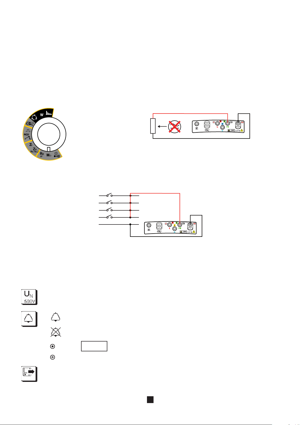
Set the switch to MW.
Generally, an insulation measurement on an installation is made between the interconnected phase(s) and neutral, on the one
hand, and earth, on the other.
Use the leads to connect the device to be tested between the COM and MW
terminals of the device. The object to be tested must not be live.
Remark : To avoid leakage during the insulation measurement, which would
throw off the measurement, it is best not to use the measuring
cable when you make this type of measurement, but two simple
leads.
If the insulation is not sufficient, you must then make the measurement between each of the pairs to locate the fault. It is for this
reason possible to index the recorded value with one of the following values:
L-N/PE, L-N, L-PE, N-PE, L1-PE, L2-PE, L3-PE, L1-N, L2-N, L3-N, L1-L2, L2-L3 or L3-L1
To use the remote control probe, refer to its operating data sheet.
Before starting the measurement, you can configure it by modifying the parameters displayed:
To choose the nominal test voltage UN: 50, 100, 250, 500 (default) or 1000 V.
To activate the alarm.
To deactivate the alarm.
To set the alarm threshold (see §3.15). As default, the threshold is set to
R (kW) = UN / 1 mA.
Before the measurement: to display the measurements already recorded.
During or after the measurement: to record it.
The direction of the arrow indicates whether you can make a reading (arrow pointing out) or a recording (arrow
pointing in).
15
Page 16
TEST
Once the parameters have been defined, you can start the measurement.
INSULATION
02/11/2009 10:47
500 kΩ - - .- Hz
3 1 . 0 6 MΩ
7 s
2 %
Press TEST until the measurement
is stable
..\..
Keep the TEST button pressed until the measurement is stable. The measurement stops when the TEST button
is released.
Before disconnecting the leads or starting another measurement, wait a few seconds for the device tested to be discharged (when
the
symbol disappears from the display unit).
3.3.3. READING OF THE RESULT
Value of the alarm threshold.
The bargraph provides a rapid quantitative indication of the quality of the
insulation.
Measurement result.
The test voltage UN is present and
dangerous.
To see the next display page.
Duration of the measurement.
Case where the measurement is
above the alarm threshold.
Use the key to see the rest of the
measurement display.
16
Page 17

INSULATION
02/11/2009 10:47
500 kΩ - - .- Hz
U M Ω 0 . 0 V
../..
2 %
Press TEST until the measurement
is stable
External voltage present on the
terminals just before the start of the
measurement.
Use the
ous display page.
3.3.4. ERROR REPORTING
The commonest error in the case of an insulation measurement is the presence of a voltage on the terminals. If it is greater than
50 V, the insulation measurement is not enabled. Eliminate the voltage and start the measurement over.
The measurement may be unstable, probably because of an overly capacitive load or an insulation fault. In this case, read the
measurement on the bargraph.
For help with connections or any other information, use the on-line help.
key to return to the previ-
17
Page 18

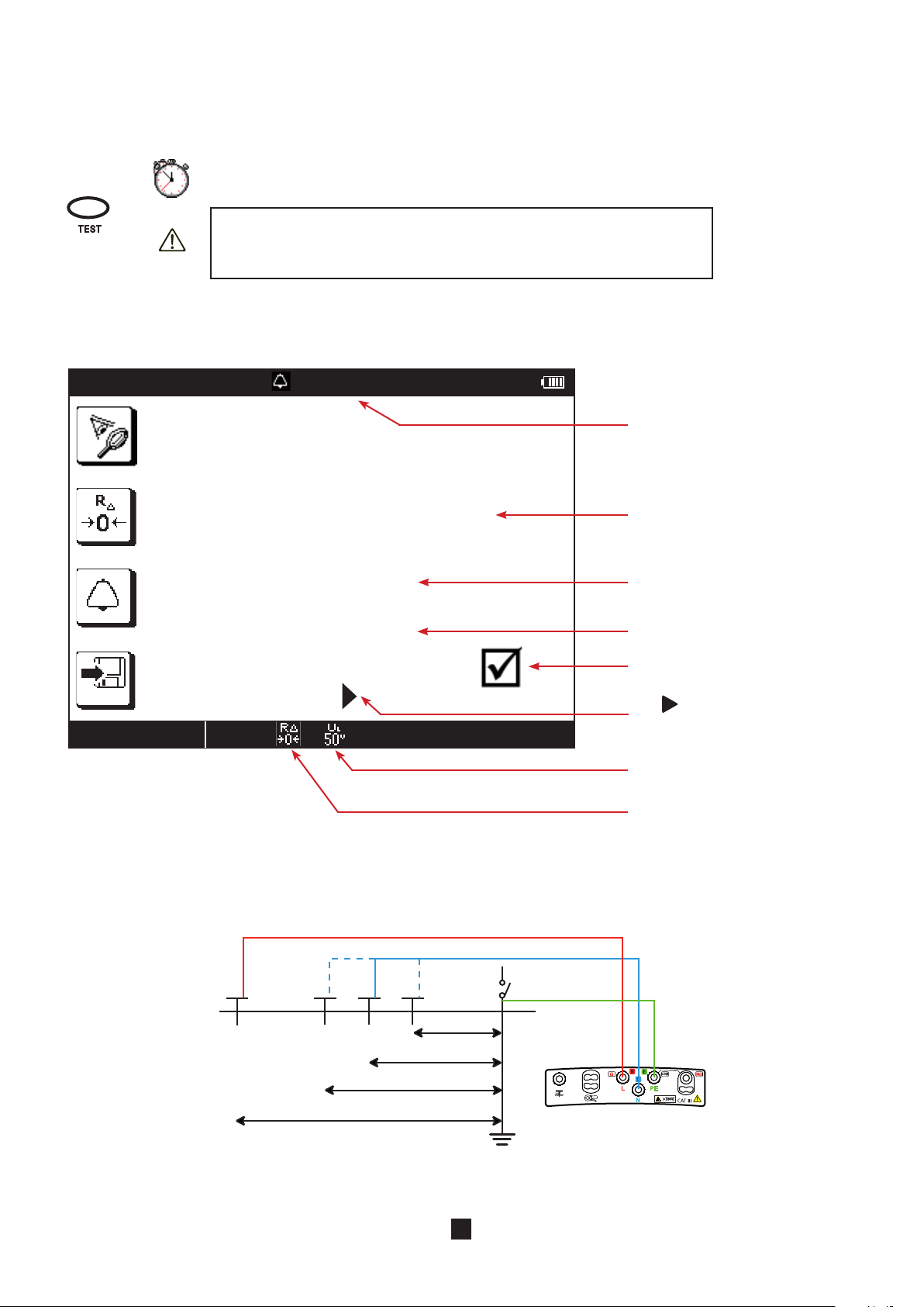
3.4. 3P EARTH RESISTANCE MEASUREMENT
SET UP
OFF
62% d
d
H
S
050.00
k Ω
Ω
6 %
This function is used to measure an earth resistance with two additional rods, the third rod being constituted by the earth electrode to be tested.
It is possible to make a rapid measurement and measure only RE or else to make a more detailed measurement by also measuring the resistances of the rods.
3.4.1. DESCRIPTION OF THE MEASUREMENT PRINCIPLE
The device generates between the H and E terminals a square wave at a frequency of 128 Hz and an amplitude of 35 V. It measures the resulting current, IHE , along with the voltage present between the S and E terminals, USE. It then calculates the value of
RE = USE/IHE.
To measure the resistances of the RS and RH rods, the device internally reverses the E and S terminals and makes a measurement.
It then does likewise with the E and H terminals.
3.4.2. MAKING A MEASUREMENT
There are several measurement methods. We recommend the «62%» method.
Plant the H and S rods in line with the earth electrode. The distance between the S rod
Set the switch to RE 3P.
and the earth electrode must be approximately 62% of the distance between the H rod
and the earth electrode.
In order to avoid electromagnetic interference, we recommend paying out the full length of
the cables, placing them as far apart as possible, and not making loops.
earth
strap
Connect the cables to the H and S terminals. Power down the installation and disconnect the earth strap. Then connect the E
terminal to the earth electrode to be checked.
The alarm, if activated, serves to report, by an audible signal, that the measurement is above threshold, making it unnecessary
to look at the display unit to check this point.
Before starting the measurement, you can configure it by modifying the parameters displayed:
Choice of type of measurement: rapid, to measure RE only (icon crossed out), or detailed, to measure also rod
resistances RS and RH.
To compensate for the resistance of the lead connected to the E terminal, for measurements of low values (see
§3.14).
To activate the alarm.
To deactivate the alarm.
Before the measurement: to display the measurements already recorded.
During or after the measurement: to record it.
The direction of the arrow indicates whether you can make a reading (arrow pointing out) or a recording (arrow
pointing in).
To set the alarm threshold (see §3.15). As default, the threshold is set to 50W.
18
Page 19
EARTH 3P
02/12/2009 10:47
50.0 Ω 50.1 Hz
R E 3 2 . 0 8 Ω
R s 1 . 5 8 k Ω
R h 1 . 3 2 k Ω
3 %
..\..
52% d
d
62% d
72% d
H
S
TEST
If the measurement must be made in a damp environment, remember to change the value of maximum contact voltage UL in
Setup (see §5) and set it to 25 V.
Press the TEST button to start the measurement. The measurement stops automatically.
This symbol invites you to wait while the measurement is in progress.
Do not forget to reconnect the earth strap at the end of the measurement
before powering the installation back up.
3.4.3. READING OF THE RESULT
Value of the alarm threshold.
Measurement result.
3.4.4. VALIDATION OF THE MEASUREMENT
To validate your measurement, move the S rod towards the H rod by 10% of d and make another measurement. Then move the
S rod, again by 10% of d, but towards the earth electrode.
Resistance of the S rod.
Resistance of the H rod.
Case where the measurement is
below the alarm threshold.
key is used to see the voltages
The
before the beginning of the test.
Programmed maximum contact
voltage.
Compensation for the resistance of
the measurement leads is activated.
The 3 measurement results must be the same to within a few percent. If this is the case, the measurement is valid. If not, it is
because the S rod is in the zone of influence of the earth electrode.
19
Page 20

If the resistivity of the ground is homogeneous, it is necessary to increase distance d and repeat the measurements. If the re-
H
S
E
H
S
d2
d1
H
S
E
S
sistivity of the ground is inhomogeneous, the measurement point must be moved either towards the H rod or towards the earth
terminal until the measurement is valid.
3.4.5. POSITIONING OF THE AUXILIARY RODS
To make sure that your earth measurements are not distorted by interference, we recommend repeating the measurement with
the auxiliary rods placed at a different distance and in another direction (for example rotated 90° from the first alignment).
If you find the same values, your measurement is reliable. If the measured values are substantially different, it is probable that
they were influenced by earth currents or a groundwater artery. It may be useful to drive the rods deeper.
If the in-line configuration is not possible, you can plant the rods in a triangle. To validate the measurement, move the S rod on
either side of the line HE.
Avoid routing the connecting cables of the earth rods near or parallel to other cables (transmission or power supply), metal pipes,
rails, or fences, this in order to avoid the risk of cross-talk with the measurement current.
3.4.6. ERROR REPORTING
The commonest errors in the case of an earth measurement are the presence of an interference voltage or rod resistances that
are too high.
If the device detects:
a rod resistance greater than 15kW,
a voltage greater than 25 V on H or on S when the TEST button is pressed.
In these two cases, the earth measurement is not enabled. Move the rods and start the measurement over.
To reduce the resistance of the rods RH (RS), you can add one or more rods, two metres apart, in the H (S) branch of the circuit.
You can also drive them deeper and pack the earth around them, or wet it with a little water.
For help with connections or any other information, use the on-line help.
20
Page 21
3.5. LOOP IMPEDANCE MEASUREMENT (ZS)
L
PE
N
Rb
RE
RN
RL
L
PE
N
Rb
RN
RL
Ra
SET UP
OFF
In a TT type installation, the loop impedance measurement is an easy way to make an earth measurement without planting any
rods. The result obtained, ZS, is the loop impedance of the installation between the L and PE conductors. It is only very slightly
greater than the earth resistance, to which it adds the earthing resistance of the transformer and the resistance of the cables,
which are both negligible.
In a TN or TT type installation, the loop impedance measurement also makes it possible to calculate the short-circuit current and
size the protections of the installation (fuse or circuit-breaker).
This measurement cannot be made in an IT type installation because of the high earthing impedance of the supply transformer,
which may even be completely isolated from earth.
3.5.1. DESCRIPTION OF THE MEASUREMENT PRINCIPLE
The device starts by generating pulses having a duration of 300 µs and an amplitude of at most 5 A between the L and N terminals.
This first measurement is used to determine ZL.
It then applies a low current, 6, 9 or 12 mA at the user’s discretion, between the L and PE terminals. This low current serves to
avoid tripping residual current devices of which the nominal current is greater than or equal to 30 mA. This second measurement
is used to determine ZPE.
The device then calculates loop resistance Z
= Z
S
= ZL+ZPE , and short-circuit current Ik = U
L-PE
LPE/ZS
.
The value of Ik serves to check the proper sizing of the circuit-breaker.
For greater accuracy, it is possible to measure ZS with a high current (TRIP mode), but this measurement may trip out the installation.
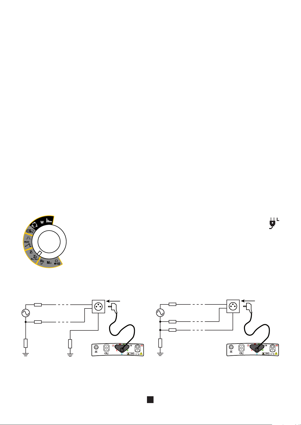
3.5.2. MAKING A MEASUREMENT
Connect the measuring cable to the device, then to the socket outlet of the instal-
Set the switch to ZS (RA/SEL.).
lation to be tested.
At the time of connection, the device first checks that the voltages present
on its terminals are correct, then determines the position of the phase (L) and
of the neutral (N) with respect to the protective conductor (PE) and displays
it. If necessary, it then automatically switches the L and N terminals so that
the loop measurement can be made without modifying the connections of
the terminals of the device.
If possible, first disconnect all loads from the network on which you make the loop
measurement.
It is possible to eliminate this step if you use a measurement current of 6 mA, which
allows a leakage current of up to 9 mA for an installation protected by a 30 mA
residual current device.
Case of a TT installation
Note: in trip mode, it is not necessary to connect the N terminal.
For a more accurate measurement, you can choose a high current (TRIP mode), but the circuit-breaker that protects the installation may trip out. To prevent this, you can short-circuit the circuit-breaker during the measurement, as follows:
21
Case of a TN installation
Page 22
12 mA
050.00
k Ω
Ω
(Ik)
6 %
TEST
010.00
A
k A
L
N
RCD
For the safety of the installation and of the users, you must not forget to put
the residual current device back in service after the measurement.
The alarm, if activated, serves to report, by an audible signal, that the measurement is above threshold, making it unnecessary
to look at the display unit to check this point.
Smoothing the signal, rather than making several measurements and calculating a mean, yields a stable measurement directly.
But the measurement then takes longer.
Before starting the measurement, you can configure it by modifying the parameters displayed:
Choice of measurement current in non-tripping mode: 6, 9, 12 mA (default)
or TRIP mode to use a high current that will give a more stable measurement.
To activate or deactivate the smoothing of the signal.
To compensate for the resistance of the measurement leads, for measurements of low values (see
§3.14).
The device proposes choosing the voltage for the Ik calculation from among the following values:
MEAS (the measured voltage value),
the voltage of the old standard (for example 220),
the voltage of the current standard (for example 230).
Depending on the voltage U
if 170<ULN<270 V: MEAS (default), 220 V, or 230 V.
if 90<ULN<150 V: MEAS (default), 110 V or 127 V.
if 300<ULN<550 V: MEAS (default), 380 V or 400 V.
To deactivate the alarm.
Z-R
Ik
Before the measurement: to display the measurements already recorded.
During or after the measurement: to record it.
The direction of the arrow indicates whether you can make a reading (arrow pointing out) or a recording (arrow
pointing in).
To activate the alarm on Z
To activate the alarm on Ik.
measured, the device proposes the following choices:
LN
(in TRIP mode) or on R
LPE
To set the alarm threshold (see §3.15). As default,
the threshold is set to 50 W.
To set the alarm threshold (see §3.15). As default,
the threshold is set to 10 kA.
(in non-tripping mode).
LPE
Press the TEST button to start the measurement. The measurement stops automatically.
When the TEST key is pressed, the device checks that the contact voltage is less than UL. If not, it does not make
the loop impedance measurement.
This symbol invites you to wait while the measurement is in progress.
22
Page 23
LOOP Zs
02/16/2009 10:47
50 .0 Ω 50 . 1 Hz
12 mA
4 %
..\..
I k 2 0 6.6 A
Z s 1 . 2 4 Ω
R s 1 . 0 4 Ω
L s 0 . 2 m H
3.5.3. READING OF THE RESULT
LOOP Zs
02/17/2009 10:47
10.0 Ω 50 . 1 Hz
..\..
I k 3.1 A
Z s 3 4 . 6 1 Ω
R s 3 4 . 4 8 Ω
L s 9 . 4 m H
4 %
In the case of a non-tripping measurement, with smoothing:
Value of the alarm threshold.
Position of the phase on the socket outlet.
Value of the short-circuit current.
Value of the impedance.
Value of the resistance.
Value of the inductance.
Case in which the measurement is
below the alarm threshold.
The key is used to access the
next page to see the voltages before
the beginning of the test.
Value of the reference voltage for the
calculation of Ik.
Programmed maximum contact
voltage.
In the case of a measurement with tripping (TRIP) and without smoothing:
Compensation for the resistance of
the measurement leads is activated.
Value of the alarm threshold.
Position of the phase on the socket outlet.
Value of the short-circuit current.
Value of the impedance.
Value of the resistance.
Value of the inductance.
Case where the measurement is
above the alarm threshold.
The key is used to access the
next page to see the voltages before
the beginning of the test.
Value of the reference voltage for the
calculation of Ik.
Programmed maximum contact
voltage.
Compensation for the resistance of
the measurement leads is activated.
23
Page 24
3.6. MEASUREMENT OF THE LINE IMPEDANCE (Zi)
SET UP
OFF
L
PE
N
Rb
RE
RN
RL
L
PE
N
Rb
RN
RL
Ra
L
PE
N
RN
RL
Ra
Z
The loop impedance measurement Zi (L-N, L1-L2, or L2-L3 or L1-L3) is used to calculate the short-circuit current and size the protections of the installation (fuse or circuit-breaker), whatever type of neutral the installation uses.
3.6.1. DESCRIPTION OF THE MEASUREMENT PRINCIPLE
The device generates pulses having a duration of 300 µs and an amplitude of at most 5 A between the L and N terminals. It then
measures the voltages UL and UN and from them deduces Zi.
The device then calculates the short-circuit current Ik = U
tions of the installation.
3.6.2. MAKING A MEASUREMENT
Set the switch to Zi.
Connect the measuring cable to the device, then to the socket outlet of the installation to be tested.
At the time of connection, the device first checks that the voltages present
on its terminals are correct, then determines the position of the phase (L) and
of the neutral (N) with respect to the protective conductor (PE) and displays
it. If necessary, it then automatically switches the L and N terminals so that
the line impedance measurement can be made without modifying the connections of the terminals of the device.
If you use the measuring cable that is terminated by three leads, connect the PE lead
(green) to the N lead (blue). Otherwise, the device cannot display the position of the
phase. But this does not prevent making the measurement.
Case of a TT installation Case of a TN installation
the value of which serves to check the proper sizing of the protec-
LN/Zi
Case of an IT installation
The alarm, if activated, serves to report, by an audible signal, that the measurement is above threshold, making it unnecessary
to look at the display unit to check this point.
Smoothing the signal, rather than making several measurements and calculating a mean, yields a stable measurement directly.
But the measurement then takes longer.
24
Page 25

6 %
TEST
050.00
k Ω
Ω
(Ik)
Before starting the measurement, you can configure it by modifying the parameters displayed:
010.00
A
k A
To activate or deactivate the smoothing of the signal.
To compensate for the resistance of the measurement leads, for measurements of low values (see §3.14).
The device proposes choosing the voltage for the Ik calculation from among the following values:
MEAS (the measured voltage value),
the voltage of the old standard (for example 220 V),
the voltage of the current standard (for example 230 V).
Depending on the voltage ULN measured, the device proposes the following choices:
if 170<U
if 90<ULN<150 V: MEAS (default), 110 V or 127 V.
if 300<ULN<550 V: MEAS (default), 380 V or 400 V.
<270 V: MEAS (default), 220 V, or 230 V.
LN
To deactivate the alarm.
Z-R
Ik
Before the measurement: to display the measurements already recorded.
During or after the measurement: to record it.
The direction of the arrow indicates whether you can make a reading (arrow pointing out) or a recording (arrow
pointing in).
Press the TEST button to start the measurement. The measurement stops automatically.
When the TEST key is pressed, the device checks that the contact voltage is less than UL. If not, it does not make
the loop impedance measurement.
This symbol invites you to wait while the measurement is in progress.
To activate the alarm on Zi.
To set the alarm threshold (see §3.15). As default,
the threshold is set to 50 W.
To activate the alarm on Ik.
To set the alarm threshold (see §3.15). As default,
the threshold is set to 10 kA.
25
Page 26

3.6.3. READING OF THE RESULT
LOOP Zi
02/18/2009 10:47
50 . 0 Ω 50 . 1 Hz
..\..
I k 1 3 1 6 A
Z i 0 . 2 9 Ω
R i 0 . 1 5 Ω
L i 0 . 8 m H
5 %
Value of the alarm threshold.
Position of the phase on the socket outlet.
Value of the short-circuit current.
Value of the impedance.
Value of the resistance.
Value of the inductance.
Case where the measurement is
below the alarm threshold.
key is used to access the
The
next page to see the voltages before
the beginning of the test.
Value of the reference voltage for the
calculation of Ik.
Programmed maximum contact
voltage.
Compensation for the resistance of
the measurement leads is activated.
26
Page 27

3.7. EARTH MEASUREMENT ON LIVE CIRCUIT (ZA, RA)
SET UP
OFF
L
PE
N
Rb
RN
RL
Ra
> 25 m
L
PE
N
RN
RL
Ra
> 25 m
Z
This function is used to make an earth resistance measurement in a place where it is impossible to make a 3P earth measurement
or to disconnect the earth connection strap, often the case in an urban environment.
This measurement is made without disconnecting the earth, with only one additional rod, saving time with respect to a conventional earth measurement with two auxiliary rods.
In the case of a TT type installation, this measurement is a very simple way to measure the earth of frame grounds.
In the case of an IT type installation, too, this measurement is a very simple way to measure the earth of frame grounds provided
that:
the supply transformer is not isolated from earth but connected to it via an impedance,
and the installation in not in a first fault state. Check the indication given by the PIT.
In the case of a TN type installation, to determine the value of each of the earths put in parallel, it is necessary to perform a selective earth measurement on live circuit using a current clamp (see §3.8). Without this clamp, what you find is the value of the
global earth connected to the network, which is rather meaningless.
It is then more useful to measure the loop impedance to size the fuses and circuit-breakers, and to measure the fault voltage to
check the protection of persons.
3.7.1. DESCRIPTION OF THE MEASUREMENT PRINCIPLE
The device starts by making a loop measurement ZS (see §3.5) with a low current or a high current, at the user’s discretion. It
then measures the potential between the PE conductor and the auxiliary rod and from it deduces R
chosen by the user.
= U
A
/I, I being the current
PI-PE
For greater accuracy, it is possible to make the measurement with a high current (TRIP mode), but this measurement may trip
out the installation.
3.7.2. MAKING A MEASUREMENT
Connect the measuring cable to the device, then to the socket outlet of the instal-
Set the switch to Z
S (RA/SEL.).
lation to be tested.
At the time of connection, the device detects the positions of the phase (L)
and of neutral (N) with respect to the protective conductor (PE) and displays
them. If necessary, it then automatically switches the L and N terminals so
that the loop measurement can be made without modifying the connections
of the terminals of the device.
If possible, first disconnect all loads from the network on which you make the earth
measurement on line circuit.
It is possible to eliminate this step if you use a measurement current of 6 mA, which
allows a leakage current of up to 9 mA for an installation protected by a 30 mA residual current device.
Plant the auxiliary rod at a distance of more than 25 metres from the earth electrode and
connect it to the
Case of a TT installation
(RA SEL) terminal of the device. The symbol is then displayed.
Case of an IT installation
27
Page 28

L
PE
N
Rb
RE
RN
RL
PE
Ra
> 25 m
Case of a TN installation
(Ik)
12 mA
L
N
To make this measurement, you can choose:
either a low current which avoids any untimely tripping out of the installation but gives only the earth resistance (RA).
or a high current (TRIP mode), which yields a more accurate earth impedance (ZA) with good measurement stability. To avoid
tripping out the installation, you can short-circuit the circuit-breaker during the measurement, as follows:
RCD
For the safety of the installation and of the users, you must not forget to put
the residual current device back in service after the measurement.
The alarm, if activated, serves to report, by an audible signal, that the measurement is above threshold, making it unnecessary
to look at the display unit to check this point.
Smoothing the signal, rather than making several measurements and calculating a mean, yields a stable measurement directly.
But the measurement then takes longer.
Before starting the measurement, you can configure it by modifying the parameters displayed:
Choice of measurement current: 6, 9, 12 mA (default),
or TRIP to use a high current that will yield a more stable measurement.
To activate or deactivate the smoothing of the signal.
To compensate for the resistance of the measurement leads, for measurements of low values (see
§3.14).
The device proposes choosing the voltage for the Ik calculation from among the following values:
MEAS (the measured voltage value),
the voltage of the old standard (for example 220 V),
the voltage of the current standard (for example 230 V).
Depending on the voltage ULN measured, the device proposes the following choices:
if 170<ULN<270 V: MEAS (default), 220 V or 230 V.
if 90<ULN<150 V: MEAS (default), 110 V or 127 V.
if 300<ULN<550 V: MEAS (default), 380 V or 400 V.
28
Page 29

TEST
6 %
050.00
k Ω
Ω
To deactivate the alarm.
010.00
A
k A
EARTH 1P (Ra)
02/20/2009 10:47
50 . 0 Ω 50 . 1 Hz
I K 4 6 8 A
U
FK 0.6 V
6 %
..\..
UFk
Z-R
Ik
Before the measurement: to display the measurements already recorded.
During or after the measurement: to record it.
The direction of the arrow indicates whether you can make a reading (arrow pointing out) or a recording (arrow
pointing in).
Press the TEST button to start the measurement. The measurement stops automatically.
This symbol invites you to wait while the measurement is in progress.
To activate the alarm on ZA (in TRIP mode) or on RA (in non-tripping mode).
To set the alarm threshold (see §3.15). As default,
the threshold is set to 50 W.
To activate the alarm on Ik (in TRIP mode only).
To set the alarm threshold (see §3.15). As default,
the threshold is set to 10 kA.
3.7.3. READING OF THE RESULT
In the case of a measurement with a high current (TRIP mode), without smoothing:
Value of the alarm threshold.
Position of the phase on the socket outlet.
Value of the short-circuit current.
Earth electrode fault voltage in the
event of a short-circuit.
Case where the measurement is
above the alarm threshold.
Use the
display of the measurement.
Value of the reference voltage for the
calculation of Ik.
The rod is connected.
key to see the rest of the
UFk is calculated only in earth measurement on live circuit with a high current (TRIP mode). UFk = Ik x ZA.
Programmed maximum contact
voltage.
Compensation for the resistance of
the measurement leads is activated.
29
Page 30

..\..
02/20/2009 10:47
50 . 0 Ω 50 . 1 Hz
Z A 2 5.1 0 Ω
R a 2 4 . 8 Ω
L
a 5 . 6 m H
6 %
UFk
..\..
EARTH 1P (Ra)
To see the next display page.
Value of the impedance.
Value of the resistance.
Value of the inductance.
The third page is used to see the voltages U
, U
, U
LN
LPE
NPE
Use the
display of the measurement and the
key to return to the previous
page.
and on the rod ( ) before the measurement.
key to see the rest of the
30
Page 31

02/19/2009 10:47
50 . 0 Ω 50 . 1 Hz
R A 2 5.1 0 Ω
12 mA
6 %
..\..
EARTH 1P (Ra)
In the case of a measurement with a low current and smoothing, the first display screen is the following:
Value of the alarm threshold.
Position of the phase on the socket outlet.
Measurement result.
Case where the measurement is
below the alarm threshold.
key is used to access the
The
next page to see the voltages before
the beginning of the test.
Value of the reference voltage for the
calculation of Ik.
The rod is connected.
3.7.4. VALIDATION OF THE MEASUREMENT
Move the rod ± 10% of the distance from the earth electrode and make two more measurements. The 3 measurement results
must be the same to within a few percent. In this case the measurement is valid.
If this is not the case, it is because the rod is in the zone of influence of the earth electrode. You must then move the rod away
from the earth electrode and redo the measurements.
Programmed maximum contact
voltage.
Compensation for the resistance of
the measurement leads is activated.
31
Page 32

3.8. SELECTIVE EARTH MEASUREMENT ON LIVE CIRCUIT
SET UP
OFF
L
PE
N
Rb
RE
RN
RL
PE
Ra3
> 25 m
Ra2
Ra1
L
PE
N
Rb
RN
RL
> 25 m
Ra3
Ra2
Ra1
L
N
This function is used to make an earth measurement and to select one earth from among others, in parallel, and measure it. It
requires the use of an optional current clamp.
3.8.1. DESCRIPTION OF THE MEASUREMENT PRINCIPLE
The device starts by making a loop measurement ZS between L and PE (see §3.5) with a high current, and therefore with a risk of
tripping out the installation. This high current must be used to ensure that the current flowing in the clamp is large enough to be
measured. The device then measures the current flowing in the circuit surrounded by the clamp. Finally, it measures the potential
of the PE conductor with respect to the auxiliary rod and from it deduces R
the clamp.
3.8.2. MAKING A MEASUREMENT
ASEL
= U
PI-PE
/ I
, I
being the current measured by
SEL
SEL
Set the switch to ZS (RA/SEL.).
Connect the measuring cable to the device, then to the socket outlet of the installation to be tested.
At the time of connection, the device detects the positions of the phase (L)
and of neutral (N) with respect to the protective conductor (PE) and displays
them. If necessary, it then automatically switches the L and N terminals so
that the measurement can be made without modifying the connections of
the terminals of the device.
Plant the auxiliary rod at a distance of more than 25 metres from the earth electrode
and connect it to the (RA SEL) terminal of the device. The symbol is then displayed.
Connect the clamp to the device; the symbol is displayed. Then place it on the
earth circuit to be measured.
Case of a TN installation
Case of a TT installation
For greater accuracy, the measurement is made with a high current (TRIP mode). To avoid tripping out the circuit-breaker that
protects the installation, you can short-circuit the circuit-breaker during the measurement, as follows:
RCD
For the safety of the installation and of the users, you must not forget to put
the residual current device back in service after the measurement.
32
Page 33

6 %
(Ik)
UFk
050.00
k Ω
Ω
The alarm, if activated, serves to report, by an audible signal, that the measurement is above threshold, making it unnecessary
010.00
A
k A
TEST
to look at the display unit to check this point.
Smoothing the signal, rather than making several measurements and calculating a mean, yields a right measurement directly.
But the measurement then takes longer.
Before starting the measurement, you can configure it by modifying the parameters displayed:
The measurement current must be a high current (TRIP mode).
UFk is calculated only in an earth measurement on live circuit with a high current (TRIP mode). UFk = Ik x ZA.
To activate or deactivate the smoothing of the signal.
To compensate for the resistance of the measurement leads, for measurements of low values (see
§3.14). But the compensation is not useful for this measurement.
The device proposes choosing the voltage for the Ik calculation from among the following values:
MEAS (the measured voltage value),
the voltage of the old standard (for example 220 V),
the voltage of the current standard (for example 230 V).
Depending on the voltage ULN measured, the device proposes the following choices:
if 170<U
if 90<ULN<150 V: MEAS (default), 110 V or 127 V.
if 300<ULN<550 V: MEAS (default), 380 V or 400 V.
<270 V: MEAS (default), 220 V or 230 V.
LN
To deactivate the alarm.
Z-R
Ik
Before the measurement: to display the measurements already recorded.
During or after the measurement: to record it.
The direction of the arrow indicates whether you can make a reading (arrow pointing out) or a recording (arrow
pointing in).
Press the TEST button to start the measurement. The measurement stops automatically.
This symbol invites you to wait while the measurement is in progress.
To activate the alarm on R
To activate the alarm on Ik (in TRIP mode only).
ASEL
.
To set the alarm threshold (see §3.15). As default,
the threshold is set to 50 W.
To set the alarm threshold (see §3.15). As default,
the threshold is set to 10 kA.
33
Page 34

3.8.3. READING OF THE RESULT
EARTH Ra Sel.
02/23/2009 10:47
100 Ω 50 . 1 Hz
7 %
..\..
UFk
R a sel 1 5.4 2 Ω
Z a 2 5 . 1 2 Ω
R a 2 4 . 8 2 Ω
L a 5 . 6 m H
I k a 7 5 . 1 A
Value of the alarm threshold.
Measurement result.
Value of the impedance.
Value of the resistance.
Value of the inductance.
Value of the short-circuit current.
Case where the measurement is
above the alarm threshold.
The key is used to access the
next page to see the voltages before
the beginning of the test.
Value of the reference voltage for the
calculation of Ik.
The second page is used to see the value of the voltages ULN, U
3.8.4. ERROR REPORTING ((LOOP, EARTH ON LIVE CIRCUIT, AND SELECTIVE EARTH ON LIVE CIRCUIT)
The commonest errors in the case of a loop impedance measurement or earth measurement on live circuit are:
A connection error.
An earth rod resistance that is too high (>15 kW): reduce it by packing the earth around the rod and moistening it.
A voltage on the protective conductor that is too high.
A voltage on the rod that is high: move the rod out of the influence of the earth electrode.
Tripping in the non-tripping mode: reduce the test current.
A current measured by the clamp in selective earth on live circuit that is too low: the measurement is not possible.
ATTENTION : the user may be charged with static electricity, for example by walking on a carpet. In this case, when he/she
The rod is connected.
Programmed maximum contact
voltage.
Compensation for the resistance of
the measurement leads is activated.
The clamp is connected.
, U
LPE
presses the TEST button, the device displays the error message «earth potential too high». The user must then be
discharged by touching an earth before making the measurement.
and on the rod ( ) before the measurement.
NPE
For help with connections or any other information, use the on-line help.
34
Page 35

3.9. TEST OF RESIDUAL CURRENT DEVICE
SET UP
OFF
Rb
RN
RL
L
N
PE
Ra
The device can be used to perform three types of test on residual current devices (or switches):
a tripping test in ramp mode,
a tripping test in pulse mode,
a non-tripping test.
The test in ramp mode serves to determine the exact RCD tripping current.
The test in pulse mode serves to determine the differential trip time.
The non-tripping test serves to check that the RCD does not trip out at a current of 0.5 IDN. For the test to be valid, the leakage
current must be negligible with respect to 0.5 IDN and, to ensure this, all loads connected to the installation protected by the RCD
that is being tested must be disconnected.
3.9.1. DESCRIPTION OF THE MEASUREMENT PRINCIPLE
For each of the three types of test, the device starts by checking that the RCD can be tested without compromising the user’s
safety, i.e. without causing the fault voltage, UF , to exceed 50 V (or 25 V or 65 V according to what is defined in the set-up for UL ).
It therefore starts by generating a low current (<0.4 IDN) in order to measure ZS, as it would for a loop impedance measurement.
It then calculates UF = ZS x IDN (or UF = ZS x 2 IDN depending on the type of test requested), which will be the voltage produced
during the test. If this voltage is greater than UL, the device does not perform the test. The user can then reduce the measurement current (to 0.2 or 0.3 IDN) so that the test current + the leakage current present in the installation will not lead to a voltage
greater than UL.
For a more accurate measurement of the fault voltage, we recommend planting an auxiliary rod, as for earth measurements on live
circuits. The device then measures RA and calculates UF = RA x IDN (or UF = RA x 2 IDN depending on the type of test requested).
Once this first part of the measurement has been made, the device goes on to the second part, which depends on the type of
test.
For the ramp mode test, the device generates a sinusoidal current of which the amplitude increases gradually from 0.3 to
1.06 IDN between the L and PE terminals. When the RCD opens the circuit, the device displays the exact value of the tripping
current and the trip time. This time is an indication and may differ from the trip time in pulse mode, which is closer to the
operational reality.
For the pulse mode test, the device generates a sinusoidal current at the mains frequency, having an amplitude of IDN, 2 IDNor
5 IDN between the L and PE terminals, lasting at most 500 ms. And it measures the time the circuit-breaker takes to open the
circuit. This time must be less than 500 ms.
For the non-tripping test, the device generates a current of 0.5 IDN for one or two seconds, depending on what the user has
programmed. Normally, the circuit-breaker must not open the circuit.
In all cases, if the circuit-breaker does not trip out, the device then sends a current pulse between the L and N terminals. If the
circuit opens, it means that the circuit-breaker was incorrectly installed (N and PE reversed).
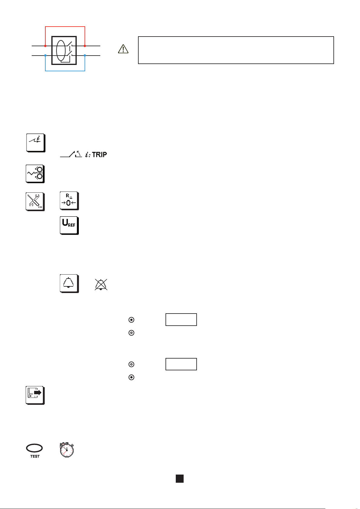
3.9.2. PERFORMING A TEST IN RAMP MODE
Connect the measuring cable to the device, then to a socket outlet included in the circuit
Set the switch to RCD .
protected by the circuit-breaker to be tested.
At the time of connection, the device detects the positions of the phase (L) and
of neutral (N) with respect to the protective conductor (PE) and displays them. If
necessary, it then automatically switches the L and N terminals so that the test
can be done without modifying the connections of the terminals.
RCD
35
Page 36

If possible, first disconnect all loads from the network on which you test the RCD. This prevents interference with the test by any
30 mA
S
0.3 I∆N
Rb
RN
RL
L
N
blue
green
red
RCDRCD
30 mA
300 mA
Ra
PE
Rb
RN
RL
L
N
Ra
> 25 m
PE
leakage currents due to these loads.
If you have a current clamp, you can measure the leakage current (see §3.10) at the RCD and so make allowance for it during
the test.
RCD
To make a more accurate measurement of the fault
voltage, plant the auxiliary rod at a distance of more
than 25 metres from the earth electrode and connect it
to the
(RA SEL) terminal of the device. The symbol
is then displayed.
Particular case:
To test a residual current device located downstream of another residual current device having a
smaller nominal current, you must use the measuring cable terminated by 3 leads and make the connections shown opposite (upstream-downstream
method).
Before starting the measurement, you can configure it by modifying the parameters displayed:
Choice of the nominal current of the residual current device IDN: VAR. (variable: the user programs a value between
6 and 999 mA), 10 mA, 30 mA (default), 100 mA, 300 mA, 500 mA, 650 mA, or 1000 mA.
Choice of type of residual current device: STD (standard),
or G (the S type is tested with a current of 2 IDN
as default).
Choice of the form of the test signal:
signal that starts with a positive alternation,
signal that starts with a negative alternation,
signal containing only positive alternations,
signal containing only negative alternations.
To restore the factory adjustment parameters: IDN = 30 mA, STD and
To choose a test current for the check of U
For users who wish to test the circuit-breakers separately, the value – x -- is used in order not to
measure Z
or calculate UF.
L-PE
36
: 0.0, 0.2, 0.3 (default), 0.4, or 0.5 IDN .
F
types.
Page 37

TEST
RCD: Ia
02/24/2009 10:47
50 . 1 Hz
30 mA
8 %
..\..
S T D
U F 1.0 7 3 V
I a 2 2.3 m A
T
a 1 3.8 m s
6 %
To activate or deactivate the audible voltage alarm (the threshold being 50V).
This function makes it possible to locate, on the distribution panel, using the audible signal, the
circuit-breaker protecting a remote current socket outlet (typical case of a panel at a distance from
the socket outlet) without being in the immediate vicinity of the device.
Before the measurement: to display the measurements already recorded.
During or after the measurement: to record it.
The direction of the arrow indicates whether you can make a reading (arrow pointing out) or a recording (arrow
pointing in).
Press the TEST button to start the measurement. The measurement stops automatically.
In the case of type S or G circuit-breakers, the device counts 30 seconds between the prior test of UF and the test of
the RCD itself, in order to allow its demagnetization. This wait can be cut short by pressing the TEST key again.
This symbol invites you to wait while the measurement is in progress.
3.9.3. READING OF THE RESULT
Position of the phase on the socket outlet.
= ZS x IA or RA x IA.
U
F
Tripping current.
Trip time.
The measurement results are correct.
The key is used to see the voltages before the beginning of the
test.
Type of signal.
Type of circuit-breaker.
Programmed maximum contact
voltage.
37
Page 38

3.9.4. MAKING A TEST IN PULSE MODE
SET UP
OFF
Rb
RN
RL
L
N
PE
Ra
Rb
RN
RL
L
N
blue
green
red
RCDRCD
30 mA
300 mA
Ra
PE
30 mA
Rb
RN
RL
L
N
Ra
> 25 m
PE
Connect the measuring cable to the device, then to a socket outlet included in the circuit
Set the switch to RCD .
protected by the circuit-breaker to be tested.
At the time of connection, the device detects the positions of the phase (L) and
of neutral (N) with respect to the protective conductor (PE) and displays them. If
necessary, it then automatically switches the L and N terminals so that the test
can be made without modifying the connections of the terminals of the device.
RCD
RCD
For a more accurate measurement of the fault voltage,
plant the auxiliary rod at a distance of more than 25
metres from the earth electrode and connect it to the
(RA SEL) terminal of the device. The symbol is
then displayed.
Particular case:
To test a residual current device located downstream of another residual current device having a smaller nominal current, you must use the
measuring cable terminated by 3 leads and make
the connections shown opposite (upstream-downstream method).
If it is active, the trip time alarm can be reported by an audible signal, so the user does not have to look at the display unit to
know when a measurement is invalid.
A type S circuit-breaker is normally tested at 2 IDN.
The tests at 0.5 I
are made with the
DN
waveform.
Before starting the measurement, you can configure it by modifying the parameters displayed:
Choice of the nominal current of the residual current device I
6 and 999 mA), 10 mA, 30 mA (default), 100 mA, 300 mA, 500 mA, 650 mA or 1,000 mA.
38
: VAR. (variable: the user programs a value between
DN
Page 39

6 %
S
S
G
Choice of type of residual current device: STD (standard), S or G (the S type is tested with a current of 2 IDN as
0.3 I∆N
default)
Choice of pulse current: IDN x 1, IDN x 2, IDN x 5, 0,5 IDN /1s or 0.5 IDN/2s. The 2 values at 0.5 IDN are used to perform
a non-tripping test.
Choice of the form of the test signal:
signal that starts with a positive alternation,
signal that starts with a negative alternation,
signal containing only positive alternations,
signal containing only negative alternations.
To restore the factory adjustment parameters: I
I
x 1 and .
DN
= 30mA, STD type circuit-breaker, pulse current =
DN
To choose a test current for the check of UF: 0.0, 0.2, 0.3 (default), 0.4, or 0.5 IDN.
For users who wish to test the circuit-breakers separately, the value – x -- is used in order not to
measure ZS or calculate UF . This mode allows a faster test of the RCD.
To deactivate the alarm.
TAmin
TAmax
TAmin/TAmax
To program an alarm on the minimum trip time.
To program an alarm on the maximum trip time.
To program an alarm on the minimum trip time and on the maximum trip
time (see §3.15).
The following tables indicate the default threshold values. They depend on the type of residual current device and on the test current.
Type of DDR TA min (ms)
Standard 0 0 0
G
I Test I
150 60 50
10 10 10
x1 I
DN
x2 I
DN
DN
x5
Type of DDR TA max (ms)
Standard 300 150 40
I Test I
500 200 150
300 150 40
x1 I
DN
x2 I
DN
DN
x5
Before the measurement: to display the measurements already recorded.
During or after the measurement: to record it.
The direction of the arrow indicates whether you can make a reading (arrow pointing out) or a recording (arrow
pointing in).
39
Page 40

TEST
Press the TEST button to start the measurement. The measurement stops automatically.
RCD: Ta TRIP
02/25/2009 10:47
30 mA
8 %
..\..
U F 1.1 4 6 V
T a 1 7 1.6 m s
200 ms 50 . 1 Hz
x2
In the case of type S or G circuit-breakers, the device counts 30 seconds between the prior test of UF and the test of
the RCD itself, in order to allow its demagnetization. This wait can be cut short by pressing the TEST key again.
This symbol invites you to wait while the measurement is in progress.
3.9.5. READING OF THE RESULT
In the case of a test with tripping:
Value of the alarm threshold.
Position of the phase on the socket outlet.
U
= ZS x IA or RA x IA.
F
Trip time.
Case where: TAmin < TA < TAmax.
key is used to see the voltages
The
before the beginning of the test.
Type of signal.
Type of circuit-breaker.
Programmed maximum contact
voltage.
Pulse current as a multiple of IDN.
40
Page 41

In the case of a non-tripping test:
RCD: Ta NO TRIP
02/25/2009 10:47
50 . 1 Hz
U F 0.1 4 6 V
30 mA
8 %
x0,5/1
..\..
T a > 1.0 0 s
S T D
Position of the phase on the socket outlet.
= ZS x IA or RA x IA.
U
F
The circuit-breaker did not trip out
during the duration of application of
the current of 0.5 I
.
DN
Case where: T
key is used to see the voltages
The
before the beginning of the test.
Type of signal.
Type of circuit-breaker.
Programmed maximum contact
voltage.
Non-tripping test lasting one second.
3.9.6. ERROR REPORTING
The commonest errors in the case of a test of a residual current device are:
The circuit-breaker did not trip out during the test. Now, to ensure the safety of users, a circuit-breaker must trip out within
300 ms, or 200 ms for a type S. Check the wiring of the circuit-breaker. If it is OK, the circuit-breaker itself must be declared
defective and replaced.
The circuit-breaker trips out when it should not. The leakage currents are probably too high. First disconnect all loads from
the network on which you are performing the test. Then perform a second test with the current reduced (in UF check) as far
as possible. If the problem persists, the circuit-breaker must be declared defective.
min < TA < TAmax.
A
For help with connections or any other information, use the on-line help.
41
Page 42

3.10. CURRENT MEASUREMENT
SET UP
OFF
I
200.0
A
m A
6 %
TEST
This measurement requires the use of an optional current clamp.
It can measure very low currents (of the order of a few mA) like fault currents or leakage currents, and high currents (of the order
of a few hundred Amperes).
3.10.1. DESCRIPTION OF THE MEASUREMENT PRINCIPLE
Two of the four points of connection of the clamp serve to identify the type of clamp (x 1,000 or x 10,000) and the other two to
measure the current. Knowing the ratio of the clamp, the device displays a direct reading of the current.
3.10.2. MAKING A MEASUREMENT
Connect the clamp to the terminal on the device. The symbol is then dis-
Set the switch to .
played. Actuate the trigger to open the clamp and encircle the conductor to be measured. Release the trigger.
The current measurement can be made on different conductors of an installation. This is why it has been made possible to index
the value recorded with one of the following values:
1, 2, 3, N, PE, or 3L (sum of the phase currents or phase and neutral currents, to measure the leakage current).
Before starting the measurement, you can program an alarm:
To deactivate the alarm.
To activate the alarm.
To set the alarm threshold (see §3.15). As default, the threshold is set to 200 A.
Before the measurement: to display the measurements already recorded.
During or after the measurement: to record it.
The direction of the arrow indicates whether you can make a reading (arrow pointing out) or a recording (arrow
pointing in).
Press the TEST button once to start the measurement and a second time to stop it.
42
Page 43

3.10.3. READING OF THE RESULT
CURRENT
02/26/2009 10:47
010 . 0 A 50 . 1 Hz
1 9 7.3 m A
9 %
I
I
blue
green
red
Value of the alarm threshold.
Measurement result.
Case where the measurement is
below the alarm threshold.
The clamp is connected.
3.10.4. ERROR REPORTING
The commonest errors in the case of a current measurement are:
The clamp is not connected.
The current measured by the clamp is too low. Use a clamp having a lower ratio or pass the conductor through the clamp
several times to increase the measured current.
The frequency is too unstable for the measurement. In this case connect a voltage
between L and PE (for example the mains voltage). The device will then synchronize to the frequency of the voltage and will be able to measure the current at this
same frequency.
The current measured by the clamp is too high. Use a clamp having a higher ratio.
Here, the conductor passes through the clamp 4 times. You will
have to divide the measured current by 4 to know the true value
of I.
For help with connections or any other information, use the on-line help.
43
Page 44

3.11. DIRECTION OF PHASE ROTATION
SET UP
OFF
L3
PE
N
blue
green
red
L1
L2
TEST
PHASE SEQUENCE
03/02/2009 10:47
50 . 1 Hz
30 mA
10 %
396 V
397 V
398 V
This measurement is made on a three-phase network. It is used to check the phase order of the network.
3.11.1. DESCRIPTION OF THE MEASUREMENT PRINCIPLE
The device checks that the three signals are at the same frequency, then compares the phases to determine their order (direct or
reverse direction).
3.11.2. MAKING A MEASUREMENT
Set the switch to .
There are no parameters to program before starting the measurement.
Press the TEST button once to start the measurement and a second time to stop it.
Connect the measuring cable terminated by 3 leads to the device and to each of the phases:
the red to L1, the blue to L2, and the green to L3.
3.11.3. READING OF THE RESULT
The + sign indicates a forward
direction and the - sign a reverse
direction.
Voltages between the phases.
The symbol indicates a forward
direction and the symbol a re-
verse direction.
44
Page 45

6 %
Before the measurement: to display the measurements already recorded.
After the measurement: to record it.
The direction of the arrow indicates whether you can make a reading (arrow pointing out) or a recording (arrow
pointing in).
3.11.4. ERROR REPORTING
The commonest errors in the case of a test of direction of phase rotation are:
One of the three voltages is outside the measurement range (connection error).
The frequency is outside the measurement range.
For help with connections or any other information, use the on-line help.
45
Page 46

3.12. POWER MEASUREMENT
SET UP
OFF
6 %
L
N
PE
blue
green
red
L3
L1
L2
blue
green
red
TEST
This measurement requires the use of an optional current clamp. It can be made on a single-phase network or on a three-phase
network that is balanced in voltage and in current. It requires the use of the C177A clamp (optional).
3.12.1. DESCRIPTION OF THE MEASUREMENT PRINCIPLE
For a single-phase network, the device measures the voltage between the L and PE terminals, then multiplies it by the current
measured by the clamp.
For a three-phase network balanced in voltage and in current, the device measures one of the three phase-to-phase voltages, multiplies it by the opposite phase current, then multiplies the result by √3. Example: P3f = U12 x I3 x √3
3.12.2. MAKING A MEASUREMENT
In the case of a single-phase network, connect the measuring cable terminated by 3 leads
Set the switch to W.
to the device and to a socket outlet of the installation to be tested, using the red and green
leads. Clamp either the phase, to obtain the total power, or one of the loads, to obtain the
partial power.
In the case of a three-phase network balanced in voltage and in current, connect the measuring cable terminated by 3 leads to
the device and to two of the three voltages U12, U23 or U31 using the red and green leads. Then connect the clamp to measure the
current on the opposite phase I3 (for U12), I1 (for U23) or I2 (for U31).
The power measurement can be made on different phases of an installation. This is why it has been made possible to index the
recorded power value with one of the following values: 1, 2, or 3 (single-phase measurements on a three-phase network).
Before starting the measurement, you can configure it by modifying the parameters displayed:
Choice of type of network: single-phase or balanced three-phase.
Before the measurement: to display the measurements already recorded.
During or after the measurement: to record it.
The direction of the arrow indicates whether you can make a reading (arrow pointing out) or a recording (arrow
pointing in).
Press the TEST button once to start the measurement and a second time to stop it.
46
Page 47

POWER
03/03/2009 10:47
50 . 1 Hz
12 %
+ 6 4 W
U 2 3 2 . 5 V
I 2 7 8 . 1 mA
PF + 0 . 8 7
3.12.3. READING OF THE RESULT
POWER
03/03/2009 10:47
50 . 1 Hz
U
RMS
= 232.5 V
U
MAX
= 328.8 V
I
RMS
= 278.1 mA
I
MAX
= 393.3 mA
Measurement result.
The + sign indicates power consumed. The - sign indicates power
returned.
Voltage between the L and PE terminals.
Current measured by the clamp.
Power factor.
The + sign indicates that the load is
resistive or inductive. The - sign indicates that the load is capacitive.
The clamp is connected.
If the phase of the current with respect to the voltage is not correct, turn the clamp around, with the help of the arrow marked on
the jaws, in order to reverse the phase by 180°.
The representation of the curves is normalized:
in amplitude, the curves are automatically adjusted to fill the screen.
on the time scale, approximately one period is shown.
Press this function key to display the voltage and current curves, as on an oscilloscope. If the clamp is not connected, only the voltage curve is displayed. The current curve cannot be displayed alone.
Numerical values.
Voltage curve.
Current curve (thicker line).
To move the text if it masks part of the curves.
47
Page 48

3.12.4. ERROR REPORTING
The commonest errors in the case of a power measurement are:
The voltage is outside the measurement range.
The frequency is outside the measurement range.
The current is too low to be measured.
The power measured is negative. Check that the clamp is correctly placed on the cable (look at the direction of the arrow). If
it is, what you are measuring is power returned (from receiver to generator).
For help with connections or any other information, use the on-line help.
48
Page 49

3.13. HARMONICS
L
N
PE
blue
green
red
LIN
LOG
F
6 %
TEST
SET UP
OFF
This function is used to display the harmonic analysis of a voltage or current of which the signal is steady-state or quasi-steadystate. It is used to establish a first diagnostic of the harmonic pollution of an installation.
The current analysis requires the use of the C177A current clamp (optional).
3.13.1. DESCRIPTION OF THE MEASUREMENT PRINCIPLE
The device measures the voltage and, if the clamp is connected, the current. Then, depending on what the user has chosen (FFT U
or FFT I), it performs an FFT limited to the first 50 harmonics either of the voltage or of the current. Harmonic 0 (the DC component)
is not displayed.
3.13.2. MAKING A MEASUREMENT
Connect the measuring cable terminated by 3 leads to the device and to a socket outlet of the
Set the switch to .
installation to be tested, using the red and green leads.
Or connect the C177A clamp to the device and encircle the phase.
Before starting the measurement, you can configure it by modifying the parameters displayed:
To choose to perform an FFT on the voltage (U) or on the current (I).
To choose the display format for the FFT:
linear scale,
logarithmic scale,
H_RMS
Choice of calculation of the level of distortion with respect to the fundamental (THD-F) or of the distortion factor
with respect to the RMS amplitude (THD-R or DF).
Before the measurement: to display the measurements already recorded.
During or after the measurement: to record it.
The direction of the arrow indicates whether you can make a reading (arrow pointing out) or a recording (arrow
pointing in).
Press the TEST button once to start the measurement and a second time to stop it.
result in the form of an alphanumeric list.
49
Page 50

3.13.3. READING OF THE RESULT
03/04/2009 10:47
50 . 0 Hz
THDF = 2,8 %
ULPE = 225,9 V
H1
225,3 V
100,0 %
100
10
1
F
13 %
l o g
HARMONICS U
03/04/2009 10:47
50 . 0 Hz
T H D _ F : 2 , 5 %
U _ R M S : 2 2 6 , 2 V
H 0 1 : 2 2 5 , 8 V 1 0 0 , 0 %
H 0 2 : 0 , 4 V 0 , 2 %
H 0 3 : 2 , 1 V 0 , 9 %
H 0 4 : 0 , 1 V 0 , 1 %
H 0 5 : 3 , 7 V 1 , 7 %
H 0 6 : 0 , 1 V 0 , 1 %
..\..
F
13 %
H%RMS
HARMONICS U
Display of the THD-F and of the
RMS voltage.
Representation of the harmonics.
Indication of the name of the selected spike and of its amplitude.
The frequency and amplitude of the selected harmonic (in black) are indicated at the bottom of the graph. To select another
harmonic, use the keys. The device then shifts from the fundamental (H1) to harmonic H2, then to harmonics (H3, H4, ...,
H25). And on the next page it sweeps the harmonics from H26 to H50.
Frequency F1 is displayed on the top strip of the display unit.
The frequency of harmonic Hn is n x F1.
The display in list form gives the following screen:
You must scroll through 6 other screens using the key to display the values of all 50 harmonics.
Display of the THD-F and of the
voltage.
For each harmonic, its amplitude
and the percentage with respect to
the amplitude of the fundamental
(H01) are specified.
Use the key to see the rest of the
display of the measurement.
50
Page 51

3.13.4. ERROR REPORTING
The commonest errors in the case of an anlysis of a signal into harmonics are:
The voltage is outside the measurement range.
The frequency is outside the measurement range.
The current is too low to be measured.
The signal is not steady-state.
For help with connections or any other information, use the on-line help.
51
Page 52

3.14. COMPENSATION FOR THE RESISTANCE OF THE MEASUREMENT LEADS
R∆: 0 . 0 5 2 Ω
R∆E : 0 . 1 2 7 Ω
R∆N : 0 . 1 0 5 Ω
R∆L : 0 . 1 1 4 Ω
R∆: 0 . 7 5 0 Ω
R∆
0
R∆
0
R∆
0
Compensation for the resistance of the measurement leads serves to neutralize their values and obtain a more accurate measurement when the resistance to be measured is low.
The device measures the resistance of the accessories (leads, probe tips, alligator clips, etc.) and subtracts this value from the
measurements before displaying them.
Compensation for the resistance of the measurement leads is possible in continuity, 3P earth, and loop tests. It is different for
each of these functions. It must be renewed at each change of accessories.
Start by pressing the key to enter the function.
3.14.1. IN CONTINUITY
The current value of the compensation is displayed at top right. A value of
zero indicates that no compensation has been determined.
Connect the two leads that you are going to use for the measurement to
the W and COM terminals, short-circuit them, then press the TEST key.
The device measures the resistance of the leads and displays it. Press OK
to validate or to keep the old value.
The
you that the resistance of the leads is compensated.
, symbol, present on the bottom strip of the display unit, reminds
3.14.2. IN 3P EARTH
3.14.3. IN LOOP (ZS OR Zi)
The current value of the compensation is displayed at top right. A value of
zero indicates that no compensation has been determined.
Connect the lead that you are going to use to connect the E terminal to the
earth between the H and E terminals, then press the TEST key.
The device measures the lead and displays its value. Press OK to validate
or to keep the old value.
The
, symbol, present on the bottom strip of the display unit, reminds
you that the resistance of the leads is compensated..
The current values of the compensations are displayed at top right. If the
values are zero, no compensation has been determined.
Connect the three leads that you are going to use for the measurement to
the L, N, and PE terminals, short-circuit them, then press the TEST key.
The device measures each of the three leads and displays their values.
Press OK to validate or
The
, symbol, present on the bottom strip of the display unit, reminds
to keep the old value.
you that the resistance of the leads is compensated.
52
Page 53

3.14.4. ELIMINATING THE COMPENSATION
R∆
0
002.00
k Ω
Ω
002.00
k Ω
Ω
002.00
k Ω
Ω
042.00
k Ω
Ω
Proceed as for compensation, but rather than short-circuiting the leads, leave them disconnected. Then press the TEST key.
The device removes the compensation, then returns to voltage measurement. The
and the icon is crossed out.
3.14.5. ERROR
If the resistance of the measurement leads is too high (>2.5 W per lead), compensation is impossible. Check the connections
and any junctions and leads that might be open-circuit.
If, during a continuity, 3P earth, or loop impedance measurement, you obtain a negative measurement result, you must have
changed the accessories without redoing the compensation. In this case, perform a compensation with the accessories you
are now using.
symbol disappears from the display unit
3.15. ADJUSTMENT OF THE ALARM THRESHOLD
The device makes an audible signal:
in continuity, resistance and insulation measurement, if the measurement is below threshold;
in earth and loop measurement, if the measurement is above threshold;
in test of residual current device, if the measurement is not between the two thresholds (Tmin and Tmax).
In continuity measurement, the audible signal is used to validate the measurement.
In all the others functions, it reports an error.
The alarm threshold is adjusted in essentially the same way for all measurements.
Start by entering the alarm function by pressing the or key.
If the alarm is not active, press the
key to activate it.
Using the key, move the cursor to the units.
Using the keys, choose the unit of the alarm threshold you want to set: W or kW. Depending
on the function chosen, MW, mA, A, kA, and ms are also possible.
Using the
Using the keys, modify the selected digit. Then move the cursor to the next digit to
modify it, and so on.
key, move the cursor to the value of the threshold.
53
Page 54

To validate the modified threshold, press the OK key.
OK
To abort without saving, press the key or turn the switch.
54
Page 55

4. ERROR REPORTING
OK
OK
Generally, errors are reported in clear language on screen.
Example of error screen:
Press the OK key to erase the message.
Or press the help key for help in solving your problem.
The following screen is then displayed.
or
Press the OK key or the help key to erase the help screen.
55
Page 56

4.1. NO CONNECTION
One or more terminals are not connected.
4.2. OUT OF MEASUREMENT RANGE
> 4 0 . 0 W
The value is outside the measurement range of the device. The minimum and maximum
values depend on the function.
}
< 5 . 0 V
4.3. PRESENCE OF DANGEROUS VOLTAGE
The voltage is regarded as dangerous from 25, 50, or 65V, depending on the value of UL programmed in SET-UP.
For measurements made without voltage (continuity, insulation, and 3P earth), if the device detects a voltage, it
disables starting of the measurement by the pressing of the TEST button and displays an explanatory error message.
For measurements that are made on live circuits, the device detects the absence of voltage, the absence of a protective conductor,
a frequency or voltage outside the measurement range. The device then disables starting of the measurement by the pressing of
the TEST button and displays an explanatory error message
4.4. INVALID MEASUREMENT
If the device detects an error in the measurement configuration or in the connection, it displays this symbol and a
corresponding error message.
4.5. DEVICE TOO HOT
The internal temperature of the device is too high. Wait for
the device to cool off before making another measurement.
This case concerns essentially the test of residual current
devices.
56
Page 57

4.6. CHECK OF INTERNAL PROTECTION DEVICES
SET UP
OFF
LOOP ZS
03/07/2009 10:47
50 . 0 Ω 50 . 1 Hz
L-PE V
L-N V
N-PE V
12 mA
6 %
50 . 0 Ω 50 . 1 Hz
L-PE 0.0 V
L-N V
N-PE V
12 mA
6 %
LOOP ZS
03/07/2009 10:47
50 . 0 Ω 50 . 1 Hz
L-PE V
L-N V
N-PE 0.0 V
12 mA
6 %
LOOP ZS
03/07/2009 10:47
50 . 0 Ω 50 . 1 Hz
L-PE 0.0 V
L-N 0.0 V
N-PE 0.0 V
12 mA
6 %
LOOP ZS
03/07/2009 10:47
The device includes two internal protection devices that cannot be reset and that the user cannot replace. These devices act only
under extreme conditions (e.g. a lightning strike).
To check the condition of these protections:
Set the switch to ZS (RA/SEL.).
If the internal protection devices are intact, the display should indicate:
Disconnect the input terminals.
If U
L-PE
protection in the L terminal has been
activated.
In these last three cases, the device must be sent in for repair (see §10.5).
does not display – x --, the
If U
does not display – x --, the
N-PE
protection in the N terminal has been
activated.
57
Case where both protections have
been activated.
Page 58

5. SET-UP
SET UP
OFF
../..
OK
Set the switch to SET-UP.
Used to display all parameters of the device:
the software version (internal to the device),
the hardware version (of the internal boards and components of the device),
the date format,
the time format,
activation of the audible signal,
the serial number,
next page
Use the directional keypad to select an icon, select
a field, and modify it.
Used to exit from the current screen.
the duration of lighting of the backlighting,
the duration of operation of the device before automatic switching off,
the language.
To set the date and time and choose the format.
To activate or deactivate the audible signal.
To set the contact voltage to 25 V, 50 V (default), or 65 V.
50 V is the standard voltage (default).
25 V should be used for measurements in a damp environment.
65 V is the default voltage in some countries (Austria, for example).
Adjustment of the time to automatic switching off of the backlighting: 1 min, 2 min (default), 5 min, or 10
min.
Adjustment of the time to automatic switching off of the device: 5 min (default), 10 min, 30 min, or
manent operation).
Used to access the memory to:
read the measurements already made,
or prepare a tree before a measurement campaign.
See storage in §6.
∞ (per-
To erase all of the memory.
The device requests confirmation before erasing all memory (formatting the memory).
58
Page 59

To return to the factory configuration (compensation for resistance of measurement leads + all adjustable
parameters in the various measurements). The device requests confirmation before executing.
To choose the language.
59
Page 60

6. MEMORY FUNCTION
5 %
Please, wait...
6.1. ORGANIZATION OF THE MEMORY AND NAVIGATION
The device has 4000 memory locations to record measurements. They are organized in a tree on three levels, as follows:
SITE 1
ROOM 1
OBJECT 1 R
OBJECT 2 T
ROOM 2
OBJECT 1
SITE 2
ROOM 1
...
Navigation in the tree is done using the directional keypad. The titles of the SITES, ROOMS, and OBJECTS can be parameterized by the user.
If a SITE or ROOM is preceded by the
the OK key. The sign is then replaced by the sign.
To compress the tree (change from the sign to the sign), use the or OK key.
Measurements are always recorded on an OBJECT. In the OBJECT, measurements are classified by TYPE OF TEST (continuity,
insulation, loop, etc.). Each OBJECT can contain up to nine TESTS belonging to the same TYPE OF TEST. Each TEST corresponds
to one measurement.
To see the tests contained in an OBJECT, go to the OBJECT and press the OK key.
A status symbol displayed to the right of the OBJECTS, of the TYPE OF TEST, and of the TEST indicates:
that the OBJECT has not yet been tested,
R that all TESTS of the OBJECT are OK,
T that at least one TEST of the OBJECT is not OK.
sign, it means that this level has sub-levels that can be expanded using the key or
6.2. ENTERING THE STORAGE FUNCTION
When a measurement is over, the device proposes recording it by displaying the recording icon (arrow pointing in) at bottom left
of the measurement results:
The percentage indicates the level of occupancy of the memory.
If you want to record the measurement you have just made, press the key alongside the record icon.
Remark: For a measurement to be «recordable», the TEST button must have been pressed. It is not possible to record voltage
measurements alone.
The device displays the following message:
60
Page 61

The following screen then appears:
03/05/2009 10:47
Site1
INSULATION
500 kΩ - - .- Hz
03/05/2009 10:47
S i t e
INSULATION
500 kΩ - - .- Hz
/m e m
1
Position in the tree.
To create a new SITE.
To create a ROOM in a SITE or an
OBJECT in a ROOM.
To delete an element.
To exit from the memory.
6.3. CREATE A TREE
As default, the device proposes the beginning of a tree (SITE1, ROOM1, OBJECT1). If you do not want to create a tree, this lets
you record all of your measurements in OBJECT1.
To expand the tree, use the
To create a new SITE, press the key.
Erase a letter.
Change between
upper- and lowercase.
Save and exit.
Exit without saving.
key or the OK key.
Path in the tree.
Name of the new
SITE.
Alphanumeric
keyboard.
You can then rename the SITE. Start by erasing the existing text. Then move about on the keyboard using the directional keypad
(
A sustained press on one of the keys speeds up the scrolling
) and validate each letter by pressing the OK key.
61
Page 62

To add a ROOM to a SITE, place the cursor on the chosen SITE and press the key. Give the ROOM a name and validate
03/05/2009 10:47
INSULATION
500 kΩ - - .- Hz
House
Site1
Room1
Object1
Entry
Swichboard
INSULATION
03/05/2009 10:47
500 kΩ - - .- Hz
INSULAT.
L - N
INSULAT.
L - PE
INSULAT.
N - PE
INSULAT.
L1 - PE
INSULAT.
L2 - PE
INSULAT.
L3 - PE
INSULAT.
L1 - N
INSULAT.
L2 - N
INSULAT.
L3 - N
INSULAT.
L1 - L2
INSULAT.
L2 - L3
INSULAT.
L1 - L3
INSULAT. LN-PE
it. Then press the key again to create an OBJECT in the ROOM. This results in the following tree:
To avoid losing time when you are making the measurements, you can prepare your tree in advance.
6.4. RECORD THE MEASUREMENT
To record the measurement, place the cursor on the desired OBJECT and press the OK key.
For insulation, loop impedance, line impedance, current, and power measurements and the harmonic analysis, the device proposes indexing your measurement, because several measurements are possible.
Using the
arrows, select the type of insulation measurement you have just made and validate by pressing the OK key.
62
Page 63

LOOP Zs
03/06/2009 10:47
100 Ω 50 . 1 Hz
LOOP L - PE
LOOP L1 - PE
LOOP L2 - PE
LOOP L3 - PE
LOOP Zs
03/05/2009 10:47
INSULATION
500 kΩ - - .- Hz
House / Entry / Switchboard
INSULATION
Zs (LOOP)
You can in this way make several insulation measurements on the electrical panel. And then move on to another type of measure-
6 %
ment, still on the electrical panel, for example a loop impedance measurement.
As in the case of insulation, you can
index the measurement.
6.5. READ THE RECORDS
You can read the measurement made by pressing the
which a measurement has been recorded is selected.
To change levels in the tree, use the
To move on the same level (from SITE to SITE, ROOM to ROOM, or OBJECT to OBJECT), use the keys.
To see all of the measurements made on the selected OBJECT, press the OK key.
and keys.
key. The device then displays the tree again. The last OBJECT on
Insulation resistance measurements
have been made on this
and at least one of them is not OK.
Loop impedance measurements
have been made on this
and they are all OK.
OBJECT
OBJECT
63
Page 64

INSULAT. L1 - N
03/05/2009 10:47
500 kΩ - - .- Hz
3 1 . 0 6 M Ω
7 s
..\..
Press TEST until the measurement
is stable
03/05/2009 10:47
500 kΩ - - .- Hz
INSULAT. L1-PE
INSULAT. L1-N
1. -
LOOP L1-PE1. LOOP L2-PE2. -
2. -
INSULATION
House / Entry / Switchboard
INSULATION
Zs (LOOP)
Press the OK key to expand a TYPE OF TEST.
OK
Path in the tree.
List of tests performed in the Panel
OBJECT.
Press the key to return to the tree
Press the OK key again to see the recorded measurement.
The top and bottom strips of the
display unit are displayed in reverse
video to clearly differentiate a measurement just made from a reading
in memory.
Indexing of the measurement.
64
Page 65

05/03/2009 10:47
INSULATION
500 kΩ - - .- Hz
House
Site1
Room1
Object1
Entry
Switchboard
Socket1
Kitchen
Socket1
Socket2
Socket3
6.6. ERASURE
You can erase a SITE, a ROOM, an OBJECT or a record either when creating the tree or while reading in memory.
Move the cursor onto the element to be erased using the keys of the directional keypad (
).
Press the key to erase ROOM1. The device asks you to confirm by pressing the OK key or abort by pressing the
key.
6.7. ERRORS
The commonest errors during storage are the following:
The name given already exists. Change the name or index it (ROOM1, ROOM2, etc.)
The memory is full. You must eliminate at least one OBJECT to be able to record your new measurement.
It is not possible to record a measurement in a SITE or a ROOM. You must create an OBJECT in a ROOM or access an exist-
ing OBJECT and record the measurement there.
65
Page 66

7. DATA EXPORT SOFTWARE
C.A 6116
INSTALLATION TESTER
The data export software is in two parts:
ICT (Installation Controller Transfer), used to configure the parameters of the measurements, prepare the tree in memory, and
export the recorded measurements in an Excel file.
Dataview, used to recover the measurements from the Excel file and present them in the form of a report conforming to the
standard in your country.
Start by installing the driver and these software programs using the CD provided with the C.A. 6116.
Then connect the device to the PC using the USB cord
provided with the C.A. 6116 and removing the cover
that protects the USB port of the device.
When the device is in communication with a PC, it does nothing else and its keys are inactive. It then displays the following
message:
The data rate is 115,200 Bauds.
To use the data export software, refer to the help functions of the software.
Once the USB cord has been disconnected, the device restarts after a few seconds.
66
Page 67

8. TECHNICAL CHARACTERISTICS
8.1. GENERAL REFERENCE CONDITIONS
Quantity of influence Reference values
Temperature 20 ± 3 °C
Relative humidity 45 to 55 % HR
Supply voltage 9.6 ± 0.2 V
Electric field < 1 V/m
Magnetic field < 40 A/m
Supply on battery (mains not connected)
The intrinsic uncertainty is the error defined under the reference conditions.
The operating uncertainty includes the intrinsic uncertainty plus the effects of variation of the quantities of influence (supply
voltage, temperature, interference, etc.) as defined in standard IEC-61557.
8.2. ELECTRICAL CHARACTERISTICS
8.2.1. VOLTAGE MEASUREMENTS
Particular reference conditions:
Peak factor = 1.414 in AC
AC component <0.1% in DC measurement
DC component <0.1% in AC measurement
.
0.2 - 399.9 V
2.0 - 399.9 V
400 - 550 V
W
W
Measurement range (AC or DC)
Resolution 0.1 V 1 V
Intrinsic uncertainty ± (1.5 % + 2 ct) ± (1.5 % + 1 ct)
Input impedance 450 k
Frequency of use DC and 15.3 … 450 Hz
Contact voltage measurements
Measurement range (AC) 2.0 - 100.0 V
Intrinsic uncertainty ± (15% + 2 ct)
Input impedance 6 M
Frequency of use 15.3 … 65 Hz
This voltage is displayed only if it exceeds U
Measurements of potential of the voltage probe
The characteristics are the same as in the voltage measurements.
This voltage must normally be between 0 and UL.
L
67
Page 68

8.2.1. FREQUENCY MEASUREMENTS
Particular reference conditions:
Voltage ≥ 2 V
or current ≥ 30 mA for the MN77 clamps,
≥ 10 mA for the C177 clamps,
≥ 50 mA for the C177A clamps.
Beyond these values, the frequency is indeterminate (display of - - - - ).
Measurement range 15.3 - 399.9 Hz 400.0 - 499.9 Hz
Voltage range 10 … 550 V
Resolution 0.1 Hz 1 Hz
Intrinsic uncertainty ± (0.1 % + 1 ct)
8.2.3. CONTINUITY MEASUREMENTS
Particular reference conditions:
Resistance of the leads: zero or compensated.
Inductance of the leads: zero.
External voltage on the terminals: zero.
Inductance in series with the resistance: zero.
Compensation of the leads up to 5
The maximum acceptable superposed external AC voltage is 0.5 VRMS in sine wave.
200 mA current
Measurement range 0.00 - 39.99 W
Resolution 0.01 W
Measurement current ≥ 200 mA
Intrinsic uncertainty ± (1.5% + 2 ct)
No-load voltage 9.5 V ± 10%
Maximum inductance in series 40 mH
12 mA current
Measurement range 0.00 - 39.99 W 40.0 - 399.9 W
Resolution 0.01 W 0.1 W
Measurement current approximately 13 mA and < 15 mA
Intrinsic uncertainty ± (1.5% + 2 ct)
No-load voltage 9.5 V ± 10%
Maximum inductance in series 40 mH
W.
8.2.4. RESISTANCE MEASUREMENTS
Particular reference conditions:
External voltage on the terminals: zero.
Measurement range 0.0 - 3.999 kW 4.00 - 39.99 kW 40.0 - 399.9 kW
Resolution 1 W 10 W 100 W
Measurement current ≤ 22 µA ≤ 22 µA ≤ 17 µA
Intrinsic uncertainty ± (1.5% + 5 ct) ± (1.5% + 2 ct) ± (1.5% + 2 ct)
No-load voltage 3.1 V ± 10%
68
Page 69

8.2.5. INSULATION RESISTANCE MEASUREMENTS
I = 1 mA
U
N
RN = UN / 1 mA
Particular reference conditions:
Capacitance in parallel: zero.
Maximum acceptable external AC voltage during the measurement: zero.
No-load voltage: 1.1 x UN or 1.2 x UN if UN = 50 V.
Nominal current: ≥ 1 mA
Short-circuit current: ≤ 3 mA
Accuracy on the measurement of the test voltage: ± (1.5% + 2 ct)
Measurement range at 50 V 0.01 - 7.99 MW 8.00 - 39.99 MW
Measurement range at 100 V 0.01 - 3.99 MW 4.00 - 39,99 MW
Measurement range at 250 V 0.01 - 1.99 MW 2.00 - 39.99 MW
40.0 - 399.9 MW 400 - 1999 MW
Measurement range at 500 V 0.01 - 0.99 MW 1.00 - 39.99 MW
Measurement range at 1000 V 0.01 - 0.49 MW 0.50 - 39.99 MW
Resolution 10 kW 10 kW 100 kW 1 MW
Intrinsic uncertainty ± (5% + 3 ct) ± (2% + 2 ct)
Typical measurement settling time as a function of the elements tested
These values include influences due to the capacitive component of the load, to the automatic range system, and to the regulation of the test voltage.
Test voltage Load Non-capacitive With 100 nF With 1 µF
W 1 s 2 s 12 s
50 V - 100 V - 250 V - 500 V - 1000 V
10 M
1000 M
W 1 s 4 s 30 s
Typical discharge time of a capacitive element to reach 25 V
Test voltage 50 V 100 V 250 V 500 V 1000 V
Discharge time (C in µF) 0,25 s x C 0,5 s x C 1 s x C 2 s x C 4 s x C
Typical test voltage vs load curve
The voltage developed as a function of the resistance measured has the following form:
69
Page 70

8.2.6. 3P EARTH RESISTANCE MEASUREMENTS
Particular reference conditions:
Resistance of the E lead: zero or compensated.
Interference voltages: zero.
Inductance in series with the resistance: zero.
(RH + RS ) / RE < 300 and RE < 100 x RH with Rwith RH and RS ≤ 15,00 kW.
Compensation of the lead R
up to 2.5 W.
E
Measurement range 0.50 - 39.99 W 40.0 - 399.9 W 400 - 3999 W 0.20 - 15.00 kW
Resolution 0.01 W 0.1 W 1 W 10 W
Intrinsic uncertainty ± (2% + 5 ct) ± (2% + 2 ct) ± (10% + 2 ct)
Operating uncertainty ± (9% + 20 pt) ± (9% + 5 pt) -
Typical peak-to-peak measurement current
2
4.3 mA 4.2 mA 3.5 mA -
Measurement frequency 128 Hz
No-load voltage 38.5 V peak-to-peak
1: the 40 kW display range is used only for measurements of the R
2: current at mid-range with R
= 1000 W.
H
and RS rods.
H
Maximum acceptable interference voltage:
25 V on H from 50 to 500 Hz.
25 V on S from 50 to 500 Hz.
Accuracy on the measurement of the interference voltages:
Characteristics the same as for the voltage measurements.
8.2.7. LOOP IMPEDANCE MEASUREMENTS
Particular reference conditions:
Voltage of the installation: 90 to 550 V.
Stability of the voltage source: < 0.05%.
Frequency of the installation: 15.3 to 17.5 Hz and 45 to 65 Hz.
Resistance of the leads: zero or compensated.
Impedance of the inductive part of the measured impedance: < 0.1 x the resistive part.
Contact voltage (potential of the protective conductor with respect to the local earth): < 5 V.
Residual leakage current of the installation: zero.
1
Compensation of the leads up to 5 W.
Characteristics in 3-wire mode with tripping:
Measurement range 0.10 - 0.50 W 0.51 - 19.99 W 20.0 - 39.99 W 40.0 - 399.9 W 400 - 3999 W
Resolution 0.01 W 0.1 W 1 W
Peak measurement current be-
tween 90 and 280 V
Peak measurement current between 280 and 550 V
Intrinsic uncertainty on the impedance measurement
Intrinsic uncertainty on the resistive part
Intrinsic uncertainty on the inductive part
3
Operating uncertainty on the impedance measurement
1.50 to 4.77 A 1.23 to 4.66 A 1.03 to 3.84 A 0.26 to 3.21 A 0.03 to 0.82 A
2.59 to 5.15 A 2.31 to 5.08 A 2.07 to 4.55 A 0.72 to 4.07 A 0.09 to 1.41 A
± (10% + 2 ct) ± (5% + 2 ct)
± (10% + 2 ct) ± (5% + 2 ct)
± (10% + 2 ct) ± (5% + 2 ct)
-
± (17% + 2 ct) ± (12% + 2 ct)
Frequency of operation 15.3 … 70 Hz
3: the inductive part is displayed only when the impedance is ≤ 30
W.
Duration of the measurement: from 24 to 54 periods, depending on the voltage of the installation and the measured impedance.
If smoothing is activated (SMOOTH mode), the measurement result corresponds to the arithmetic mean of 5 values out of 7 (the
70
Page 71

smallest and largest values are omitted). The instability of the intrinsic uncertainty is then halved (±5 digits becomes ±2.5 digits)
and the duration of the measurement is of the order of 15 s.
Characteristics in non-tripping 3-wire mode:
Measurement range 0.20 - 1.99 W 2.00 - 39.99 W 40.0 - 399.9 W 400 - 3999 W
Resolution 0.01 W 0.1 W 1 W
RMS measurement current choice of 6. 9. or 12 mA
Intrinsic uncertainty on the impedance measurement
4
Intrinsic uncertainty on the
resistive part
Intrinsic uncertainty on the
inductive part
Operating uncertainty on the
impedance measurement
± (15% + 3 ct) ± (5% + 3 ct) ± (5% + 2 ct) ± (5% + 2 ct)
± (15% + 3 ct) ± (10% + 3 ct) ± (5% + 2 ct) ± (5% + 2 ct)
± (15% + 3 ct) ± (10% + 3 ct) ± (5% + 2 ct) ± (5% + 2 ct)
± (20% + 3 ct) ± (12% + 3 ct) ± (12% + 2 ct) ± (5% + 2 ct)
4: There is no measurement of the inductive in L-PE loop part with a low current.
The error is defined for 0.1 ≤ R
/ RN ≤ 10 with RL and RN ≥ 1 W.
L
Duration of the measurement: from 4 to 71 periods, depending on the voltage of the installation and the measured impedance.
If smoothing is activated (SMOOTH mode), the measurement result corresponds to the arithmetic mean of 5 values out of 7 (the
smallest and largest values are omitted). The instability of the intrinsic uncertainty is then halved (±5 digits becomes ±2.5 digits)
and the duration of the measurement is of the order of 30 s.
Characteristics of the short-circuit current calculation:
Calculation formula : Ik = U
REF
/ ZS
Calculation range 0.1 - 399.9 A 400 - 3999 A 4.00 - 6.00 kA
Resolution 0.1 A 1 A 10 A
Intrinsic uncertainty
Operating uncertainty
= √ (Intrinsic uncertainty on the voltage measurement if U
+ (Intrinsic uncertainty on the loop measurement)²
= √ (Operating uncertainty on the voltage measurement if U
+ (Operating uncertainty on the loop measurement)²
is used)²
MEAS
MEAS
is used)²
8.2.8. LINE IMPEDANCE MEASUREMENTS
Particular reference conditions:
Voltage of the installation: 90 to 550 V.
Stability of the voltage source: <0.05%.
Frequency of the installation: 15.3 to 17.5 Hz and 45 to 65 Hz.
Resistance of the leads: zero or compensated.
Impedance of the inductive part of the measured impedance: < 0.1 x the resistive part.
Compensation of the leads up to 5 W.
71
Page 72

Characteristics in 2-wire mode:
Measurement range 0.10 - 0.50 W 0.51 - 19.99 W 20.0 - 39.99 W 40.0 - 399.9 W 400 - 3999 W
Resolution 0.01 W 0.1 W 1 W
Peak measurement current be-
tween 90 and 280 V
Peak measurement current between 280 and 550 V
Intrinsic uncertainty on the impedance measurement
Intrinsic uncertainty on the resistive part
Intrinsic uncertainty on the inductive part
5
Operating uncertainty on the impedance measurement
1.50 to 4.77 A 1.23 to 4.66 A 1.03 to 3.84 A 0.26 to 3.21 A 0.03 to 0.82 A
2.59 to 5.15 A 2.31 to 5.08 A 2.07 to 4.55 A 0.72 to 4.07 A 0.09 to 1.41 A
± (10% + 2 ct) ± (5% + 2 ct)
± (10% + 2 ct) ± (5% + 2 ct)
± (10% + 2 ct) ± (5% + 2 ct)
-
± (17% + 2 ct) ± (12% + 2 ct)
5: the inductive part is displayed only when the impedance is ≤ 30
W.
Duration of the measurement: from 24 to 54 periods, depending on the voltage of the installation and the measured impedance.
8.2.9. EARTH MEASUREMENTS ON LIVE CIRCUITS
Particular reference conditions:
Voltage of the installation: 90 to 550 V.
Stability of the voltage source: <0.05%.
Frequency of the installation: 15.3 to 17.5 Hz and 45 to 65 Hz.
Resistance of the leads: zero or compensated.
Impedance of the inductive part of the measured impedance: < 0.1 x the resistive part.
Contact voltage (potential of the protective conductor with respect to the local earth): <5 V.
Resistance of the voltage probe: ≤ 15 kW.
Potential of the voltage probe with respect to the PE: ≤ U
Residual leakage current of the installation: zero.
Compensation of the leads up to 2,5
W per lead.
.
L
Characteristics in tripping mode:
Measurement range 0.10 - 0.50 W 0.51 - 19.99 W 20.0 - 39.99 W 40.0 - 399.9 W 400 - 3999 W
Resolution 0.01 W 0.1 W 1 W
Peak measurement current be-
tween 90 and 280 V
Peak measurement current between 280 and 550 V
Intrinsic uncertainty on the impedance measurement
Intrinsic uncertainty on the resistive part
Intrinsic uncertainty on the inductive part
6
Operating uncertainty on the impedance measurement
1.50 to 4.77 A 1.23 to 4.66 A 1.03 to 3.84 A 0.26 to 3.21 A 0.03 to 0.82 A
2.59 to 5.15 A 2.31 to 5.08 A 2.07 to 4.55 A 0.72 to 4.07 A 0.09 to 1.41 A
± (10% + 2 ct) ± (5% + 2 ct)
± (10% + 2 ct) ± (5% + 2 ct)
± (10% + 2 ct) ± (5% + 2 ct)
-
± (17% + 2 ct) ± (12% + 2 ct)
6: the inductive part is displayed only when the impedance is ≤ 30
W.
Duration of the measurement: from 32 to 72 periods, depending on the voltage of the installation and the measured impedance.
Maximum acceptable resistance of the voltage probe: 15 kW.
Accuracy on the probe resistance measurement: ± (10% + 5 digits), resolution 0.1 kW.
Maximum acceptable inductance for the measurement: 15 mH, resolution 0.1 mH.
If smoothing is activated (SMOOTH mode), the measurement result corresponds to the arithmetic mean of 5 values out of 7 (the
smallest and largest values are omitted). The instability of the intrinsic uncertainty is then halved (±5 digits becomes ±2.5 digits)
and the duration of the measurement is of the order of 15 s.
72
Page 73
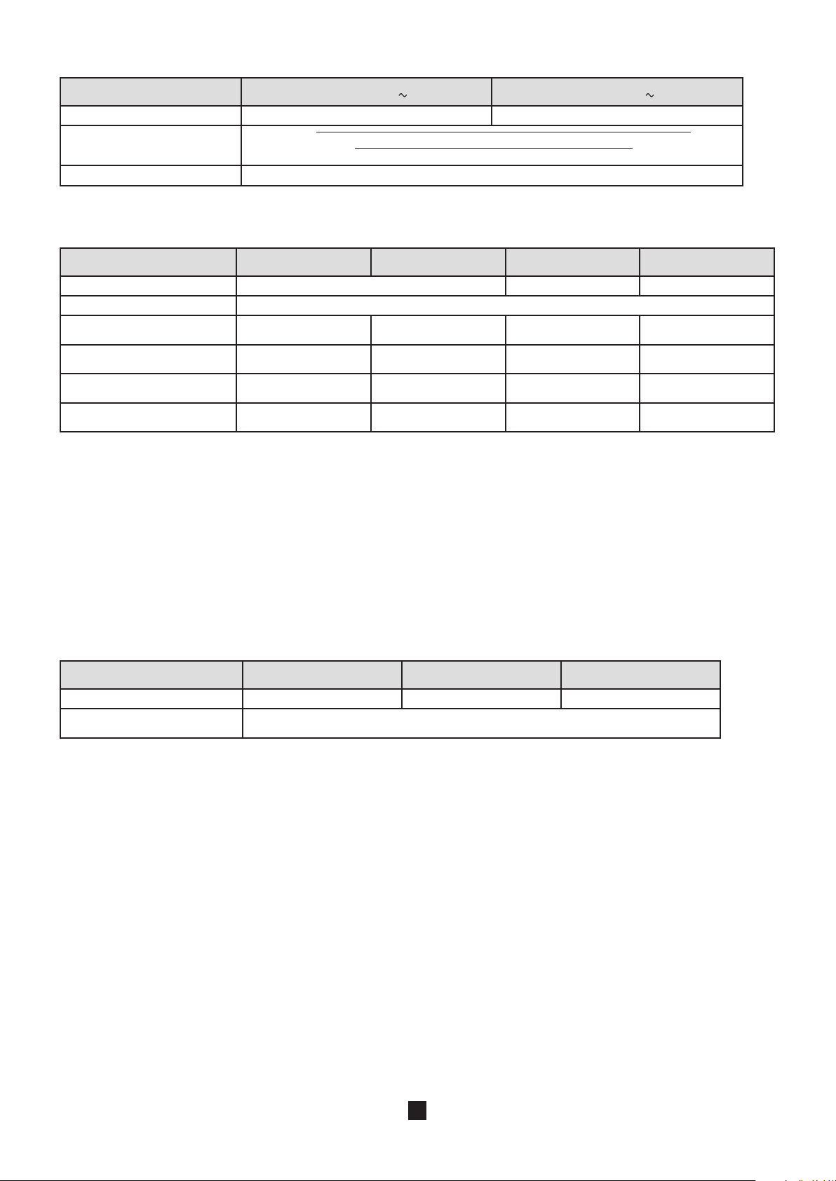
Calculation of the fault voltage if there is a short-circuit, UFk:
Measurement range 0.2 - 399.9 V 400 - 550 V
Resolution 0.1 V 1 V
Intrinsic uncertainty
= √ (Intrinsic uncertainty sur la mesure de tension si U
+ (Intrinsic uncertainty sur la mesure de boucle)²
est utilisé)²
MEAS
Operating frequency 15.3 to 70 Hz
Characteristics in non-tripping mode:
Measurement range 0.20 - 1.99 W 2.00 - 39.99 W 40.0 - 399.9 W 400 - 3999 W
Resolution 0.01 W 0.1 W 1 W
RMS measurement current choice of 6. 9. or 12 mA
Intrinsic uncertainty on the impedance measurement
7
Intrinsic uncertainty on the
resistive part
Intrinsic uncertainty on the
inductive part
Operating uncertainty on the
impedance measurement
± (15% + 3 ct) ± (5% + 3 ct) ± (5% + 2 ct) ± (5% + 2 ct)
± (15% + 3 ct) ± (10% + 3 ct) ± (5% + 2 ct) ± (5% + 2 ct)
± (15% + 3 ct) ± (10% + 3 ct) ± (5% + 2 ct) ± (5% + 2 ct)
± (20% + 3 ct) ± (12% + 3 ct) ± (12% + 2 ct) ± (5% + 2 ct)
7: There is no measurement of the inductive in L-PE loop part with a low current.
The error is defined for 0,1 ≤ R
/ RN ≤ 10 with RL and RN ≥ 1 W.
L
Duration of the measurement: from 12 to 71 periods, depending on the voltage of the installation and the measured impedance.
Maximum acceptable resistance of the voltage probe: 15 kW.
Accuracy on the probe resistance measurement: ± (10% + 5 digits), resolution 0.1 kW.
If smoothing is activated (SMOOTH mode), the measurement result corresponds to the arithmetic mean of 5 values out of 7 (the
smallest and largest values are omitted). The instability of the intrinsic uncertainty is then halved (±5 digits becomes ±2.5 digits)
and the duration of the measurement is of the order of 30 s.
Characteristics in selective mode:
Measurement range 0.50 - 39.99 W 40.0 - 399.9 W 400 - 3999 W
Resolution 0.01 W 0.1 W 1 W
Intrinsic uncertainty on the re-
sistance measurement
8
± (10% + 10 ct)
8: there is no measurement of the inductive part in selective mode.
Duration of the measurement: from 32 to 72 periods, depending on the voltage of the installation and the measured impedance.
Maximum acceptable resistance of the voltage probe: 15 kW.
Accuracy on the probe resistance measurement: ± (10% + 5 digits), resolution 0.1 kW.
The measurement current corresponds to the test current indicated in the table of characteristics in tripping mode divided by the
ratio R
SEL/RA
avec R
≤ 100. Beyond this, the maximum current, 20 mA peak, is reached.
SEL/RA
8.2.10. TEST OF RESIDUAL CURRENT DEVICE
Particular reference conditions:
Voltage of the installation: 90 to 550 V.
Frequency of the installation: 15.3 to 17.5 Hz and 45 to 65 Hz.
Contact voltage (potential of the protective conductor with respect to the local earth): <5 V.
Resistance of the voltage probe (if used): < 100 W.
Potential of the voltage probe (if used) with respect to the PE: < UL.
Residual leakage current of the installation: zero.
73
Page 74

Limitation of the ranges according to the voltage
Range I
DN
90 to 280 V yes yes yes yes yes yes
10 mA 30 mA 100 mA 300 mA 500 mA 650 mA 1000 mA Variable
yes if ≥ 100 V
and R ≤ 2 W
yes if ≤ 950 mA
280 to 550 V yes yes yes yes yes NO NO yes if ≤ 500 mA
The device makes the check when the TEST key is pressed.
The test current is also limited as a function of the nature of the test signal.
Limitation of the ranges in full-wave mode (
Range I
DN
10 mA 30 mA 100 mA 300 mA 500 mA 650 mA 1000 mA Variable
or
)
Ramp yes yes yes yes yes yes yes yes
Pulse at I
Pulse at 2 x I
Pulse at 5 x I
DN
DN
DN
Limitation of the ranges in half-wave mode (
Range I
DN
yes yes yes yes yes yes yes yes
yes yes yes yes yes NO NO yes if ≤ 500 mA
yes yes yes NO NO NO NO yes if ≤ 200 mA
or
)
10 mA 30 mA 100 mA 300 mA 500 mA 650 mA 1000 mA Variable
Ramp yes yes yes yes yes NO NO yes if ≤ 500 mA
Pulse at I
DN
Pulse at 2 x I
Pulse at 5 x I
DN
DN
yes yes yes yes yes NO NO yes if ≤ 500 mA
yes yes yes NO NO NO NO yes if ≤ 250 mA
yes yes NO NO NO NO NO yes if ≤ 100 mA
Characteristics in pulse mode:
Range I
DN
Nature of the test Determination of U
Test current 0.2 x I
Accuracy on the test current
Maximum duration of application of the test current
DN
+0 -7%
from 32 to 72
periods
9: this current can be adjusted in steps of 0.1 I
10 mA - 30 mA - 100 mA - 300 mA - 500 mA - 650 mA - 1000 mA
Variable (6 to 999 mA)
Tripping test (se-
… 0.5 x I
± 2 mA
Non-tripping test Tripping test
F
9
DN
0.5 x I
DN
+0 -7%
± 2 mA
I
DN
-0 +7%
± 2 mA
1000 or 2000 ms 500 ms 500 ms 40 ms
and must not be less than 2,4 mA. As default, this current is 0.4 IDN.
DN
lective)
2 x I
DN
-0 +7%
± 2 mA
Characteristics in ramp mode:
Range I
DN
Nature of the test Determination of U
Test current 0.2 x I
10 mA - 30 mA - 100 mA - 300 mA - 500 mA - 650 mA - 1000 mA
Variable (6 to 999 mA)
Tripping test
0.9573 x IDN x k / 28
… 0.5 x I
DN
F
10
DN
Accuracy on the test current +0 -7% ± 2 mA -0 +7% ± 2 mA
Maximum duration of applica-
tion of the test current
Accuracy on the indication of the
tripping current
from 32 to 72 periods
-
4600 ms to 50 and 60 Hz
4140 ms to 16.6 Hz
-0 +7% + 3.3 % I
DN
Resolution de 0.1 mA up to 400 mA
and 1 mA thereafter
Tripping test
5 x I
-0 +7%
± 2 mA
11
± 2 mA
DN
10: can be parameterized by the user.
11: k is between 9 and 31. The waveform so generated goes from 0.3 I
of 200 ms (180 ms at 16.66Hz).
74
to 1.06 IDN in 22 steps of 3.3% IDN each having a duration
DN
Page 75

Characteristics of the trip time (TA) :
Pulse mode Ramp mode
Measurement range 5.0 - 399.9 ms 400 - 500 ms 10.0 - 200.0 ms
Resolution 0.1 ms 1 ms 0.1 ms
Intrinsic uncertainty ± 2 ms ± 2 ms
Operating uncertainty ± 3 ms ± 3 ms
DN
) :
F
x Z
(or RE) if the test is done at 2x IDN.
LPE
Characteristics of the fault voltage calculation (U
Calculation formula: I
DN
x Z
(or RA or ZA) and 2 x I
LPE
Measurement range 5.0 - 70.0 V
Resolution 0.1 V
Intrinsic uncertainty ± (10% + 10 ct)
8.2.11. CURRENT MEASUREMENT
Particular reference conditions:
Peak factor = 1,414
DC component< 0.1 %
Frequency: 15.3 to 17.5 Hz and 45 to 65 Hz.
For the measurement of I
, the intrinsic uncertainty is increased by 5%.
SEL
Characteristics with the MN77 clamp:
Transformation ratio: 1000 / 1
Measurement range 5.0 - 399.9 mA 0.400 - 3.999 A 4.00 - 19.99 A
Resolution 0.1 mA 1 mA 10 mA
Intrinsic uncertainty ± (2% + 5 ct) ± (1.5% + 2 ct) ± (1.2% + 2 ct)
When a voltage is connected between the L and PE terminals, the device synchronizes to the frequency of this voltage, allowing
current measurements from 1 mA.
Characteristics with the C177 clamp:
Transformation ratio: 1000 / 1
Measurement range 5.0 - 399.9 mA 0.400 - 3.999 A 4.00 - 19.99 A
Resolution 0.1 mA 1 mA 10 mA
Intrinsic uncertainty ± (2% + 5 ct) ± (1.5% + 2 ct) ± (1.2% + 2 ct)
When a voltage is connected between the L and PE terminals, the device synchronizes to the frequency of this voltage, allowing
current measurements from 0.5 mA.
Characteristics with the C177A clamp:
Transformation ratio: 10 000 / 1
Measurement range 0.020 - 3.999 A 4.00 - 39.99 A 40.0 - 199.9 A
Resolution 1 mA 10 mA 100 mA
Intrinsic uncertainty ± (1.5% + 2 ct) ± (1% + 2 ct) ± (1% + 2 ct)
When a voltage is connected between the L and PE terminals, the device synchronizes to the frequency of this voltage, allowing
current measurements from 5 mA.
75
Page 76

8.2.12. DIRECTION OF PHASE ROTATION
Particular reference conditions:
Three-phase network.
Voltage of the installation: 20 to 550 V.
Frequency: 15.3 to 17. 5 Hz and 45 to 65 Hz.
Acceptable level of amplitude unbalance: 20%.
Acceptable level of phase unbalance: 10%.
Acceptable level of harmonics (voltage): 10%.
Characteristics:
The phase order is «positive» if rotation L1-L2-L3 is clockwise.
The phase order is «negative» if rotation L1-L2-L3 is anticlockwise.
The three voltages are measured (see the characteristics in §8.2.1) and indicated as U12, U23 and U31.
8.2.13. POWER MEASUREMENTS
Particular reference conditions:
Sinusoidal voltage and current signals: cosj = 1.
Voltage ≥ 10 V.
Current ≥ 0.1 A (for the C177A clamp).
Frequency: 15.3 to 17.5 Hz and 45 to 65 Hz.
No DC component.
Measurement range 5 - 3999 W 4.00 - 39.99 kW
40.0 - 110.0 kW
40.0 - 330.0 kW
12
Resolution 1 W 10 W 100 W
Intrinsic uncertainty ± (2% + 5 ct) ± (2% + 2 ct) ± (2% + 2 ct)
12: full scale is 110 kW (550V x 200A) in single-phase and 330 kW in three-phase.
8.2.14. POWER FACTOR
Particular reference conditions:
Voltage of the installation: 10 to 550 V.
Current: 0.1 to 200 A.
Measurement range (±) 0.2 - 0.49 (±) 0.50 - 1.00
Resolution 0.01
Intrinsic uncertainty ± (2% + 2 ct) ± (1% + 2 ct)
If the power is zero, the power factor is indeterminate.
The power factor is, by definition, unsigned. But it is given a sign to indicate whether the load is inductive (+ sign) or capacitive
(- sign). The sign is determined by the phase lead or lag between the voltage and the current.
8.2.15. HARMONICS
Particular reference conditions:
Signal without inter-harmonics, of which the fundamental is stronger than the other harmonic components and than the DC
component.
Frequency of the fundamental: 16.66 Hz, 50 Hz, or 60 Hz ± 0.05 Hz.
Peak factor of the signal ≤ 4.
For the C177A clamp: RMS signal greater than 10 V or 1 A.
76
Page 77

Characteristics:
Characteristics of voltage display
Characteristics of current display
Stability of the current and voltage display ± 2 ct
Domain of use Harmonics of orders 1 to 50
Measurement range for the harmonic factor 0.2 - 399.9 %
Detection threshold for the harmonic factor 0.1 %
Measurement range in THD-F and THD-R 0.2 - 100 %
Resolution for the harmonic factor, THD-F and THD-R 0.1%
Intrinsic uncertainty on the RMS value and the harmonic
factor
Intrinsic uncertainty on the THD-F and THD-R 10 ct
Method and definitions:
Determination of harmonics: Cooley-Tukey FFT algorithm on 16 bits
Sampling frequency: 256 times the frequency of the fundamental
Filtering window: rectangular, 4 periods
THD-F: Total distortion referred to the fundamental of the signal.
THD-R: Total distortion referred to the RMS value of the signal (also called DF: distortion factor).
10 to 550 V, the display range being determined by the value of the
1 to 200 A, the display range being determined by the value of the
n=50
Σ
√
THD-F =
n=2
H
1
strongest harmonic component.
strongest harmonic component.
Factor > 10% and order < 13: 5 ct
Factor <10% and order < 13: 10 ct
Factor > 10% and order > 13: 10 ct
Factor > 10% and order > 13: 15 ct
Hn²
n=50
H
²
n
Σ
√
THD-R =
n=2
R[RMS]
8.3. VARIATIONS IN THE RANGE OF USE
8.3.1. VOLTAGE MEASUREMENT
Quantities of influence Limits of the range of use
Temperature -10 … + 55 °C 1 %/10 °C ± 1 ct 2 %/10 °C + 2 ct
Relative humidity 10 … 85 % RH at 45°C 2 % 3 % + 2 ct
Supply voltage 8.4 … 10 V 0.1% or 1 ct 0.5% + 2 ct
Frequency 15.3 … 450 Hz 0.5% 1% + 1 ct
Series mode rejection in AC 0 … 500 V
50/60Hz series mode rejection in DC 0 … 500 V
Common mode rejection in 50/60Hz AC 0 … 500 V
dc 50 dB 40 dB
ac 50 dB 40 dB
ac 50 dB 40 dB
Variation of the measurement
Typical Maximum
77
Page 78

8.3.2. INSULATION MEASUREMENT
Quantities of influence Limits of the range of use
Variation of the measurement
Typical Maximum
Temperature -10 … + 55 °C 1 %/10 °C ± 1 ct 2 %/10 °C + 2 ct
Relative humidity 10 … 85 % RH at 45°C 2 % 3 % + 2 ct
Supply voltage 8.4 … 10 V 0.25% or 2 ct 2% + 2 ct
Ranges 50 V and 100 V
R ≤ 100 MW : 2 V
R > 100 MW : 0,7 V
50/60Hz AC voltage superposed on the
test voltage (U
)
N
Ranges 250 V and 500 V
R ≤ 100 MW : 6 V
R > 100 MW : 2 V
1% 5% + 2 ct
Ranges 500 V and 1000 V
R ≤ 100 MW : 10 V
R > 100 MW : 3 V
Capacitance in parallel on the resistance
to be measured
0 … 5 µF @ 1 mA
0 … 2 µF @ 2000 MW
1%
1%
1% + 1 ct
10% + 5 ct
8.3.3. RESISTANCE AND CONTINUITY MEASUREMENT
Quantities of influence Limits of the range of use
Variation of the measurement
Typical Maximum
Temperature -10 … + 55 °C 1 %/10 °C ± 1 ct 2 %/10 °C + 2 ct
Relative humidity 10 … 85 % RH at 45°C 2 % 3 % + 2 ct
Supply voltage 8.4 … 10 V 0.25% or 1 ct 1% + 2 ct
50/60Hz AC voltage superposed on the
test voltage
ac 0,5% 1% + 2 ct
0.5 V
8.3.4. 3P EARTH MEASUREMENT
Quantities of influence Limits of the range of use
Variation of the measurement
Typical Maximum
Temperature -10 … + 55 °C 1 %/10 °C ± 1 ct 2 %/10 °C + 2 ct
Relative humidity 10 … 85 % RH at 45°C 2 % 3 % + 2 ct
Supply voltage 8.4 … 10 V 0.25% or 1 ct 1% + 1 ct
Voltage in series in the voltage measurement loop (S-E)
Fundamental = 16.6/50/60Hz + odd
15 V (R
25 V (RE > 40 W)
≤ 40 W)
E
0.5% or 10 ct
2% + 50 ct
2% + 2 ct
harmonics
Voltage in series in the current injection
loop (H-E)
Fundamental = 16.6/50/60Hz + odd
15 V (R
25 V (RE > 40 W)
≤ 40 W)
E
0.5% or 10 ct
2% + 50 ct
2% + 2 ct
harmonics
Current loop rod resistance (R
Voltage loop rod resistance (R
) 0 to 15 kW 0.3% 1% + 2 ct
H
) 0 to 15 kW 0.3% 1% + 2 ct
S
78
Page 79

8.3.5. CURRENT MEASUREMENT
Quantities of influence Limits of the range of use
Variation of the measurement
Typical Maximum
Temperature -10 … + 55 °C 1 %/10 °C ± 1 ct 2 %/10 °C + 2 ct
Relative humidity 10 … 85 % RH at 45°C 2 % 3 % + 2 ct
Supply voltage 8.4 … 10 V 0.1% or 2 ct 0.5% + 2 ct
Frequency
15.3 … 45 Hz
45 … 450 Hz
50/60Hz series mode rejection in AC 0 … 500 V
ac 50 dB 40 dB
1%
0.5%
1% + 1 ct
1.5% + 1 ct
8.3.6. EARTH MEASUREMENT ON LIVE CIRCUIT, LOOP AND SELECTIVE EARTH
Quantities of influence Limits of the range of use
Variation of the measurement
Typical Maximum
Temperature -10 … + 55 °C 1 %/10 °C ± 1 ct 2 %/10 °C + 2 ct
Relative humidity 10 … 85 % RH at 45°C 2 % 3 % + 2 ct
Supply voltage 8.4 … 10 V 0.5% or 2 ct 2% + 2 ct
Network frequency of the installation
tested
Network voltage of the installation tested
Phase difference between the internal load
and the measured impedanceor inductance of the measured impedanceor L/R
ratio of the measured impedance
Resistance in series with the voltage probe
(earth on live circuit only)
Contact voltage (U
) 0 … 50 V
C
99 to 101% of the nominal
frequency
85 to 110% of the nominal
voltage
0 …20°
or 0 … 400 mH
or 0 … 500 ms
0 … 15 kW
0.1% or 1 ct 0.1% + 1 ct
0.1% or 1 ct 0.1% + 1 ct
1%/10° 1%/10°
Negligible
(taken into account in the
intrinsic uncertainty)
(taken into account in the
intrinsic uncertainty)
Negligible
(taken into account in the
intrinsic uncertainty)
(taken into account in the
intrinsic uncertainty)
Negligible
Negligible
8.3.7. TEST OF RESIDUAL CURRENT DEVICE
Quantities of influence Limits of the range of use
Variation of the measurement
Typical Maximum
Temperature -10 … + 55 °C 1 %/10 °C ± 1 ct 2 %/10 °C + 2 ct
Relative humidity 10 … 85 % RH at 45°C 2 % 3 % + 2 ct
Supply voltage 8.4 … 10 V 0.1% or 1 ct 0.5% + 2 ct
Network frequency of the installation
tested
Network voltage of the installation tested
99 to 101% of the nominal
frequency
85 to 110% of the nominal
voltage
0.1% or 1 ct 0.1% + 1 ct
0.1% or 1 ct 0.1% + 1 ct
8.3.8. DIRECTION OF PHASE ROTATION
No quantity of influence
79
Page 80

8.3.9. POWER
Quantities of influence Limits of the range of use
Variation of the measurement
Typical Maximum
Temperature -10 … + 55 °C 1 %/10 °C ± 1 ct 2 %/10 °C + 2 ct
Relative humidity 10 … 85 % RH at 45°C 2 % 3 % + 2 ct
Supply voltage 8.4 … 10 V 0.1% or 1 ct 0.5% + 2 ct
Network frequency of the installation
tested
Network voltage of the installation
tested
Power factor
99 to 101% of the nominal
frequency
85 to 110% of the nominal
voltage
0.50 … 1.00 at 45…65 Hz
0.20 … 0.49 at 45…65 Hz
0.50 … 1.00 at 15.3…17.5 Hz
0.20 … 0.49 at 15.3…17.5 Hz
0.1% or 1 ct 0.1% + 1 ct
0.1% or 1 ct 0.1% + 1 ct
0.5%
1.5%
2%
4%
1% + 2 ct
3% + 2 ct
2.5% + 2 ct
5% + 2 ct
8.3.10. VOLTAGE AND CURRENT HARMONICS
The quantities of influence and the associated variations are the same as for voltage measurements and current measurements,
respectively.
8.4. INTRINSIC UNCERTAINTY AND OPERATING UNCERTAINTY
The C.A. 6116 installation tester complies with standard IEC-61557, which requires that the operating uncertainty, called B, be
less than 30%.
In insulation, B = ± ( |A| + 1,15
with A = intrinsic uncertainty
E1 = influence of the reference position ± 90°.
E2 = influence of the supply voltage within the limits indicated by the manufacturer
E3 = influence of the temperature between 0 and 35°C.
√ E
² + E2² + E3² )
1
In continuity measurement, B = ± ( |A| + 1,15
In loop measurement, B = ± ( |A| + 1,15
√ E
² + E2² + E3² )
1
√ E
² + E2² + E3² + E6² + E7² + E8² )
1
with E6 = influence of the phase angle from 0 to 18°.
E7 = influence of the network frequency from 99 to 101% of the nominal frequency.
E8 = influence of the network voltage from 85 to 110% of the nominal voltage.
In earth measurement, B = ± ( |A| + 1,15
√ E
² + E2² + E3² + E4² + E5² + E7² + E8² )
1
with E4 = influence of the interference voltage in series mode (3 V at 16.6, 50, 60, and 400 Hz)
E5 = influence of the resistance of the rods from 0 to 100 x RA but ≤ 50 kW.
In test of residual current device, B = ± ( |A| + 1,15
√ E
² + E2² + E3² + E5² + E8² )
1
with E5 = influence of the resistance of the probes within the limits indicated by the manufacturer.
8.5. POWER SUPPLY
The device is powered by a 9.6 V, 4 Ah rechargeable NiMH battery pack.
This has many advantages:
long life between charges with limited bulk and weight,
the possibility of recharging your battery rapidly,
a very small memory effect: you can recharge your battery even if it is not fully discharged, without reducing its capacity,
protection of the environment through the absence of polluting materials such as lead and cadmium.
The NiMH technology allows a limited number of charging/discharging cycles that depends on the conditions of use and the
charging conditions. Under optimum conditions, this number of cycles is 200.
The day before you use your device, check its charge condition. If the battery level indicator shows less than three bars, charge
the device overnight (see §1.2).
The charging time is approximately 5 h.
80
Page 81

To make the most of your battery and extend its effectiveness:
Use only the charger supplied with your device. The use of another charger may prove dangerous!
Charge your device only between 10 and 35°C.
Observe the conditions of use and storage stated in this data sheet.
The mean battery life depends on the type of measurement and on how the device is used. Approximately:
16 h if the automatic switching off function is deactivated,
24 h if the automatic switching off function is activated,
8.6. ENVIRONMENTAL CONDITIONS
Indoor and outdoor use.
Operating range 0 to 55°C and 10% to 85% RH
Specified operating range 13 0 to 35°C and 10% to 75% RH
Range for recharging the battery 10 to 35°C
Range in storage (without battery) -40°C to +70°C and 10% to 90% RH
Altitude <2,000m
Pollution degree 2
13: This range corresponds to the range of the operating uncertainty defined by standard IEC-61557. When the device is used
outside this range, it is necessary to add 1.5%/10°C and 1.5% between 75 and 90% RH to the operating uncertainty.
8.7. MECHANICAL CHARACTERISTICS
Dimensions (L x D x H) 280 x 190 x 128 mm
Weight approximately 2.4 kg
Protection class IP 53 per IEC-60 529 (Ed. 92) if the cover of the USB port is closed, IP 51 if it is open.
IK 04 per IEC-50102 (Ed. 95)
Free fall test Per IEC-61010-1 (Ed. 2 of 2001)
8.8. CONFORMITY TO INTERNATIONAL STANDARDS
The device is in conformity with IEC-61010-1 (Ed. 2 of 2001), 600V, CAT III.
Assigned characteristics: measurement category III, 600V with respect to earth, 550V in differential between the terminals, and
300V, CAT II on the charger input.
The device is in conformity with:
IEC-61557 (Ed. 2 of 2007) parts 1, 2, 3, 4, 5, 6, and 7.
IEC-61557 (Ed. 1 of 2001) part 10.
8.9. ELECTROMAGNETIC COMPATIBILITY (EMC)
The device is in conformity with standard IEC-61326-1 (Ed. 97) + A1 (Ed. 98) + A2 (Ed. 2001).
81
Page 82

9. DEFINITIONS OF SYMBOLS
G
S
Here is a list of the symbols used in this document and on the display unit of the device.
3P earth resistance measurement with 2 auxiliary rods.
AC AC (Alternating Current) signal.
DC DC (Direct Current) signal.
DF Distortion Factor = THD-R.
E E terminal (earth electrode, measurement current return terminal).
FFT harmonic analysis of a signal (Fast Fourier Transform).
selective residual current device, specific to Austria.
H H terminal (measurement current injection terminal in 3P earth measurement).
Hz Hertz: indicates the frequency of the signal.
I current.
current in phase 1 of a three-phase network.
I
1
current in phase 2 of a three-phase network.
I
2
current in phase 3 of a three-phase network.
I
3
assigned differential operating current of the RCD to be tested.
I
DN
RCD tripping current of the residual current device.
I
a
Ik short-circuit current between the L and N, L and PE, N and PE, or L and L terminals.
IT Type of link to earth defined in standard IEC-60364-6.
current flowing in the earthing resistance to be measured in selective earth measurement on live circuit.
I
SEL
L L terminal (phase).
Li inductance in the L-N or L-L loop.
LS inductance in the L-PE loop.
N N terminal (neutral).
P active power, P = U . I . PF.
PE PE terminal (protective conductor).
PF power factor (cosj for sinusoidal signal).
PIT Permanent Insulation Tester.
phase difference of the current with respect to the voltage.
j
R mean resistance calculated from R+ and R-.
R+ resistance measured with a positive current flowing from terminal W to terminal COM.
R- resistance measured with a negative current flowing from terminal W to terminal COM.
R± resistance measured alternately with a positive current, then a negative current.
resistance of the accessories subtracted from the measurement (compensation of the measurement leads).
R
D
RCD acronym designating a Residual Current Device or switch.
earth resistance in earth measurement on live circuit.
R
A
selective earth resistance in selective earth measurement on live circuit.
R
ASEL
earth resistance connected to the E terminal.
R
E
resistance of the rod connected to the H terminal.
R
H
resistance in the L-N loop.
R
L-N
resistance in the L-PE loop.
R
L-PE
RMS Root Mean Square: root-mean-square value of the signal, the square root of the mean of the squares of the signals.
resistance in the N-PE loop.
R
N-PE
nominal resistance in insulation measurement RN = UN/1mA.
R
N
resistance of the auxiliary rod in earth measurement on live circuit.
R
PI
resistance of protective conductor PE.
R
PE
resistance of the rod connected to the S terminal.
R
S
S terminal S (acquisition of measurement potential for the earth resistance calculation).
selective residual current device.
TA effective trip time of the residual current device.
THD-F level of harmonic distortion referred to the fundamental.
82
Page 83

THD-R harmonic distortion factor referred to the RMS value of the signal.
TN type of link to earth defined in standard IEC-60364-6.
TT type of link to earth defined in standard IEC-60364-6.
voltage between phases 1 and 2 of a three-phase network.
U
12
voltage between phases 2 and 3 of a three-phase network.
U
23
voltage between phases 3 and 1 of a three-phase network.
U
31
contact voltage between conducting parts when they are touched simultaneously by a person or an animal (IEC-
U
C
fault voltage appearing during a fault condition between accessible conducting parts (and/or external conducting
U
F
fault voltage, in the event of a short-circuit, according to Swiss standard SEV 3569.
U
Fk
UFk = Ik x ZA = U
voltage measured between terminals H and E.
U
H-E
conventional maximum contact voltage (IEC-61557).
U
L
voltage measured between the L and N terminals.
U
L-N
voltage measured between the L and PE terminals.
U
L-PE
nominal test voltage in insulation measurement, generated between the MW and COM terminals.
U
N
voltage measured between the N and PE terminals.
U
N-PE
voltage between the PE conductor and the local earth measured when the user presses the TEST key.
U
PE
reference voltage for calculation of the short-circuit current.
U
REF
voltage measured between the S and E terminals.
U
S-E
earth impedance in earth measurement on live circuit.
Z
A
impedance in the loop between the phase and the protective conductor.
Z
S
impedance in the loop between the phase and the neutral or between two phases (line loop impedance).
Z
i
impedance in the L-N loop.
Z
L-N
impedance in the L-PE loop.
Z
L-PE
61557).
parts) and the reference frame ground (IEC-61557).
x ZA/ZS.
REF
83
Page 84

10. MAINTENANCE
IEC 61010
IEC 61557
MADE IN FRANCE
IEC 61010
IEC 61557
MADE IN FRANCE
IEC 61010
IEC 61557
MADE IN FRANCE
For maintenance, use only the spare parts specified. The manufacturer cannot be held liable for any accident that occurs
following a repair not performed by its customer service department or by an approved repairer.
10.1. CLEANING
Disconnect anything connected to the device and set the switch to OFF.
Use a soft cloth, dampened with soapy water. Rinse with a damp cloth and dry rapidly with a dry cloth or forced air. Do not use
alcohol, solvents, or hydrocarbons.
10.2. REPLACING THE BATTERY
The battery of this device is specific: it has precisely matched protection and safety elements. Replacement of the battery by a
model other than the one specified may result in damage to equipment or bodily injury by explosion or fire.
To keep the device safe, replace the battery only with the original model.
Replacement procedure:
1. Disconnect anything connected to the device and set the switch to OFF.
2. Turn the two quarter-turn screws of the battery compartment cover using a tool, then remove the battery compartment
cover.
3. Turn the device over while holding the battery as it slides out of its compartment.
4. Disconnect the battery connector without pulling on the wires.
5. Connect the new battery. The connector is polarized to prevent connection errors.
6. Place the battery in its compartment and arrange the wires to that they do not protrude.
84
Page 85

SET UP
OFF
SET UP
OFF
OK
7. Put the battery compartment cover back in place and screw the two quarter-turn screws back.
8. Charge the new battery fully before using the device.
9. If the battery remained disconnected for more than 5 minutes, you may have to reprogram the date and time of the device
(see §5).
Attention : Whenever the battery is disconnected, even if it is not replaced, it must be charged fully. This is so that the device
will know the charge condition of the battery (this information is lost when it is disconnected).
10.3. RESETTING THE DEVICE
If the device crashes, it can be reset, like a PC.
Set the switch to ZS (RA/SEL.).
Press the 3 keys indicated below simultaneously.
10.4. METROLOGICAL CHECK
Like all measuring or testing devices, the instrument must be checked regularly.
This instrument should be checked at least once a year. For checks and calibrations, contact one of our accredited metrology laboratories (information and contact details available on request), at our Chauvin Arnoux subsidiary or the branch in your country.
10.5. REPAIR
For all repairs before or after expiry of warranty, please return the device to your distributor.
85
Page 86

11. WARRANTY
Except as otherwise stated, our warranty is valid for twelve months starting from the date on which the equipment was sold.
Extract from our General Conditions of Sale provided on request.
The warranty does not apply in the following cases:
Inappropriate use of the equipment or use with incompatible equipment;
Modifications made to the equipment without the explicit permission of the manufacturer’s technical staff;
Work done on the device by a person not approved by the manufacturer;
Adaptation to a particular application not anticipated in the definition of the equipment or not indicated in the user’s manual;
Damage caused by shocks, falls, or floods.
86
Page 87

12. TO ORDER
Installation Tester Model C.A 6116 ...................................................................................................................... Cat. #2138.01
Delivered with:
one carrying bag
one power cord
one hand strap
carrying strap for meter
ICT data export software on CD-ROM
USB cable (1.8m)
one 3-Pin voltage lead with US plug
one 3-Pin lead with color-coded (red, blue & green) stackable safety banana plugs
one, set of 3, color-coded test probes (red, blue & green)
one, set of 3, color-coded alligator clips (red, blue & green)
one standard ground/earth kit
one, set of 2, color-coded leads {3m} (red/black 4mm straight, 4mm right angle)
one remote test probe
5 user manuals on CD (one per language)
5 safety sheets (one per language)
12.1. ACCESSORIES
Test Kit for 3-Pole (3-Point) Testing (150 ft) .............................................................................................................Cat. #2135.35
Test Kit for 4-Pole (4-Point) Testing (300 ft) .............................................................................................................Cat. #2135.36
Test Kit for 4-Pole (4-Point) Testing (500 ft) .............................................................................................................Cat. #2135.37
Test Kit for 3-Pole (3-Point) Testing ......................................................................................................................... Cat. #2135.38
AC Current Probe Model C177A..............................................................................................................................Cat. #2138.52
AC Current Probe Model MN77 ...............................................................................................................................Cat. #2138.53
Continuity Pole ......................................................................................................................................................... Cat. #2138.54
Wrist strap ................................................................................................................................................................ Cat. #2138.59
12.2. REPLACEMENT PARTS
Probe - Remote test probe ......................................................................................................................................Cat. #2118.97
Battery - 9.6V NiMH battery .....................................................................................................................................Cat. #2140.19
Cable - 5 ft USB cable .............................................................................................................................................Cat. #2140.46
Lead - 3-Pin voltage lead with US plug ..................................................................................................................Cat. #2138.55
Lead - 3-Pin lead with color-coded (red, blue & green) stackable safety banana plugs .........................................Cat. #2138.56
Lead - Set of 2, color-coded leads {3m} (red/black 4mm straight, 4mm right angle) .............................................Cat. #2138.57
Strap - Carrying strap for meter ............................................................................................................................... Cat. #2138.58
Clips - Set of 3, color-coded alligator clips (red, blue & green) ...............................................................................Cat. #2140.70
Probe - Set of 3, color-coded test probes (red, blue & green).................................................................................Cat. #2140.71
Power cord (1.8m) .................................................................................................................................................... Cat. #5000.27
Carrying case ...........................................................................................................................................................Cat. #5000.28
Screen protection film .............................................................................................................................................. Cat. #5000.29
87
Page 88

11 - 2009
Code 691945A02 - Ed. 1
DEUTSCHLAND - Chauvin Arnoux GmbH
Straßburger Str. 34 - 77694 Kehl / Rhein
Tel: (07851) 99 26-0 - Fax: (07851) 99 26-60
ESPAÑA - Chauvin Arnoux Ibérica S.A.
C/ Roger de Flor, 293 - 1a Planta - 08025 Barcelona
Tel: 90 220 22 26 - Fax: 93 459 14 43
ITALIA - Amra SpA
Via Sant’Ambrogio, 23/25 - 20050 Macherio (MI)
Tel: 039 245 75 45 - Fax: 039 481 561
ÖSTERREICH - Chauvin Arnoux Ges.m.b.H
Slamastrasse 29/2/4 - 1230 Wien
Tel: 01 61 61 9 61-0 - Fax: 01 61 61 9 61-61
SCANDINAVIA - CA Mätsystem AB
Box 4501 - SE 18304 TÄBY
Tel: +46 8 50 52 68 00 - Fax: +46 8 50 52 68 10
http://www.chauvin-arnoux.com
190, rue Championnet - 75876 PARIS Cedex 18 - FRANCE
Tél. : +33 1 44 85 44 85 - Fax : +33 1 46 27 73 89 - info@chauvin-arnoux.fr
Export : Tél. : +33 1 44 85 44 38 - Fax : +33 1 46 27 95 59 - export@chauvin-arnoux.fr
SCHWEIZ - Chauvin Arnoux AG
Moosacherstrasse 15 - 8804 AU / ZH
Tel: 044 727 75 55 - Fax: 044 727 75 56
UNITED KINGDOM - Chauvin Arnoux Ltd
Waldeck House - Waldeck Road - Maidenhead SL6 8BR
Tel: 01628 788 888 - Fax: 01628 628 099
MIDDLE EAST - Chauvin Arnoux Middle East
P.O. BOX 60-154 - 1241 2020 JAL EL DIB (Beirut) - LEBANON
Tel: (01) 890 425 - Fax: (01) 890 424
CHINA - Shanghai Pu-Jiang - Enerdis Instruments Co. Ltd
3 F, 3 rd Building - N° 381 Xiang De Road - 200081 SHANGHAI
Tel: +86 21 65 21 51 96 - Fax: +86 21 65 21 61 07
USA - Chauvin Arnoux Inc - d.b.a AEMC Instruments
200 Foxborough Blvd. - Foxborough - MA 02035
Tel: (508) 698-2115 - Fax: (508) 698-2118
 Loading...