

Page 1
n T ACHYMÈTRE
n T ACHOMETER
n DREHZAHLMESSER
n T ACHIMETRO
n T ACÓMETRO
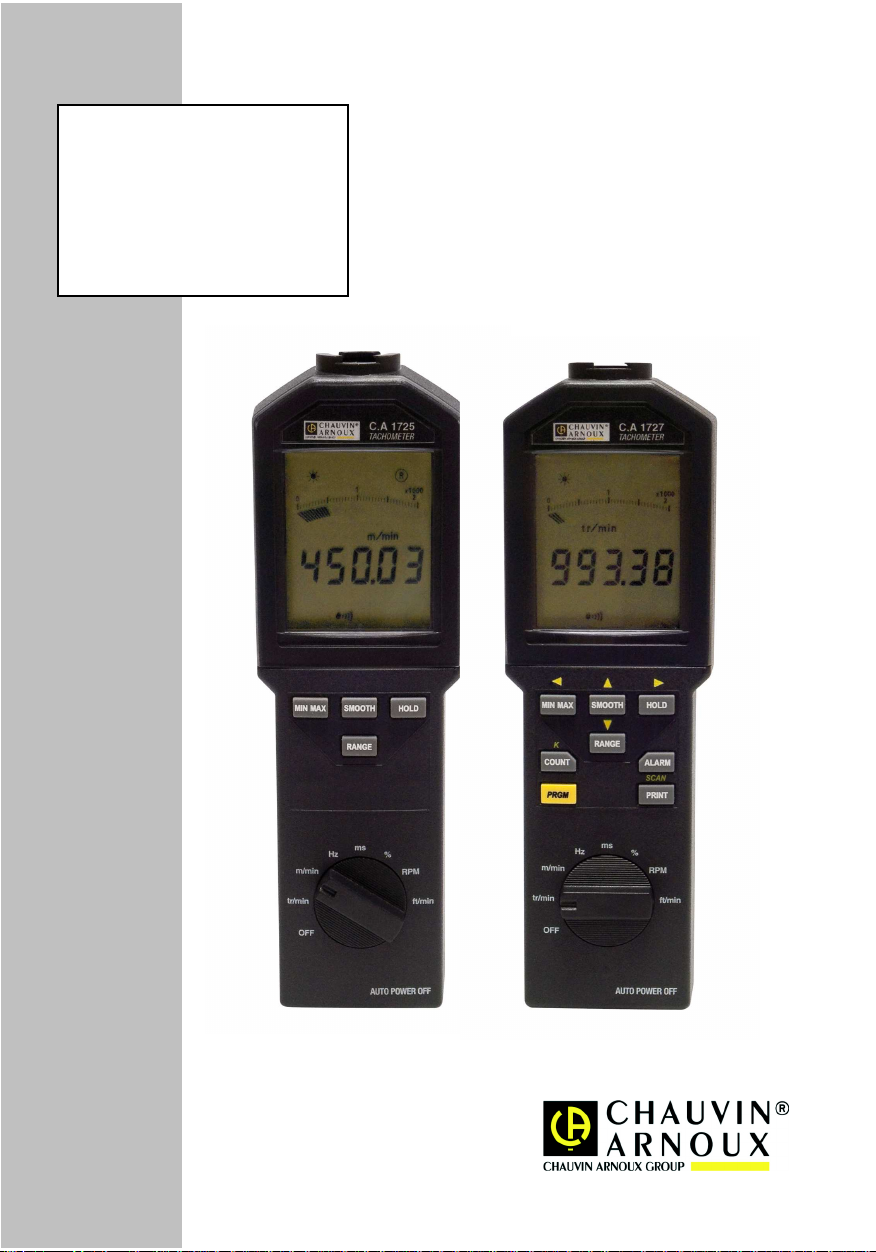
C.A 1725
C.A 1727
FRANÇAIS
ENGLISH
DEUTSCH
ITALIANO
ESPAÑOl
Notice d’utilisation
User's Manual
Bedienungsanleitung
Libreto d'Istruzioni
Manual de Instrucciones
11
Page 2
Signification des symboles utilisés sur l’appareil.
ATTENTION, risque de DANGER!
Consulter la notice de fonctionnement à chaque fois que ce symbole est rencontré.
Ce marquage garantit la conformité aux directives européennes «Basse Tension» et
«Compatibilté Electromagnétique» (73/23/CEE).
Dans l’Union Européenne, ce produit fait l’objet d’un tri sélectif des déchets pour le recyclage
des matériels électriques et électroniques conformément à la directive WEEE 2002/96/EC.
Vous venez d'acquérir un Tachymètre C.A 1725 / C.A 1727 et nous vous remercions de votre
confiance.
Pour obtenir le meilleur service de votre appareil :
• Lire attentivement ce mode d'emploi.
• Respecter les précautions d'emploi.
PRÉCAUTIONS D’EMPLOI
En mesure sans contact mécanique :
Avant d’utiliser le tachymètre, vérifier que la fenêtre frontale de visée est parfaitement propre. La
distance de détection minimale est de 1cm, il faut cependant éviter la proximité immédiate de toute pièce
en mouvement qui pourrait être dangereuse pour l’opérateur et pour l’appareil.
En mesure avec contact mécanique :
Eloigner au maximum les mains de la pièce en mouvement.
Ne pas exercer d'appui trop important car la mesure risque d'être erronée par freinage de la pièce en
mouvement.
Pour les mesures en bout d'arbre, se mettre le plus possible dans l'axe de l'arbre.
En mesure avec entrée externe :
L'utilisation de la prise externe nécessite le respect des règles sur les liaisons des appareils de
comptage, concernant les parasites industriels.
Emploi de fils blindés reliés à une masse non soumise aux rejets de commutations de systèmes de
puissance.
Les parasites reçus ne devront pas dépasser l'amplitude de l'hystérésis fixée dans l'appareil (250 mV).
L'entrée externe est limitée à un mode commun maximum de 50 volts.
ATTENTION :
La masse électrique de la prise capteur externe est commune à la masse électrique de la sortie
numérique USB.
2
Page 3

English ...........................................................................................................................................30
Deutsch.........................................................................................................................................58
Italiano ...........................................................................................................................................86
Español..........................................................................................................................................114
SOMMAIRE
1. INTRODUCTION .........................................................................4
2. DESCRIPTION............................................................................4
2.1 TACHYMÈTRE.......................................................................................................................... 4
2.2 AFFICHEUR .............................................................................................................................. 7
3. UTILISATION...............................................................................9
3.1 MESURES SANS CONTACT .................................................................................................... 9
3.2 MESURES A VEC CONT ACT ..................................................................................................... 9
3.3 MESURES A VEC ENTRÉE EXTERNE ...................................................................................... 10
4. FONCTIONNEMENT ............................................................... 12
4.1 UNITÉS DE MESURE............................................................................................................... 12
4.2 ENREGISTREMENT MIN/MAX ................................................................................................. 13
4.3 MAINTIEN DE LA V ALEUR NUMÉRIQUE A L ’AFFICHAGE ...................................................... 14
4.4 LISSAGE DE LA MESURE ...................................................................................................... 15
4.5 CHOIX MANUEL DE GAMME.................................................................................................. 15
4.6 COMPTAGE(C.A1727 uniquement) ....................................................................................... 16
4.7 ENREGISTREMENT DE MESURES (C.A 1727 uniquement) ................................................... 16
4.8 ALARMES (C.A 1727 uniquement) ....................................................................................... 17
4.9 PROGRAMMATION (C.A 1727 uniquement).......................................................................... 18
4.10 EXPLOIT ATION DES DONNÉES SUR PC (C.A 1727 uniquement).......................................... 22
5. ENTRETIEN............................................................................. 23
6. CARACTÉRISTIQUES............................................................. 24
6.1 CARACTÉRISTIQUES GÉNÉRALES ....................................................................................... 24
6.2 CARACTÉRISTIQUES MÉTROLOGIQUES .............................................................................. 25
6.3 CARACTÉRISTIQUES DU CAPTEUR ...................................................................................... 27
6.4 CARACTÉRISTIQUES DE L’ADAPT A TEUR ET SES EMBOUTS .............................................. 28
7. POUR COMMANDER .............................................................. 29
33
Page 4
1. INTRODUCTION
Spécialement conçu pour des applications industrielles, les tachymètres C.A 1725 et C.A 1727 mesurent
à distance, ou par contact, la vitesse de rotation de toute pièce en mouvement.
En plus des fonctions classiques, les tachymètres CHAUVIN-ARNOUX offrent de multiples possibiltés:
- lecture directe de la mesure
- mesure de période, de fréquence, de rapport cyclique, de vitesse linéaire
- mesure par capteur externe
- fonctions spéciales : smooth, range, hold...
- double affichage, numérique 100 000 points et bargraphe.
Paramétrable et équipé d‘une liaison USB, le C.A 1727, associé à son logiciel spécifique, offre de larges
possibilités de mesures, d‘acquisition, de traitement et d‘exploitation des données.
2. DESCRIPTION
2.1 T ACHYMÈTRE
1 Capteur optique
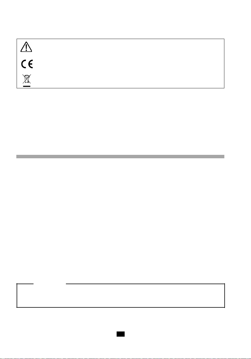
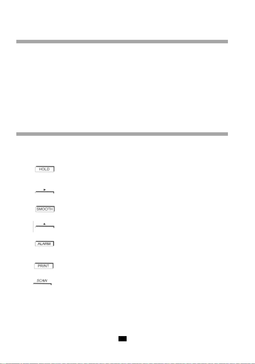
2 Touche
- mémorisation de la dernière valeur numérique affichée.
- inhibition de l‘arrêt automatique.
T ouche sur le C.A 1727 seul :
- en programmation : déplacement de la sélection du chiffre actif ou de la virgule vers la droite.
3 Touche =>
- lissage des mesures.
Touche sur le C.A 1727 seul :
- en programmation : incrémentation du chiffre actif.
4 Touche sur C.A 1727 seul :
- mise en service des alarmes sonores et visuelles.
- programmation des seuils d‘alarmes.
5 Touche sur C.A 1727 seul :
- commande d‘enregistrement des mesures en mémoire.
Touche sur C.A 1727 seul :
- programmation de la cadence d‘enregistrement des mesures en mémoire.
6 Connecteur de sortie USB sur C.A 1727 seul.
7 Connecteur pour entrée externe.
8 Commutateur rotatif.
4
Page 5
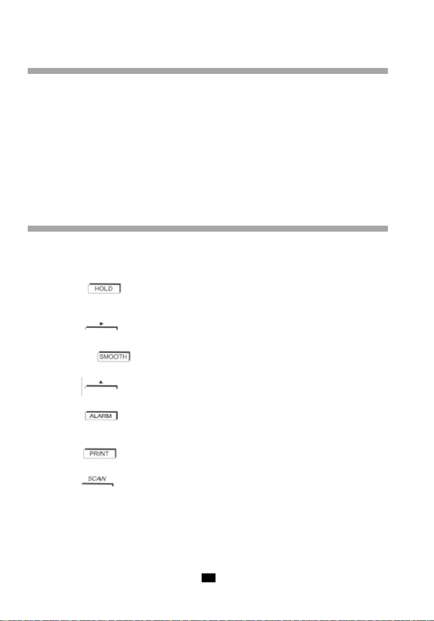
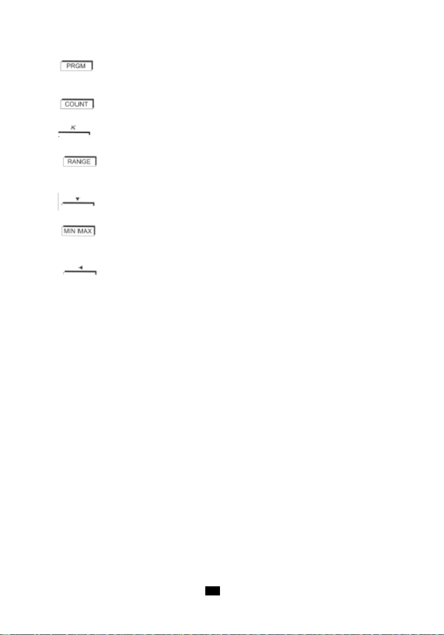
9 Touche sur C.A 1727 seul :
- programmation.
- initialisation de la mémoire programme.
10 Touche sur C.A 1727 seul :
- compteur d‘évènement.
Touche sur C.A 1727 seul :
- programmation du facteur d‘échelle : coéfficient K.
11 Touche =>
- changement de gamme manuel ou automatique.
- élargissement du domaine de mesure en basse fréquence.
Touche sur C.A 1727 seul :
- en programmation : décrémentation du chiffre.
12 Touche :
- enregistrement des minima et maxima.
- inhibition du buzzer.
Touche sur le C.A 1727 seul :
- en programmation : déplacement de la sélection du chiffre actif ou de la virgule vers la gauche.
55
Page 6

6
Page 7

2.2 AFFICHEUR
1 Mode programmation sur C.A 1727 seul.
2 Seuil bas franchi sur C.A 1727 seul.
3 Coefficient K de fin d'échelle sur C.A 1727 seul.
4 Fonction seuil bas sur C.A 1727 seul.
5 Fonction d'écriture en mémoire sur C.A 1727 seul.
6 Fonction seuil haut sur C.A 1727 seul.
7 Seuil haut franchi sur C.A 1727 seul.
8 Fonction cadencement d'enregistrement des mesures en mémoire sur C.A 1727 seul.
9 Emission ou réception en cours sur C.A 1727 seul.
10 Témoin clignotant de fonctionnement du capteur infrarouge.
11 Valeur de la fin d'échelle du bargraphe (de 2 à 200 x 1 000).
12 Affichage analogique par bargraphe.
13 Pointe de flèches symbolisant le dépassement de fin d'échelle.
14 Vitesse de rotations - Revolutions per minute (en anglais)
15 Revolutions : comptage de tours (en anglais) sur C.A 1727 seul.
16 mètre par minute : vitesse linéaire.
17 Hertz : fréquence.
18 Affichage numérique sur 5 chiffres.
19 Mesures en valeurs lissées.
20 Affichage figé de la dernière mesure.
21 Enregistrement momentanément arrêté.
22 Appareil en fonctionnement permanent.
23 Témoin d'usure de pile.
24 Enregistrement des MIN / MAX.
25 Témoin du buzzer actif.
26 Lecture de la mémoire des MAX.
27 Etendue de mesure élargie à 0,1 Hz.
28 Lecture de la mémoire des MIN.
29 Inhibition du changement de gamme automatique.
30 Fonction de comptage sur C.A 1727 seul.
31 Milliseconde : période.
32 Rapport cyclique.
33 · ft/min : feet per minute - vitesse linéaire (en anglais).
· tr/min : tour par minute - vitesse de rotation.
34 Echelle fixe graduée.
35 Mesure par prise externe.
36 Emetteur optique en action.
77
Page 8

8
Page 9

3. UTILISATION
3.1 MESURES SANS CONT ACT
La mesure sans contact s'effectue par le capteur optique intégré à l'appareil. Ce capteur placé dans la
partie avant de l'appareil, se compose d'un émetteur de lumière infrarouge modulée en fréquence.
Avant toute mesure, il faut préparer la cible tournante dont on désire connaître la vitesse.
Vérifier que la surface visée ne présente pas de réflexions parasites qui pourraient être comptées en
plus des impulsions issues de l'adhésif réfléchissant. Pour cela, avant de coller l'adhésif qui servira à
la mesure, faire tourner la cible et s'assurer en visant celle-ci que la mesure indique toujours ---. Si ce
n'est pas le cas, il faut recouvrir toute la surface de la cible d'un support noir mat.
Lorsque la cible est correcte, coller une bande d'adhésif réfléchissant sur celle-ci, suivant l'axe formé
par un rayon le plus long possible. Pour les petites cibles la surface recouverte par le ruban adhésif
devra être inférieure à 50% de la surface totale de la partie tournante.
Mettre en rotation la cible, viser celle-ci avec la partie avant de l'appareil, s'assurer que le symbole de
mesure correcte clignote régulièrement.
La distance entre le capteur et la cible doit être comprise entre 1 et 50cm.
L'angle de mesure de 30° (15° de part et d'autre de l'axe de la cible) permet une visée confortable.
Lors de mesures de faibles vitesses, de très petits mouvements de l'appareil peuvent engendrer des
instabilités de mesure : dans ce cas, il est recommandé de poser l'appareil sur un support stable. Un
écrou placé sous le boîtier de l'appareil est prévu pour sa fixation sur un pied.
3.2 MESURES A VEC CONT ACT
L'adaptateur mécanique et ses 3 embouts permettent la mesure par contact en bout d'arbre ou sur une
surface en mouvement linéaire.
Il se place devant la fenêtre de visée du capteur optique et accepte l'un des 3 embouts suivants :
- un cône en élastomère dont la pointe finale permet la mesure en bout d'arbre (diamètre
minimum : 5mm).
- un cylindre en élastomère permet la mesure en bout d'arbre plan ou sur des axes
inférieurs à 5mm.
- une roue en élastomère pour la mesure de la vitesse linéaire (1 tour de roue = 0,1m).
L'embout doit être appuyé sur la pièce en mouvement avec une force juste suffisante à son entraînement
sans glissement.
L'adaptateur se fixe sur l'avant du boîtier du tachymètre devant la fenêtre de visée. Un verrouillage
automatique en fin de course assure le maintien en position.
- Montage
Pour fixer l'adaptateur, placer les trois ergots intérieurs de l'adaptateur en regard des trois creux de la
fenêtre de visée du boîtier et tourner dans le sens inverse des aiguilles d'une montre.
- Démontage
Pour le retirer, tirer l'adaptateur vers l'extérieur jusqu'à libération des pattes de verrouillage et tourner
l'ensemble dans le sens des aiguilles d'une montre.
99
Page 10
3.3 MESURES A VEC ENTRÉE EXTERNE
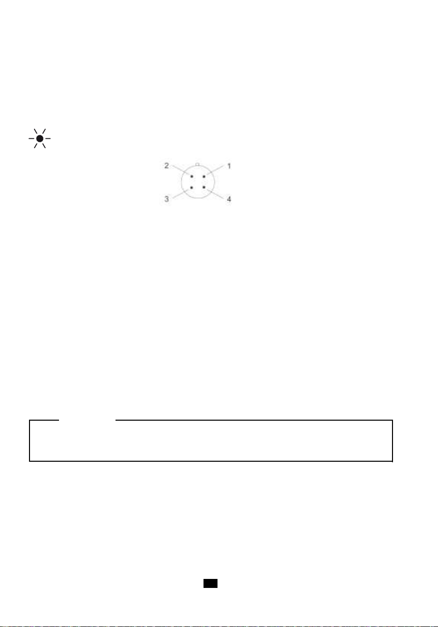
L'appareil possède un connecteur 4 contacts permettant le raccordement à une source extérieure dont
on veut connaître la vitesse, la fréquence, la période, le rapport cyclique…
Afin d'indiquer au tachymètre que la prise de la mesure se fait sur l'entrée externe, il est nécessaire de
court-circuiter les broches 1 et 4.
Le fonctionnement sur entrée externe est indiqué sur l'afficheur par l'extinction du symbole d'émission
et l'affichage de EXT.
Câblage
Connecteur du tachymètre 2- entrée mesure (± 20VC maxi)
vu côté contacts 3- voir ci-dessous
Le raccordement de la broche n°1 à la broche n°3 permet d‘adapter le seuil de déclenchement à la
nature des signaux.
Broches 1 et 3 non connectées
Fonctionnement prévu pour des signaux TTL 0 - 5V
Le seuil de déclenchement est fixé à + 1,1V (à 1kHz).
Pour éviter les problèmes dus aux bruits souvent présents en milieu industriel, le seuil possède une
hystérésis de 250mV.
Broches 1 et 3 connectées
Fonctionnement prévu pour des signaux symétriques par rapport à la masse.
Cette fonction permet la mesure directe à partir d‘un capteur magnétique à réluctance variable ou de la
sortie d‘un alternateur.
Le seuil de déclenchement est fixé à 300mV (à 1kHz) avec une hystérésis de 250mV. La résiduelle de
bruit superposée au signal à mesurer doit être inférieure à 250mV pour ne pas parasiter la mesure au
franchissement du seuil.
ATTENTION :
La masse électrique de la prise capteur externe est commune à la masse électrique de la sortie
numérique USB.
1- masse
4- à court-circuiter avec broche n°1
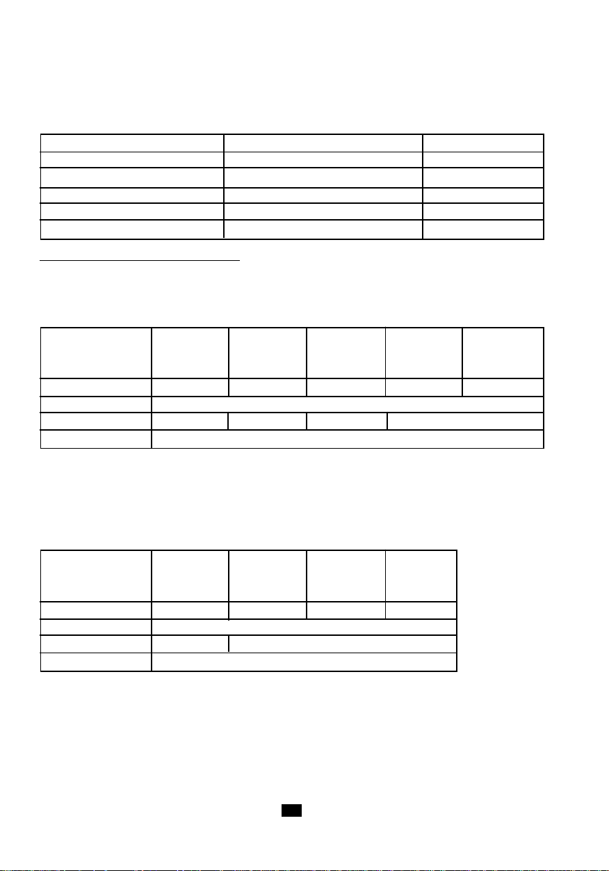
L’utilisation de l’entrée externe est nécessaire pour la mesure des signaux lents à partir de 0,1Hz. Le
tableau ci-après résume les caractéristiques de cette entrée.
10
Page 11
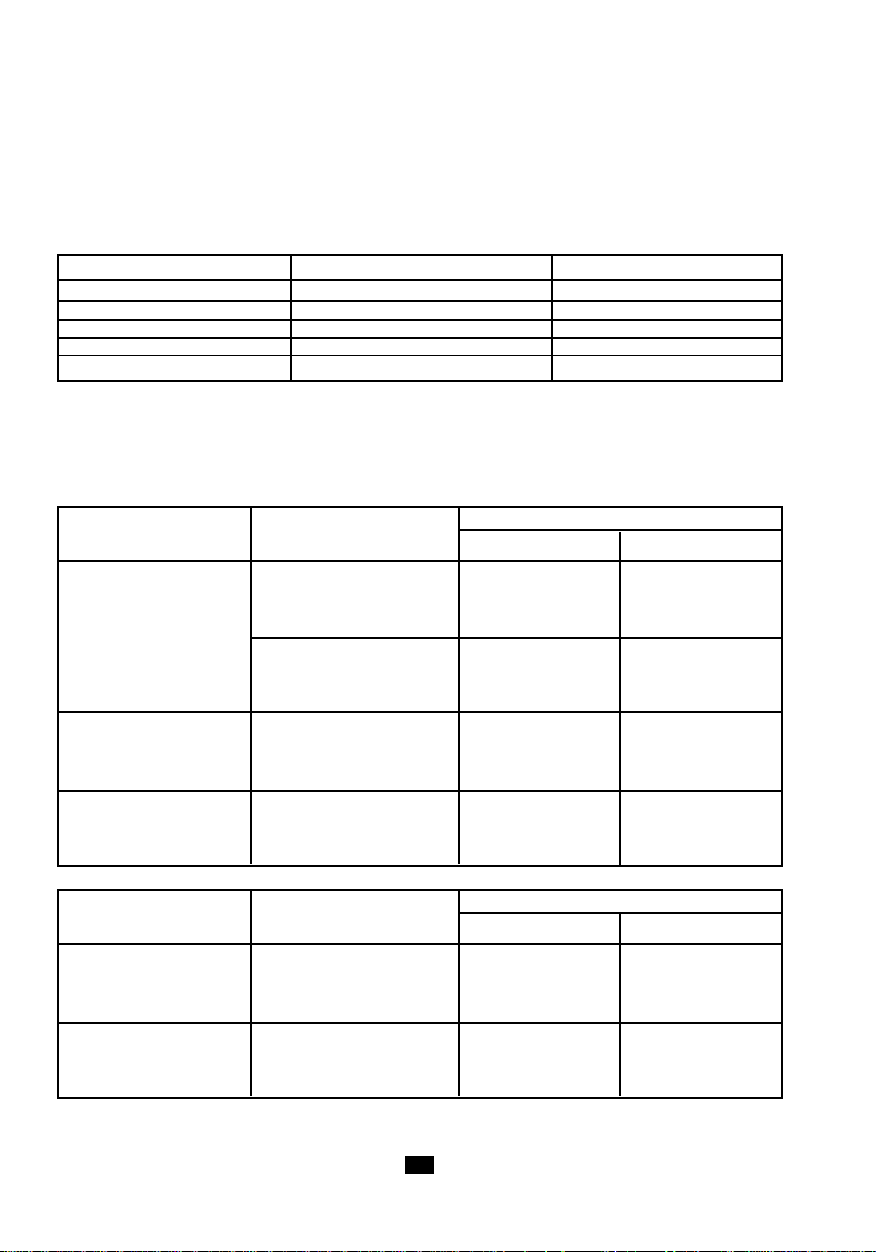
Gamme de fréquence de
mesure
de 1 Hz à 10 kHz
de 0,1 Hz à 10 kHz en gamme élargie
Fonctions disponibles idem capteur optique
Précision idem capteur optique
Impédance d’entrée
≥
75 KΩ
Mode signaux symétriques
Seuils
300 mV ± 80 mV à1 kHz600 mV ± 160 mV
à 10 kHz
Hystérésis
250 mV ± 80 mV
Mode signaux TTL
Seuils
1,1 V ± 150 mV à 1 kHz
2,2 V ± 300 mV à 10 kHz
Hystérésis
250 mV ± 80 mV
Tension maximale
±
20 V crête
Surcharge admissible (1
seconde)
250 V eff.
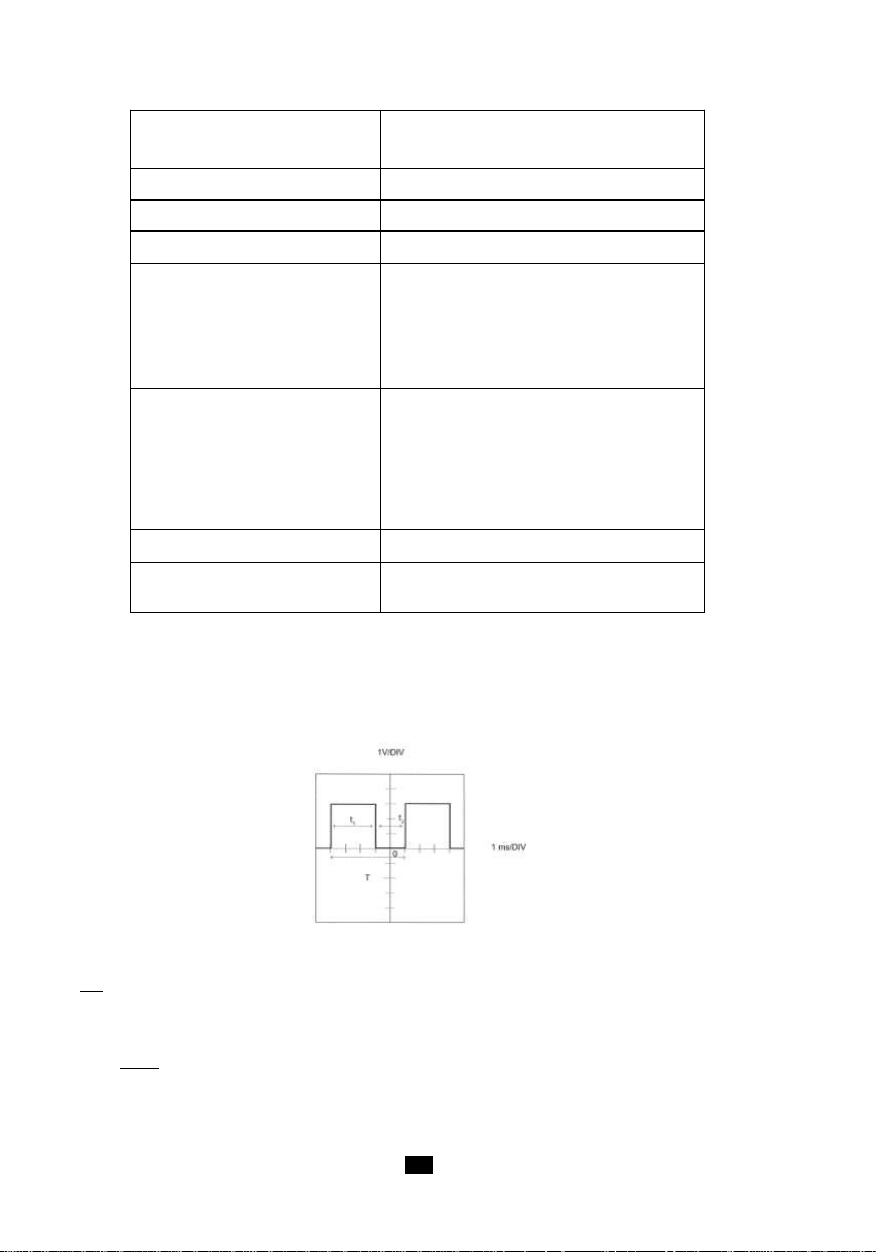
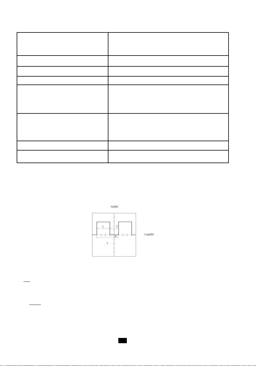
Exemple de Mesure de RAPPORT CYCLIQUE sur ENTRÉE EXTERNE
L‘utilisation de l‘entrée externe nécessite le raccordement du connecteur FRB fourni avec l‘appareil à
la source du signal à mesurer, puis le branchement de ce connecteur sur la prise marquée EXT.
Supposons avoir un signal du type de celui montré dans la figure suivante :
Ici la fréquence du signal est donnée par la formule :
1
f =
T
T = 5 x 1ms = 5ms
1
donc f = = 200Hz
5.10
-3
1111
Page 12

Le rapport cyclique est donné par :
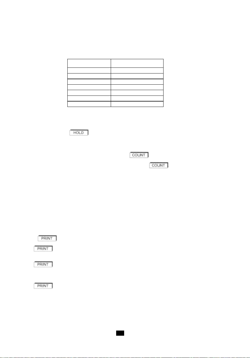
Fonction Affichage
tr/mn ou RPM 60.000 à 99999
m/mn (K = 0.1) 6.0000 à 99999
ft/mn (K = 0.328) 19.680 à 99999
Hz 1.0000 à 9999.9
Période (ms) 0.1000 à 999.99
Rapport cyclique % 0.1 à 99.9
Compteur 0 à 99999
t
Duty =
ou en %. Duty % = x 100
Ici nous avons :
1
t1 + t
2
t
1
t1 + t
2
3
Duty % = x 100 = 60%
3 + 2
Pour effectuer cette mesure avec les tachymètres C.A 1725 ou C.A 1727, il faut :
1 vérifier l’amplitude du signal entrant dans l’appareil. Ceci permet de déterminer le seuil à fixer. Ici
l’amplitude est supérieure à +1,1V, donc il ne faut pas raccorder les broches 1 et 3 de la prise
FRB entre elles.
2 mettre en route le tachymètre en amenant le commutateur rotatif sur «%».
3 l’afficheur donne directement le résultat mentionné ci-dessus.
Si l’afficheur n’indique rien, il faut vérifier que le signal à mesurer a bien une amplitude supérieure au
seuil de déclenchement.
4. FONCTIONNEMENT
4.1 UNITÉS DE MESURE
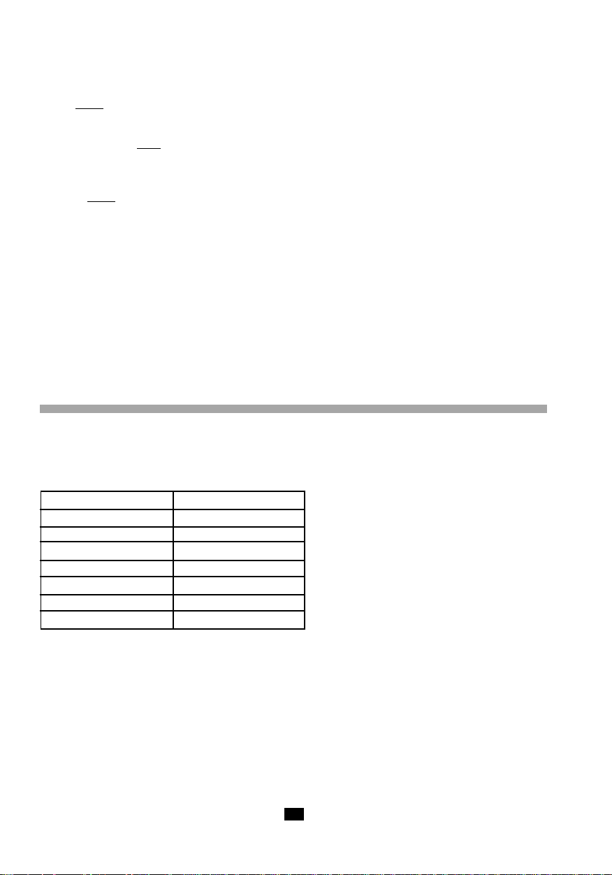
Le tableau ci-dessous indique la capacité d‘affichage pour chaque fonction.
En mesure élargie à 0,1Hz par l‘entrée Ext, les valeurs minimales sont divisées par 10.
Fonction Marche/Arrêt :
A défaut de sa suppression à la mise en marche (voir ci-dessous), un arrêt automatique de l‘appareil
s‘effectue si il n‘y a pas eu pendant 5 minutes :
- appui sur une touche,
- ou manoeuvre du commutateur rotatif,
- ou interrogation de la sortie numérique.
Avant l‘arrêt automatique, le tachymètre émet un bip sonore.
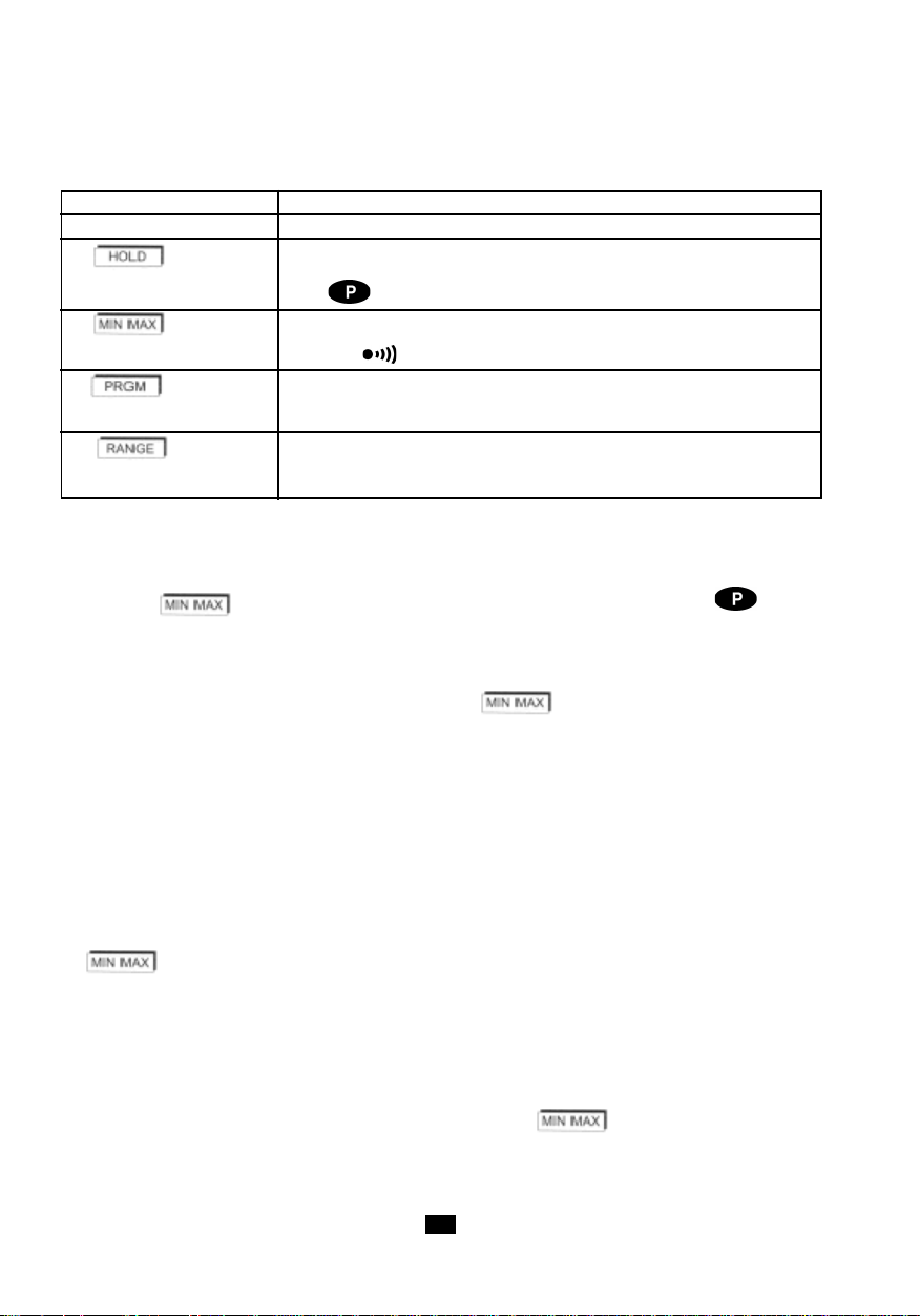
Fonctions spéciales :
Les fonctions spéciales suivantes sont obtenues lorsqu‘une touche est maintenue appuyée à la mise
en marche de l‘appareil :
12
Page 13
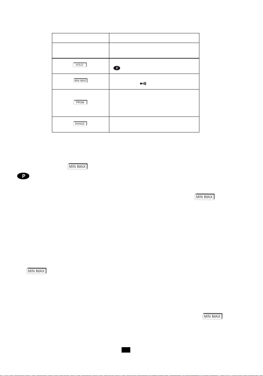
TOUCHE FONCTION
Aucune touche
pressée
Mise en marche pour 5 minutes
Mise en marche permanente
apparaît sur l’afficheur
Mise en marche sans buzzer
le symbole n’apparaît donc pas
Initialisation de toutes les valeurs
contenues dans la mémoire
programme.
L’afficheur indique " Init ".
Mesure jusqu’à 0,1 Hz
SLOW s’allume sur l’afficheur
4.2 ENREGISTREMENT MIN / MAX
La fonction enregistrement permet la mémorisation des valeurs minimales et maximales des mesures.
Un appui sur la touche place l‘appareil en mode enregistrement. Les symboles RECORD et
sont affichés. La fonction d‘arrêt automatique est inhibée.
Valeur MIN
Initialement, la valeur mémorisée est OL (OVER LOAD). Dès l‘appui sur la touche la valeur
affichée est mémorisée dans le registre MIN.
A chaque fois qu‘une mesure est inférieure à celle contenue dans le registre, elle est transférée dans
le registre MIN et un bip sonore à 1kHz est émis.
Valeur MAX
La valeur mémorisée au départ est zéro. Une valeur de mesure supérieure à celle contenue dans le
registre entraîne sa mise à jour.
A chaque modification du contenu de la mémoire MAX, un bip sonore à 2kHz est émis.
Lecture des mémoires MIN/MAX
L‘affichage des valeurs contenues dans les registres MIN et MAX s‘effectue par appuis successifs
sur .
L‘affichage circulaire indique successivement le MAX, le MIN et la valeur de la mesure courante.
L‘enregistrement se poursuit pendant la lecture tandis que le bargraphe indique la mesure instantanée.
NB : si la fonction „SMOOTH“ est activée, les MAX et MIN sont déterminés à partir des valeurs filtrées.
Arrêt de la fonction enregistrement MIN/MAX
L‘arrêt de la fonction enregistrement est obtenu, soit par un appui long sur la touche , soit
par rotation du commutateur.
Remarque : La fonction MIN/MAX n‘est pas disponible en mode comptage.
1313
Page 14
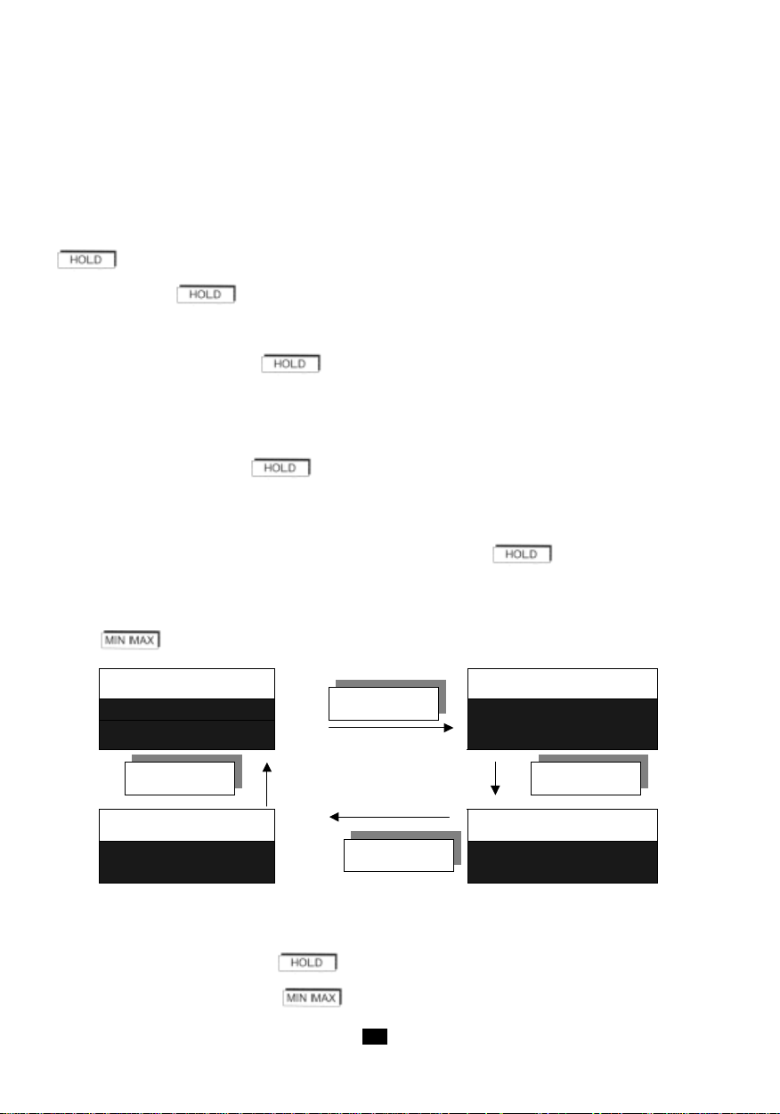
4.3 MAINTIEN DE LA V ALEUR NUMÉRIQUE À L‘AFFICHAGE
Mémoire HOLD
Mémoire MAX
HOLD
RECORD PAUSE MAX RECORD PAUSE
Mesure instantanée
Mémoire MIN
RECORD PAUSE
MIN RECORD
PAUSE
MIN MAX MIN MAX
MIN MAX
MIN MAX
Par appui bref sur la touche HOLD (hors mode programmation).
L‘appui sur HOLD permet de figer l‘affichage numérique sur la dernière mesure affichée tandis que le
bargraphe continue d‘indiquer la valeur instantannée de la mesure. L‘affichage indique HOLD. Un
nouvel appui sur la touche HOLD restaure l‘affichage des mesures instantannées et HOLD disparaît de
l‘afficheur.
en mode d‘enregistrement „MIN/MAX“
Lorsque la touche est pressée quand RECORD est affiché :
- les symboles HOLD et PAUSE s‘affichent.
- l‘enregistrement est stoppé et les valeurs contenues dans les mémoires MIN et MAX sont les
dernières valeurs avant .
- l‘afficheur numérique indique la valeur de la dernière mesure, ou encore, la valeur MIN ou MAX
si l‘appareil était en relecture de celles-ci.
- le bargraphe continue d‘indiquer la mesure courante.
Un nouvel appui sur la touche poursuit l‘enregistrement des MIN et des MAX :
- les symboles HOLD et PAUSE restent affichés.
- l‘afficheur indique la mesure en cours ou le contenu de la mémoire MIN/MAX en relecture.
- l‘appareil est à nouveau en fonction MIN/MAX mais les mémoires n‘ont pas été réinitialisées et
elles contiennent les valeurs MIN et MAX présentes avant le .
Quand les symboles HOLD et RECORD - PAUSE sont affichés, il est encore possible de visualiser, de
façon circulaire, les valeurs des mémoires et de la mesure instantanée par des appuis brefs sur la
touche .
Le bargraphe indique toujours la valeur de la mesure courante.
Quel que soit l‘affichage en cours :
- un appui bref sur la touche rétablit l‘enregistrement sans réinitialiser les mémoires.
- un appui long sur la touche stoppe l‘enregistrement.
14
Page 15
Application :
Lorsque le tachymètre est utilisé dans un endroit où la lecture de l‘afficheur est difficile ou impossible,
l‘utilisation de la fonction HOLD couplée avec l‘enregistrement MIN/MAX permet de conserver en mémoire
le minimum et le maximum atteints.
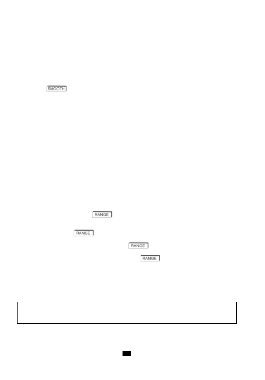
4.4 LISSAGE DE LA MESURE
Une pression sur la touche déclenche le lissage de la mesure (SMOOTH affiché). La valeur
numérique indiquée est alors le résultat d‘une moyenne glissante calculée sur les 10 dernières mesures
(soit environ 5 secondes).
Le bargraphe indique toujours la mesure instantanée.
En enregistrement MIN MAX, si le symbole SMOOTH est affiché, les valeurs enregistrées sont celles
filtrées (lissées).
La mise en fonction ou l‘arrêt du mode SMOOTH pendant un enregistrement MIN MAX annule les valeurs
MIN et MAX déjà stockées.
Remarque : la fonction SMOOTH n‘a pas d‘action en fonction comptage.
4.5 CHOIX MANUEL DE GAMME
A la mise en marche, ou lors d‘un changement de fonction, l‘appareil sélectionne automatiquement la
gamme de mesure la mieux appropriée. Chaque fonction possède 4 ou 5 gammes, exceptée la fonction
rapport cyclique (2 gammes).
En fonctionnement automatique, l‘afficheur numérique a une capacité d‘affichage de 20000 points et la
fin de l‘échelle du bargraphe peut prendre les valeurs : 2 - 20 - 200 - 2000 - 20000 et 200000.
En mode automatique, l‘afficheur numérique passe sur une gamme supérieure quand 20000 points sont
atteints.
Un premier appui bref (< 2s) sur la touche fige la gamme de mesure en cours. RANGE
apparaît sur l‘afficheur. L‘indicateur numérique a alors une capacité d‘affichage de 100000 points.
Chaque nouvelle appui sur la touche incrémente les deux affichages (bargraphe et
numérique) sur la gamme supérieure. Arrivé à la gamme la plus haute (20000 points) la touche
ramène l‘appareil sur la gamme 2.
Pour sortir du mode de changement manuel de gamme, appuyer sur la touche plus de 2
secondes.
Remarque : Si la valeur de la mesure est supérieure à la capacité d‘affichage, l‘afficheur indique OL
et la flèche de dépassement de gamme apparaît à droite du bargraphe.
ATTENTION :
Les fonctions décrites dans les paragraphes suivants ne sont disponibles que sur le C.A 1727.
1515
Page 16
4.6 COMPT AGE (C.A 1727 UNIQUEMENT)
Mode de mesure Mode COUNT
tr / min tr (tour)
m / min m (mètre)
RPM REV (révolution)
ft / min ft (foot)
Hz /
ms /
Duty % /
Pressez la touche COUNT pour placer l‘appareil en mode de comptage d‘évènements. COUNT apparaît
sur l‘afficheur et les unités de mesure sont modifiées (voir tableau ci-après).
Les symboles Hz, ms et % disparaissent. Il n‘y a plus d‘unité de mesure affichée; l‘appareil compte
simplement le nombre d‘impulsions reçues.
Un appui sur la touche stoppe le comptage. Un second appui relance le comptage
momentanément stoppé.
Arrivé à 99999 évènements, l‘affichage passe sur OL.
Pour sortir du comptage, il suffit d‘appuyer sur la touche une deuxième fois. La remise à zéro
du compteur s‘obtient par deux appuis successifs sur la touche .
Remarques :
- En standard, l‘appareil compte des mètres ou des pieds („feet“) avec une définition de mesure
égale à la circonférence de l‘embout utilisé, soit 0,1m ou 0,328ft. Cette définition peut être
modifiée en changeant la valeur de K.
- En mode comptage, les fonctions d‘enregistrement, de changement de gamme et de lissage ne
sont pas disponibles.
4.7 ENREGISTREMENT DE MESURES (C.A 1727 UNIQUEMENT)
La touche permet l‘enregistrement de la valeur affichée.
- avec HOLD :
L‘enregistrement sera la dernière valeur affichée, précédée de HOLD.
- avec enregistrement MIN/MAX :
Lorsque l‘appareil est en mode d‘enregistrement RECORD, MIN ou MAX sur l‘écran, la commande PRINT
enregistre le MIN, le MAX et la mesure courante.
- avec enregistrement MIN MAX + HOLD :
Dans ce mode (symboles RECORD-PAUSE et HOLD affichés), la commande PRINT enregistre les
quatre paramètres suivants :
- la valeur HOLD
- la valeur contenue dans le registre MIN
- la valeur contenue dans le registre MAX
- la valeur de la mesure courante.
16
Page 17
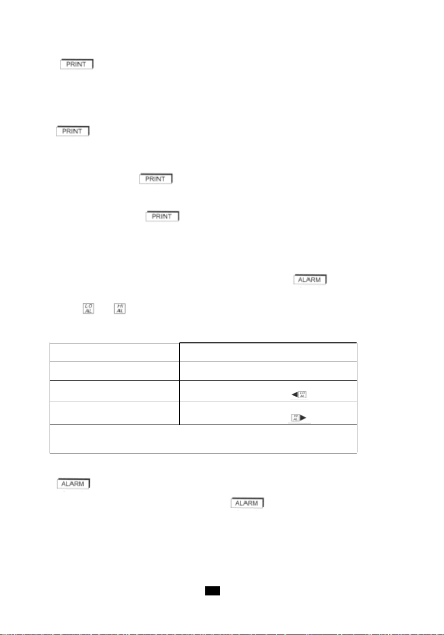
- avec SMOOTH
Mesure numérique > seuil
bas (LO AL)
Aucune action
Mesure numérique < seuil
haut (HI AL)
Aucune action
Mesure numérique < seuil
bas
Buzzer en continu à 1 kHz
Affichage de
Mesure numérique > seuil
haut
Buzzer en continu à 4 kHz
Affichage de
Si la valeur de LO AL est supérieure à HI AL, le fonctionnement est
inversé. Le buzzer se déclenche (2 kHz) dans la zone centrale située
entre les valeurs HI AL et LO AL.
La valeur enregistrée est alors la valeur lissée, quand cette fonction est affichée (SMOOTH).
Pendant toute la durée d‘enregistrement des informations, les symboles PRINT et COM sont affichés.
Lorsque la fonction Scanning est programmée (voir „Intervalle d‘enregistrement“), la pression de la
touche démarre le cycle d‘enregistrement des mesures selon l‘intervalle programmé. Le
symbole SCAN s‘affiche et reste affiché pendant toute la durée du fonctionnement du scanning. PRINT
et COM s‘affichent à chaque émission de données vers la mémoire.
Un second appui sur la touche interrompt le scanning, avec l‘émission des dernières données
et l‘extinction des symboles SCAN, PRINT et COM.
T out nouvel appui sur la touche met en service ou arrête alternativement la fonction.
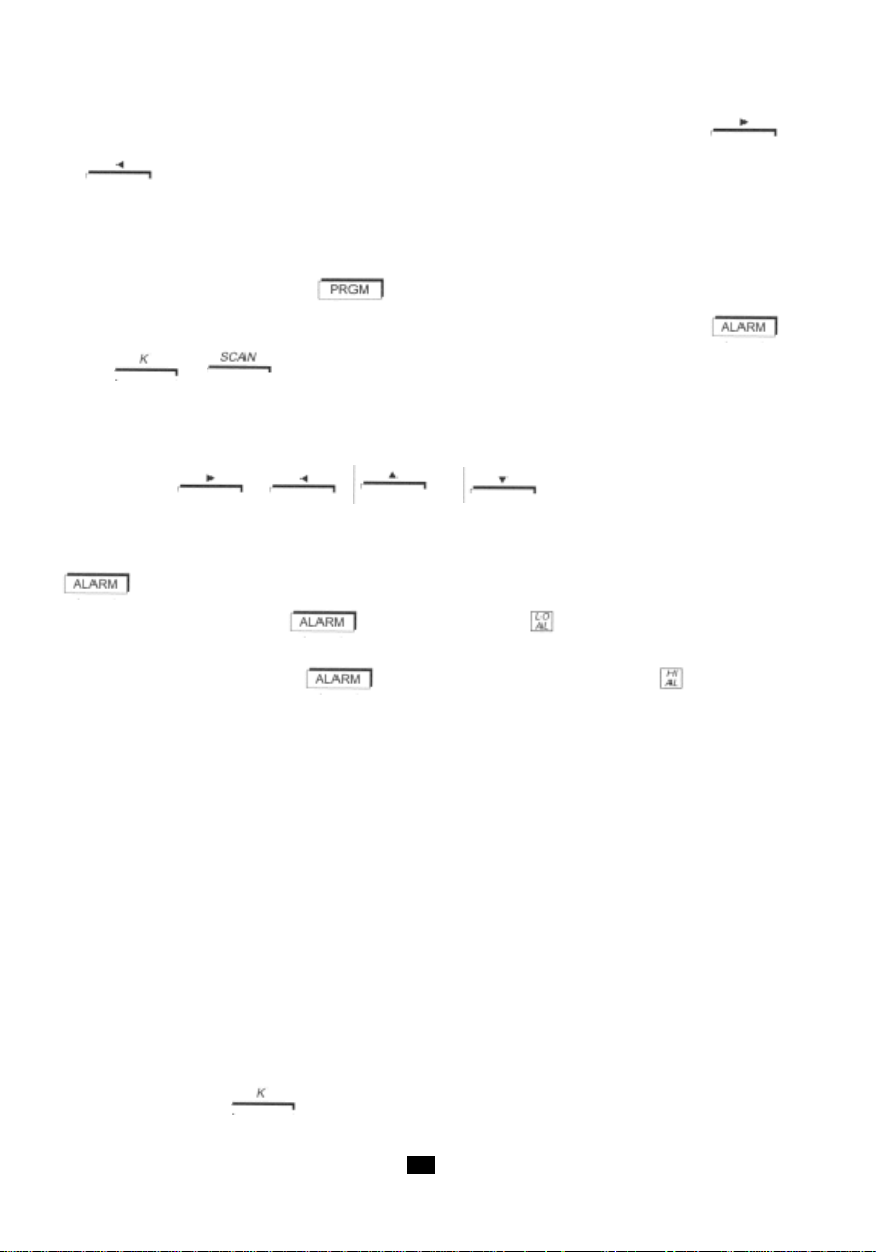
4.8 ALARMES (C.A 1727 UNIQUEMENT)
Lorsque des seuils ont été programmés, un appui bref sur la touche met en service la
détection de franchissement de ces seuils par la mesure.
Les symboles ou , ou les deux, s‘affichent en fonction du type de seuil programmé.
Le fonctionnement est résumé dans le tableau ci-dessous.
Si aucune valeur de seuil n‘a été programmée, un bip sonore est émis lors de l‘appui sur la
touche et cette commande n‘est pas prise en compte.
Pour arrêter la fonction Alarme, appuyez sur la touche une nouvelle fois.
1717
Page 18
4.9 PROGRAMMA TION (C.A 1727 UNIQUEMENT)
L‘appareil dispose de quatre valeurs programmables pour définir :
- un seuil d‘alarme basse LO AL.
- un seuil d‘alarme haute HI AL.
- un coefficient multiplicateur K.
- un intervalle d‘enregistrement SCAN.
Un appui sur la touche met le C.A 1727 en programmation, PRGM s‘affiche. En mode
programmation le C.A 1727 n‘effectue plus de mesure, le bargraphe est éteint, l‘émetteur optique est
arrêté.
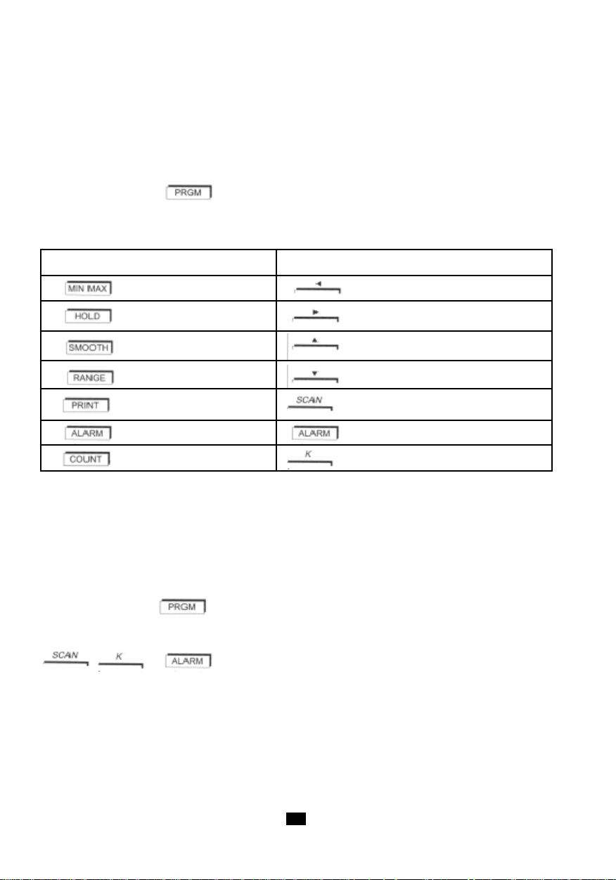
Les fonctions des touches deviennent celles indiquées en jaune au-dessus de chaque touche.
Fonction des touches en mesure Fonction des touches en programmation
Déplacement à gauche
Déplacement à droite
Incrémentation du chiffre actif
Décrémentation du chiffre actif
Programmation du scanning
Programmation des seuils
Programmation du coéfficient K
Mode opératoire
Les explications ci-dessous décrivent la procédure à employer pour programmer les différentes
mémoires du C.A 1727. Ces étapes sont communes à toutes les fonctions : scanning, seuils et
coéfficient K.
Les paragraphes „Seuils d‘alarmes“ à „Intervalle d‘enregistrement“ décrivent les particularités relatives
à chaque fonction.
Avant de mettre le C.A 1727 en programmation, vous devez choisir à l‘aide du commutateur rotatif la
fonction pour laquel vous désirez programmer des valeurs.
Un appui sur la touche entraîne l‘affichage du symbole PRGM, l‘extinction du bargraphe et
l‘affichage de „-----“.
La deuxième étape consiste à choisir la fonction à programmer en appuyant sur la touche
: ; ou .
L‘afficheur numérique indique alors la valeur contenue dans la mémoire ou „-----“ si rien n‘a été
précédemment programmé (cas d‘une programmation ou si la dernière programmation avait inhibée
cette fonction). En même temps, le chiffre (ou tiret) de gauche clignote.
La programmation s‘effectue sur 100000 points (0 à 99999) et il y a 5 positions possibles de la virgule
pour les seuils d‘alarme (la virgule est fixe pour K et l‘intervalle SCAN n‘a pas de virgule).
L‘entrée d‘une valeur en mémoire s‘effectue de la manière suivante :
A/ écriture de tous les chiffres composant la valeur désirée, sans tenir compte de la virgule.
B/ positionnement de la virgule.
18
Page 19
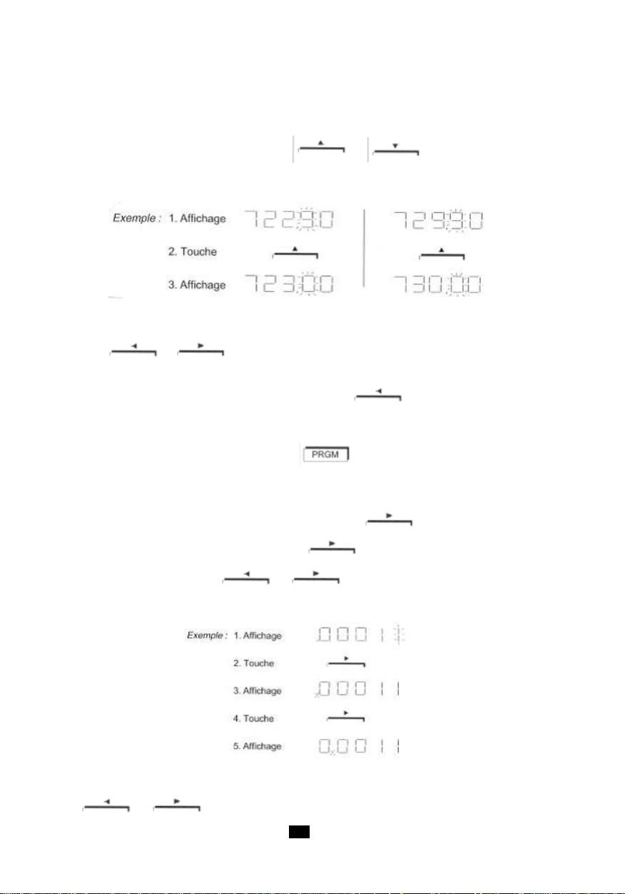
A/ Ecriture d‘un nombre sans virgule :
Lors d‘affichage de tirets, l‘appui sur une touche de déplacement horizontal entraîne le remplacement
des tirets par des zéros, par la valeur précédemment enregistrée ou par la valeur extrême possible en
compatibilité avec la fonction. L‘augmentation ou la diminution de la valeur du chiffre actif (clignotant)
s‘effectue respectivement par appui sur la touche ou . La variation vers le haut
(... 7, 8, 9, 0, 1, 2, ...) ou vers le bas (... 2, 1, 0, 9, 8, ...) d‘un chiffre incrémentera ou décrémentera
automatiquement le (ou les) chiffre(s) à gauche de celui-ci.
Si pendant les opérations d‘incrémentation ou décrémentation la capacité maximale d‘affichage est
dépassée, l‘afficheur indiquera à nouveau cinq tirets.
Les touches et permettent de déplacer respectivement vers la gauche ou vers la
droite le chiffre actif (clignotement) que l‘on cherche à programmer.
Lorsque le chiffre de gauche est actif, un appui sur la touche provoque l‘apparition des cinq
tirets ou la valeur précédemment enregistrée de la mémoire.
La validation s‘effectue par appui sur la touche ou une autre touche de programmation (ex;
SCAN).
La validation de „-----“ stoppe et annule toute programmation.
B/ Positionnement de la virgule :
Pour obtenir l‘activation de la virgule, il faut presser la touche jusqu‘à ce que le chiffre de
droite clignote. Une nouvelle pression sur la touche rend le déplacement de la virgule actif.
Toute autre pression sur la touche ou permet de positionner la virgule à l‘endroit
désiré.
Lorsque la virgule est située à l‘extrémité gauche ou droite de l‘afficheur, toute nouvelle pression sur la
touche ou provoquera l‘apparition de „-----“.
1919
Page 20
Pour obtenir le retour de la virgule sur l‘afficheur, il suffit d‘appuyer sur la touche
ou suivant que celle-ci est sortie à gauche ou à droite respectivement. Du fait des cinq
possibilités de position de la virgule, la définition de la programmation peut être plus grande que la
définition de la mesure. Dans ce cas, la comparaison des franchissements des seuils d‘alarme se fait
toujours avec la définition réelle de la mesure.
La sortie du mode programmation, ainsi que la validation se fait:
- soit par l‘appui sur la touche . On sort du mode programmation et PRGM s‘éteint.
- soit par le passage à une autre fonction de programmation en appuyant sur la touche ,
ou .
- soit par la rotation du commutateur sur une autre position, sauf „OFF“. L‘appareil repasse alors
en mode mesure. Le passage sur „OFF“ interdit la validation et entraîne la perte des valeurs en
cours. Les valeurs précédemment enregistrées restent valides. La relecture des informations
contenues en mémoire s‘effectue de la même manière que la programmation, sauf que les
touches , , ou ne doivent pas être utilisées.
Seuils d‘alarmes (C.A 1727 uniquement)
Deux seuils peuvent être fixés. La programmation de ces valeurs est obtenue par l‘appui sur la touche
en mode programmation.
Un premier appui sur la touche entraîne l‘affichage de et permet la programmation du
seuil bas.
Un second appui sur la touche valide le seuil bas (LO AL), affiche et permet la
programmation du seuil haut (HI AL).
Quand un seuil est programmé et que la fonction ALARM est activée, le symbole correspondant
apparaît sur l‘affichage en mode mesure et la valeur mesurée est constamment comparée à cette
valeur. Le dépassement du seuil entraîne l‘affichage du symbole correspondant et active le buzzer
(voir utilisation de cette fonction au paragraphe ALARME).
Lorsqu‘un ou des seuil(s) d‘alarme ont été programmé(s) et mis en service, ceux-ci apparaissent sur
le bargraphe en contraste inverse de la mesure : noir si la déviation est inférieure au seuil, blanc si la
déviation est supérieure au seuil d‘alarme, clignotant (4Hz) si la mesure est égale à la valeur du seuil.
Coéfficient K (C.A 1727 uniquement)
Le coéfficient K est un multiplicateur appliqué à la valeur brute de la mesure, permettant d‘obtenir un
affichage directement exploitable.
Exemples :
- programmation d‘un rapport de boîte. Ceci permet de visualiser directement la vitesse en sortie
d‘un réducteur par mesure de la vitesse sur l‘entrée.
- mesure de débit. Un débitmètre fournit une impulsion tous les 2m³. En Hz on a directement la
mesure du débit (K = 2) par seconde. A vec COUNT, on obtient en plus la mesure du volume qui a circulé
dans la canalisation.
La pression de la touche en mode PRGM permet la programmation de la valeur du coéfficient
K.
20
Page 21
Dès qu‘un coéfficient autre que la valeur initiale est programmé, le symbole K apparaît en fonction
mesure sur l‘afficheur. L‘affichage numérique et le bargraphe tiennent alors compte du coéfficient
multiplicateur K.
L‘extinction du symbole K ne peut être obtenu qu‘en reprogrammant la valeur d‘origine du coéfficient K
(voir le tableau ci-après).
La programmation de K est limitée aux valeurs comprises entre 99,999 et 0,010. Toute autre valeur n‘est
pas prise en compte.
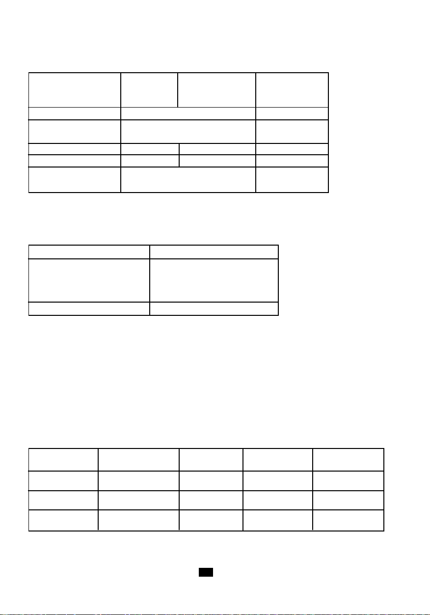
Mesure Comptage K origine
K en tr/mn K en tr 1
K en m/min K en m 0.1
K en RPM K en REV 1
K en ft/min K en ft 0.328
K en kHz, ms, % K en comptage d‘impulsions 1
La programmation d‘un coéfficient K ne change pas les limites maximales de mesure et d‘affichage
(0,1 à 10000Hz et 0 à 99999 points).
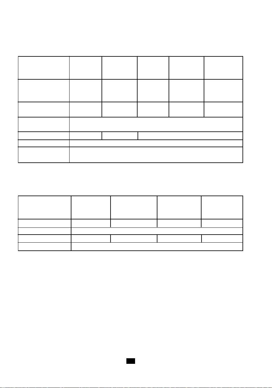
Le tableau ci-après indique les fréquences limites en fonction du coéfficient K programmé (on
suppose l‘utilisation de la prise d‘entrée externe). En dehors de ces limites, l‘affichage indiquera „OL“
en dépassement supérieur et „-----“ pour un dépassement inférieur.
Unité de mesure Coéfficient K programmé
fréq. MAX entrée 9999.9Hz 1000Hz
donnant un
affichage MAX de 99999pts 99999pts Hz
fréq. MIN entrée 0.1Hz 0.1Hz
donnant un
affichage MIN de 0.0010pts 9999pts
fréq. MAX entrée 10.000Hz 16.666Hz
tr/min ou RPM donnant un
affichage MAX de 6000.0pts 99999pts
fréq. MIN entrée 0.1Hz 0.1Hz
m/min donnant un
affichage MIN de 0.0600pts 59999pts
Unité de mesure Coéfficient K programmé
fréq. MAX entrée 10000Hz 50.8Hz
ft/min donnant un
affichage MAX de 19800pts 99999pts
fréq. MIN entrée 0.1Hz 0.1Hz
1ft = 0.3048cm donnant un
1m = 3.281ft affichage MIN de 0.1980pts 196.86pts
0.01 99.999
0.033 32.81
2121
Page 22
Intervalle d‘enregistrement (C.A 1727 uniquement)
La fonction scanning permet d‘effectuer les mesures selon une cadence prédéfinie avec enregistrement
automatique des résultats. Il est possible de stocker jusqu‘à 4000 points.
La programmation de cette fonction est obtenue en pressant la touche en mode PRGM. Le
symbole SCAN s‘affiche.
La valeur programmée fixe le nombre de secondes séparant deux enregistrements successifs. Les
limites sont de 10 secondes minimum et 99999 secondes maximum (environ 27 heures).
En mode mesure, l‘enregistrement est démarré (arrêté) par appui sur la touche , l‘affichage
des symboles PRINT et SCAN confirme l‘enregistrement en cours. (voir ENREGISTREMENT“).
Si l‘intervalle d‘enregistrement dépasse cinq minutes, l‘émétteur optique de l‘appareil est arrêté entre
chaque mesure (symbole éteint sur l‘afficheur), puis remis en marche 2 secondes avant
nouvelle mesure.
La fonction arrêt automatique du C.A 1727 est inhibée pendant toute la durée de la fonction scanning.
Le symbole est affiché.
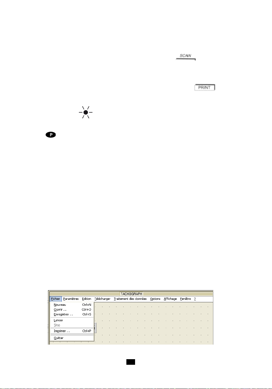
4.10 EXPLOIT A TION DES DONNÉES SUR PC (C.A 1727 UNIQUEMENT)
L'utilisation du logiciel T ACHOGRAPH permet la gestion bi-directionnelle des données contenues dans
le C.A 1727.
Il permet l'acquisition , le traitement et l'exploitation des mesures effectuées par le tachymètre C.A1727
, ainsi que le transfert des fichiers de résultats sur le disque dur d'un PC. Il permet de les traduire dans
un format compatible EXCEL, afin que l'utilisateur final puisse effectuer une exploitation numérique des
résultats à sa convenance. Il permet le transfert et l'affichage des paramètres de programmation de
l'appareil.
L'exploitation numérique des résultats ainsi que l'affichage correspondant sous forme de graphe - tels
que le calcul de la valeur moyenne ou le calcul de l'intégrale (position ) ou de la dérivée (accélération )
- sont inclus dans le logiciel TACHOGRAPH.
Les fonctions d'édition dans la fenêtre du graphe sont :
- ajout du Min + texte1 , ajout du Max + texte2 , renommer le graphe
Les fonctions d'affichage envisagées pour chaque graphe sont :
- le paramétrage de l'échelle, des couleurs ,ajout de la grille (réticule) ,de deux curseurs , d'une légende
avec affichage du delta entre les curseurs, de la fonction Zoom + et - .
Les fonctions de paramétrage pour le lancement de l'acquisition sont :
- le paramétrage de l'interface de communication RS232 , du Scan ou cadence de lecture de la mesure
, des seuils d'enregistrement , des alarmes.
Exemple de menu à l'écran du PC : Le menu Fichier
22
Page 23
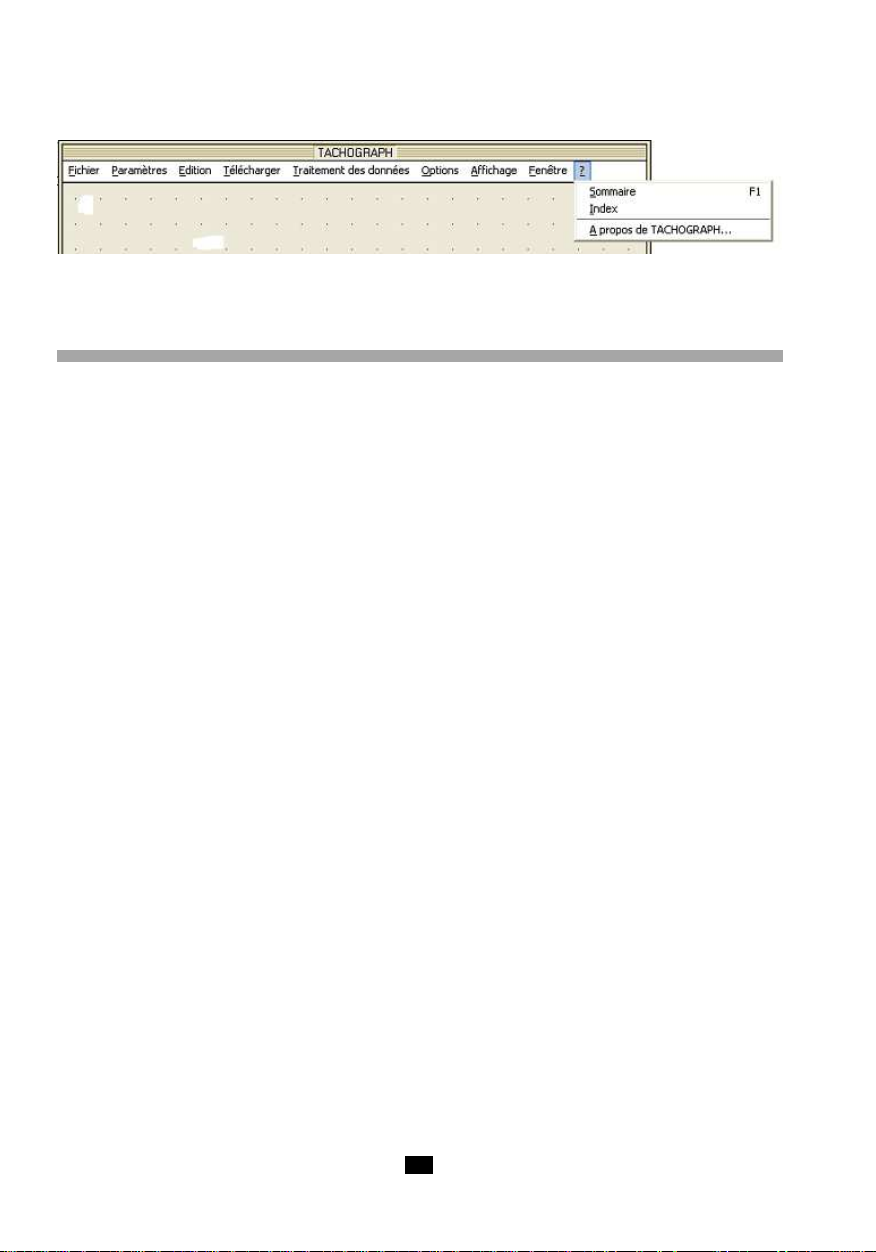
Exemple de menu à l‘écran du PC : Le menu d‘Aide?
5. ENTRETIEN
Le tachymètre ne réclame aucun entretien particulier, hormis le remplacement de la pile et le nettoyage
du boîtier.
- Réglages
L‘appareil ne possède aucun réglage interne. La précision de mesure est donnée par un quartz de
grande stabilité.
- Nettoyage du boîtier
Nettoyer avec un tissu légèrement imbibé d‘eau savonneuse puis d‘eau claire.
Une fenêtre de visée sale peut entraîner une forte dégradation des caractéristiques de visée rendant
toute mesure impossible ou instable.
- Nettoyage du kit mécanique
Nettoyer avec un tissu légèrement imbibé d‘eau savonneuse puis d‘eau claire.
L‘usage d‘alcool ou de solvant peut endommager irrémédiablement l‘adaptateur mécanique en détériorant
sa lubrification.
- Remplacement de la pile
Lorsque le symbole pile apparaît sur l‘afficheur, il est nécessaire de procéder au remplacement de
celle-ci.
- mettre le commutateur sur la position „OFF“.
- ouvrir le compartiment pile situé au dos de l‘appareil. dévisser la vis à l‘aide d‘un outil (pièce de
monnaie, ...)
- retirer la pile et remplacer par une neuve en respectant la polarité. Utiliser une pile de type
alcaline 6LF22 ou similaire.
- refermer la trappe du compartiment en bloquant légèrement la vis.
- Stockage
En cas de non utilisation prolongée, il est conseillé de retirer la pile de l‘appareil et de la stocker
séparément.
- Vérification métrologique
Comme tous les appareils de mesure ou d'essais, une vérification périodique est nécessaire.
Nous vous conseillons une vérification annuelle de cet appareil. Pour les vérifications et étalonnages,
adressez vous à nos laboratoires de métrologie accrédités COFRAC ou aux Centres Techniques
MANUMESURE.
Renseignements et coordonnées sur demande :
Tél. : 02 31 64 51 43 - Fax : 02 31 64 51 09
2323
Page 24

- Réparation
Toute intervention, autre que le remplacement de la pile et des fusibles, doit être effectuée par du
personnel qualifié et agréé.
Pour les réparations sous garantie et hors garantie, adressez votre appareil à l'un des Centres
Techniques régionaux MANUMESURE, agréés CHAUVIN ARNOUX.
Renseignements et coordonnées sur demande :
Tél. : 02 31 64 51 43 - Fax : 02 31 64 51 09
Pour les réparations hors de France métropolitaine, sous garantie et hors garantie, retournez l'appareil
à votre distributeur.
- Garantie
Notre garantie s‘excerce, sauf stipulation expresse, pendant 12 mois après la date de mise à disposition
du matériel. Extrait de nos Conditions Générales de Vente, communiquées sur demande.
La garantie ne s'applique pas suite à :
- une utilisation inappropriée de l'équipement ou à une utilisation avec un matériel incompatible ;
- des modifications apportées à l'équipement sans l'autorisation explicite du service technique
du fabricant ;
- des travaux effectués sur l'appareil par une personne non agréée par le fabricant ;
- une adaptation à une application particulière, non prévue par la définition du matériel ou non
indiquée dans la notice de fonctionnement ;
- des dommages dus à des chocs, chutes ou inondations.
6. CARACTÉRISTIQUES
6.1 CARACTÉRISTIQUES GÉNÉRALES
- Appareil : Tachymètre à capteur optique, entrée externe et entrée / sortie USB (C.A 1727
- Fonctions : Mesures de tr/min, m/min, Hz, ms et rapport cyclique.
- Enregistrement: 4000 points, cadence de 10 à 99 999s.
- Boîtier : Polycarbonate, lentille capteur en méthacrylate.
- Dimensions : 21 x 72 x 47mm
- Masse : Environ 250g.
- Etanchéité : IP51 selon norme IEC 60529 (Ed 92).
- Compatibilité éléctromagnétique :
- Sécurité : conforme à IEC 61010-1 Ed2 2001
- Alimentation: - Pile alcaline 9V 6LF22 ou équivalent.
- Environnement : - Stockage : -20 à +70°C / 95% HR max sans condensation.
uniquement).
Conforme aux exigences relatives à la CEM selon NF EN 61326-1 (Ed 97) + A1
(Ed 98) + A2 (Ed 2001).
- Autonomie moyenne : -250 mesures de 5 minutes avec capteur optique.
- 600 mesures de 5 minutes avec entrée externe.
- Fonctionnement : 0°C à +55°C / 90% HR sans condensation.
24
Page 25
6.2 CARACTÉRISTIQUES MÉTROLOGIQUES
- Conditions de références
Grandeur d‘influence Condition de référence Tolérances
Température ambiante 23°C ± 3k
Humidité relative 45% à 75% HR
Champ magnétique ext. < 40A/m à 50 ou 60Hz
Champ électrique < 1V/m à 50 ou 60Hz
Tension pile 9V ± 0,5V
Utilisation dans le domaine de référence
- capteur optique : cible mate (ne produisant aucune mesure en rotation sans adhésif réfléchissant).
- Prise externe : signal TTL normalisé 0 - 5V.
- Fonction tr/min
Calibre* tr/min 6.0000 10.000 100.00 1000.0 10000
- - - - -
9.9999 99.999 999.999 9999.9 99999
Résolution 0.0006tr/min 0.0006tr/min 0.0006tr/min 0.0006tr/min 0.0006tr/min
Précision 1.10-4 de la lecture ± 6 points
Temps de mesure 11s > t > 7s 7s > t > 1s 1s > t > 1s < 0,5s
Stabilité ± 6 points
* de 6 à 60tr/min : utilisable uniquement avec l‘entrée externe. Utilisation jusqu‘à 10000tr/min
avec l‘adaptateur mécanique.
- Fonction Hz
Pour les fréquences supérieures à 10kHz (limite supérieure du domaine d‘utilisation) l‘appareil peut
indiquer des valeurs erronées.
Calibre* Hz 0.1000 10.000 100.00 1000.0
- - - -
9.9999 99.999 999.99 9999.9
Résolution 0.0004Hz 0.004Hz 0.04Hz 0.4Hz
Précision 4.10-5 de la lecture ± 4 points
Temps de mesure 11s > t > 0,5s < 0,5s
Stabilité ± 4 points
* de 0,1 à 1kHz : utilisable uniquement avec l‘entrée extérieure.
2525
Page 26
- Fonction vitesse linéaire
Adaptateur mécanique avec roue diamètre 3,1813cm donnant K = 0,1 pour les m/min et K = 0,328
pour ft/min.
Calibre* m/min 0.60000 10.000 100.00 1000.0 10000
- - - - -
9.9999 99.999 999.99 9999.9 59999
Calibre ft/min 1.9680 10.000 100.00 1000.0 10000
- - - - -
9.9999 99.999 999.99 9999.9 59999
Résolution 0.0006m/min 0.006m/min 0.06m/min 0.6m/min 6m/min
0.0006ft/min 0.006ft/min 0.06ft/min 0.6ft/min 6ft/min
Précision 1.10-4 de la lecture ± 1 pas de résolution en m/min
hors capteur 3.10-4 de la lecture ± 1 pas de résolution en ft/min
Temps de mesure 11s>t>1,1s 1,1s>t>0,5s < 0,5s
Stabilité ± 1 pas de résolution
Précision 3.10
-3
du capteur
* de 0.6 à 6m/min et au dessus de 999.99m/min : de 1.968 à 19.680ft/min et au dessus de
3200ft/min utilisable uniquement avec l‘entrée extérieure.
- Fonction périodemètre
Calibre * ms 9999.9 999.99 99.999 9.9999
- - - -
1000.0 100.00 10.000 0.1000
Résolution 0.3ms 0.03ms 0.003ms 0.0005ms
Précision 1.10-4 de la lecture ± 5 points
Temps de mesure 11s>t>1,5s 1,5s>t>1,5s 11s>t>1,5s 11s>t>1,5s
Stabilité ± 1 pas de résolution
* de 100.0 à 9999.9ms : utilisable uniquement avec l‘entrée externe.
26
Page 27
- Fonction rapport cyclique
Calibre % *9999.9 999.99 99.999
- - -
1000.0 100.00 10.000
Résolution 0.1% 1%
Précision 0.1% de l‘échelle de 0.2Hz à 50Hz 1% de l‘échelle
0.2% de l‘échelle de 50Hz à 125Hz
Gamme de fréquence 0.2 à 125Hz 1 à 125Hz 125 à 500Hz
Temps de mesure 6s>t>0,5s 1,5s>t>0,5s < 0.5s
Stabilité ± 1 point de 0.2Hz à 50Hz ± 1 point
± 2 points de 50Hz à 125Hz
* Utilisable uniquement avec l‘entrée extérieure.
- Fonction compteur d‘évènements
Gamme de mesure de 0 à 99999 évènements
de 1Hz à 10kHz
Gamme de fréquence de 0.1Hz à 10kHz avec
de comptage l‘entrée extérieure en gamme
Précision du comptage ± 1 évènement
élargie
6.3 CARACTÉRISTIQUES DU CAPTEUR
- Conditions de mesure
- Capteur optique
Surface réfléchissante : de 10 à 90% de la surface de la cible.
Surface de la cible : en absence de l‘adhésif réfléchissant, l‘appareil ne doit pas pouvoir effectuer de
mesure.
Distance de mesure : de 1 à 50cm. La distance maximale est donnée pour un ruban adhésif réfléchissant
d‘une surface minimale de 10cm².
Angle de mesure : ±15° par rapport à la perpendiculaire de la surface réfléchissante.
- Variante dans le domaine d‘utilisation
Grandeur Limite du domaine Grandeur Variation typique Variation max
d‘influence d‘application influencée
Température -10 à + 70°C Toute grandeur ± 30ppm ± 50ppm
ambiante mesurée
Humidité 10% à 90% HR Toute grandeur < 1.10-5 non significatif
Alimentation 7 à 10V Toute grandeur non significatif
hors condensation mesurée
mesurée
2727
Page 28

- Capteur optique
Longueur d‘onde d‘émission : 890nm.
Puissance lumineuse d‘émission : dépend de la distance de visée ;
à 1cm => 0,5mW/cm²
à 50cm => 2mW/cm .
Puissance lumineuse minimale en réception : 10µW/cm².
Rapport surface réfléchissante/surface cible : > 5%.
Distance de détection : de 1 à 50cm.
Angle de visée par rapport à la perpendiculaire de la cible : 0° ±15°.
6.4 CARACTÉRISTIQUES DE L‘ADAPT ATEUR ET SES EMBOUTS
- Adaptateur mécanique
Embouts : élastomère dureté 80 shores
Pression exercée sur la pièce en mouvement : entre 2 et 40N.
Vitesse maximale : 10000tr/min.
Durée de vie : environ 1000 heures à 3000tr/min sous une pression de 20N.
- Accessoire embout conique
Cet embout permet la mesure par contact en bout d‘axe d‘un système en rotation.
C‘est un cône en élastomère (diamètre maxi 15mm) qui vient s‘ajuster sur l‘axe de sortie de l‘adaptateur,
avec verrouillage instantané.
Diamètre minimum de l‘arbre de mesure : 5mm.
- Accessoire embout cylindrique
Cet embout permet la mesure par contact en bout d‘axe d‘un système en rotation.
C‘est un cylindre en élastomère qui vient s‘ajuster sur l‘axe de sortie de l‘adaptateur, avec verrouillage
instantané.
Il permet la mesure de vitesse d‘arbres de diamètre supérieur à 5mm ou à extrémité plane.
- Accessoire embout à roue
Cet embout permet la mesure de vitesse linéaire par contact direct avec la pièce en mouvement.
C‘est une roue en élastomère, non déformable qui vient s‘ajuster sur l‘axe de sortie de l‘adaptateur,
avec verrouillage instantané.
Diamètre de la roue : 30,183mm.
Développement de la roue : 10cm ± 0,1mm
28
Page 29

7. POUR COMMANDER
TACHYMÈTRE C.A 1725........................................................................P01 174810
Livré dans sa malette avec 1 connecteur FRB F, 1 pile 9V, 1 jeu de 15 films rétro réfléchissants
(longueur de 0,1m), 1 notice de fonctionnement sur CD ROM et un Guide de démarrage rapide sur
papier.
ACCESSOIRES du C.A 1725
- Kit accessoires mécaniques ........................................................................................... P01174902
Composé de 1 adaptateur mécanique, 1 roue calibrée, 1 embout conique, 1 embout cylindrique.
RECHANGES du C.A 1725
- Embouts (jeu de 3) ...........................................................................................................P01174903
composé de 1 roue calibrée, 1 embout conique, 1 embout cylindrique
- Pile 9V .............................................................................................................................. P01100732
- Film rétro réfléchissant (15 bandes de 0,1m) .................................................................P01100797
- Prise FRB F.......................................................................................................................P01101785
T ACHYMÈTRE C.A 1727........................................................................P01174830
Livré dans sa malette avec 1 connecteur FRB F, 1 pile 9V, 1 jeu de 15 films rétro réfléchissants
(longueur de 0,1m), 1 notice de fonctionnement sur CD ROM, 1 logiciel T ACHOGRAPH sur CD ROM, 1
cordon USB C.A 1727 <--> PC et un Guide de démarrage rapide sur papier.
ACCESSOIRES du C.A 1727
- Kit accessoires mécaniques ........................................................................................... P01174902
Composé de 1 adaptateur mécanique, 1 roue calibrée, 1 embout conique, 1 embout cylindrique.
- Logiciel T ACHOGRAPH sur CD ROM ...............................................................................P01174835
- Cordon USB-A <--> USB-B ..............................................................................................P01295293
RECHANGES du C.A 1727
- Embouts (jeu de 3) ...........................................................................................................P01174903
composé de 1 roue calibrée, 1 embout conique, 1 embout cylindrique
- Pile 9V .............................................................................................................................. P01100732
- Film rétro réfléchissant (15 bandes de 0,1m) .................................................................P01100797
- Prise FRB F.......................................................................................................................P01101785
2929
Page 30
Meanings of the symbols used on the device
WARNING, DANGER!
Refer to the user manual whenever you see this symbol.
This marking certifies compliance with the European "Low Voltage" and "Electromagnetic
Compatibility" directives (73/23/CEE and 89/336/CEE).
In the European Union, this product is subject to sorting for the recycling of electrical and
electronic equipment in accordance with WEEE directive 2002/96/EC.
You have just purchased a C.A 1725 / C.A 1727 Tachomater, thank you for your confidence.
For best results from your instrument :
• Read these operating instructions carefully.
• Observe the precautions for use.
PRECAUTIONS FOR USE
For measurements without mechanical contact :
Before using the tachometer, check that the front sighting window is perfectly clean.
The minimum detection distance is 1cm; but take care to avoid the immediate vicinity of any moving part,
which might be dangerous for the operator and for the device.
For measurements with mechanical contact :
Keep your hands as far as possible from the moving part.
Do not press too hard, since this might brake the moving part and result in an erroneous measurement.
For measurements on shaft ends, position the device as close as possible to the axis of the shaft.
For measurements using an external input :
The use of the external connector requires observance of the rules concerning the interconnection of
counting devices and industrial interference.
Use shielded wires connected to an earth that is not exposed to the switching transients of power
systems.
The received interference must not exceed the amplitude of the hysteresis fixed in the device (250mV).
The external input is limited to a common mode of not more than 50 volts.
ATTENTION :
The external sensor connector uses the same earth as the USB digital output
30
Page 31

CONTENTS
1. INTRODUCTION ...................................................................... 32
2. DESCRIPTION......................................................................... 32
2.1 TACHOMETER........................................................................................................................ 32
2.2 DISPLAY UNIT........................................................................................................................ 35
3. USE .......................................................................................... 37
3.1 CONTACT -FREE MEASUREMENTS ........................................................................................ 37
3.2 MEASUREMENTS WITH CONTACT........................................................................................ 37
3.3 MEASUREMENTS WITH EXTERNAL INPUT ........................................................................... 38
4. OPERA TION............................................................................. 40
4.1 MEASUREMENT UNITS .......................................................................................................... 40
4.2 MIN/MAX RECORDING ........................................................................................................... 41
4.3 HOLD OF THE DIGIT AL V ALUE ON THE DISPLA Y ................................................................ 42
4.4 SMOOTHING OF THE MEASUREMENT .................................................................................. 43
4.5 MANUAL CHOICE OF RANGE ............................................................................................... 43
4.6 COUNTING (C.A1727 only) ................................................................................................... 44
4.7 RECORDING OF MEASUREMENTS (C.A 1727 only) ............................................................. 44
4.8 ALARMS (C.A 1727 only) ..................................................................................................... 45
4.9 PROGRAMMING (C.A 1727 only) .......................................................................................... 46
4.10 PROCESSING OF THE DATA ON A PC (C.A 1727 only) ........................................................ 50
5. MAINTENANCE ....................................................................... 51
6. CHARACTERISTICS ............................................................... 52
6.1 GENERAL CHARACTERISTICS ............................................................................................. 52
6.2 METROLOGICAL CHARACTERISTICS................................................................................... 53
6.3 CHARACTERISTICS OF THE SENSOR .................................................................................. 55
6.4 CHARACTERISTICS OF THE ADAPTER AND ITS END FITTINGS .......................................... 56
7. TO ORDER............................................................................... 57
3131
Page 32
1. INTRODUCTION
C.A 1725 and C.A 1727 tachometers, specially designed for industrial applications, measure the speed
of rotation of any moving part at a distance or by contact.
CHAUVIN ARNOUX tachometers provide many possibilities in addition to the usual functions:
- Direct reading of the measurement
- Measurement of period, of frequency, of duty cycle, of linear speed
- Measurement by external sensor
- Special functions: smooth, range, hold, etc.
- Dual display: 100,000-point digital and bargraph.
- The C.A 1727 can be parameterized and has a USB link; associated with its specific software, it
provides an extensive range of measurement, acquisition, processing, and data analysis possibilities.
2. DESCRIPTION
2.1 T ACHOMETER
1 Optical sensor
2 key
- Tore last digital value displayed.
- Disable automatic stop.
key on the C.A 1727 only :
- For programming : shift the selection of the active digit or of the decimal point to the right.
3 key
- Smooth the measurements.
key on the C.A 1727 only :
- For programming : increment the active digit.
4 key on the C.A 1727 only :
- Activate the audible and visual alarms.
- Program the alarm thresholds.
5 key on the C.A 1727 only :
- Command recording of the measurements in memory.
key on the C.A 1727 only :
- Program the rate at which the measurements are recorded in memory.
6 USB output connector, on the C.A 1727 only.
7 Connector for external input.
8 Rotary switch.
32
Page 33
9 key on the C.A 1727 only :
- Programming.
- Initialize the program memory .
10 key on the C.A 1727 only :
- Event counter.
key on the C.A 1727 only :
- Program the scale factor : coefficient K.
11 key
- Manual or automatic change of range.
- Extend the measurement range at low frequency.
key on the C.A 1727 only :
- For programming : decrement the digit.
12 key
- Record minima and maxima.
- Disable the buzzer.
key on the C.A 1727 only :
- For programming : shift the selection of the active digit or of the decimal point to the left.
3333
Page 34

34
Page 35

2.2 DISPLA Y UNIT
1 Programming mode, on the C.A 1727 only.
2 Low threshold crossed, on the C.A 1727 only.
3 Full-scale coefficient K, on the C.A 1727 only.
4 Low threshold function, on the C.A 1727 only.
5 Memory write function, on the C.A 1727 only.
6 High threshold function, on the C.A 1727 only.
7 High threshold crossed, on the C.A 1727 only.
8 Rate of recording of measurements function, on the C.A 1727 only.
9 Transmission or reception in progress, on the C.A 1727 only.
10 Flashing indicator of operation of the infrared sensor.
11 Full-scale value of the bargraph (from 2 to 200 x 1000).
12 Analogue display by bargraph.
13 Arrowhead(s) indicating overshoot of end of scale.
14 Speed of rotation - Revolutions per minute
15 Revolutions: count of number of revolutions, on the C.A 1727 only.
16 metres per minute: linear speed.
17 Hertz: frequency.
18 Digital display, 5 digits.
19 Measurements in smoothed values.
20 Frozen display of the last measurement.
21 Recording paused.
22 Device in permanent operation.
23 Battery charge indicator.
24 MIN/MAX recording.
25 Buzzer active indicator.
26 Reading of MAX memory.
27 Measurement range extended to 0.1 Hz.
28 Reading of MIN memory .
29 Disable automatic change of range.
30 Counting function, on the C.A 1727 only.
31 Millisecond: period.
32 Duty cycle.
33 · ft/min: feet per minute - linear speed (in English).
· tr/min: revolutions per minute - speed of rotation.
34 Graduated fixed scale.
35 Measurement by external connector.
36 Optical transmitter in action.
3535
Page 36

36
Page 37

3. USE
3.1 CONTACT -FREE MEASUREMENTS
The contact-free measurement is made by the optical sensor built into the device. This sensor, placed
in the front of the device, comprises a frequency-modulated infrared transmitter.
Before making any measurement, it is necessary to prepare the revolving target of which the speed is
to be determined.
Check that the surface sighted is free of spurious reflections that might be counted in addition to the
pulses from the reflecting adhesive. Proceed as follows: before applying the adhesive used to make
the measurement, turn the target and check that when it is sighted the reading remains at ---. If not, it
will be necessary to cover the entire surface of the target with a mat black medium.
When the target is correct, apply a reflecting adhesive tape on it, along the longest available radius. On
small targets, the area covered by the adhesive tape must be less than 50% of the total area of the
rotating part.
Start the target turning, aim the front of the device at it, and check that the measurement OK symbol
flashes regularly.
The distance between the sensor and the target must be between 1 and 50cm.
The measurement angle of 30° (15° on either side of the perpendicular to the target) is convenient for
aiming purposes.
During measurements of low speeds, very small movements of the device may make the measurement
unstable: if this happens, we recommend placing the device on a stable support. There is a nut on the
underside of the device for attachment to a tripod or similar support.
3.2 MEASUREMENTS WITH CONTACT
The mechanical adapter and its 3 end fittings allow measurement by contact on a shaft end or on a
surface in linear motion.
It is placed in front of the sighting window of the optical sensor and accepts one of the following 3 end
fittings:
- An elastomer cone with a tip that can be used for shaft end measurements
(minimum diameter: 5mm).
- An elastomer cylinder that can be used for measurements on shafts with flat ends or shafts
smaller than 5mm.
- An elastomer wheel for linear speed measurements (1 revolution of the wheel = 0.1m).
The end fitting must be pressed against the moving part just hard enough to drive it without slippage.
The adapter is attached to the front of the tachometer housing, in front of the sighting window. It
automatically locks in position when pushed home.
- Fitting
To attach the adapter, align the three lugs on the inside of the adapter with the three recesses of the
sighting window of the housing and turn anticlockwise.
- Removal
To remove it, pull the adapter outward until the locking tabs are clear, then turn clockwise.
3737
Page 38

3.3 MEASUREMENTS WITH EXTERNAL INPUT
The device has a 4-contact connector that can be used to connect an external source of which you
wish to measure the speed, the frequency, the period, the duty cycle, etc.
In order to inform the tachometer that the measurement is available on the external input, it is necessary
to short-circuit contacts 1 and 4.
Operation using the external input is indicated on the display unit by the extinction of the transmission
symbol and the display of EXT.
Wiring
Connector of the tachometer 2- measurement input (± 20VC max.)
seen from contact side 3- see below
Connecting 1 to contact 3 makes it possible to adapt the triggering threshold to the nature of the signals.
Contacts 1 and 3 not connected
For operation with 0 - 5V TTL signals.
The triggering threshold is +1.1V (at 1kHz).
To avoid the problems due to noise often present in an industrial environment, the threshold has a
hysteresis of 250mV.
Contacts 1 and 3 connected
For operation with signals balanced with respect to earth.
This function allows direct measurement using a variable-reluctance magnetic sensor or the output of
an alternator.
The triggering threshold is 300mV (at 1kHz), with a hysteresis of 250mV . The residual noise superimposed
on the signal to be measured must be less than 250mV so as not to interfere with the measurement
when the threshold is crossed.
ATTENTION :
The maximum voltage to input no. 2 must not exceed ± 20Vp. The earth of the external input
connected is electrically connected to the earth of the USB digital output.
1- earth
4- to be short-circuited with contact no.1
The external input must be used for the measurement of slow signals, from 0.1Hz. The table below
sums up the characteristics of this input.
38
Page 39
Measurement frequency range from 1Hz to 10kHz
from 0.1Hz to 10kHz in expanded range
Functions available same as optical sensor
Accuracy same as optical sensor
Input impedance ≥ 75kΩ
Balanced signals mode 300mV ± 90mV at 1kHz
Thresholds 600mV ± 160mV at 10kHz
Hysteresis 250mV ± 80mV
TTL signals mode 1.1V ± 150mV to 1kHz
Thresholds 2.2V ± 300mV to 10kHz
Hysteresis 250mV ± 80mV
Maximum voltage ± 20V peak
Acceptable overload (1second) 250Vrms
Example of DUTY CYCLE Measurement on EXTERNAL INPUT
When the external input is used, the FRB connector provided with the device must be connected to the
source of the signal to be measured, then to the connector marked EXT.
Consider a signal like the one shown in the figure below:
Here, the frequency of the signals is given by the formula :
1
f =
T
T = 5 x 1ms = 5ms
1
so f = = 200Hz
5.10
-3
3939
Page 40
The duty cycle is given by :
t
Duty =
or, in %. Duty % = x 100
Here, we have :
1
t1 + t
2
t
1
t1 + t
2
3
Duty % = x 100 = 60%
3 + 2
To make this measurement with the C.A 1725 or C.A 1727 tachometer, you must:
1) Check the amplitude of the input signal to the device. This serves to determine what threshold
must be set. Here, the amplitude is greater than +1.1 V, so contacts 1 and 3 of the FRB
connector must not be interconnected.
2) Switch the tachometer on by setting the rotary switch to "%".
3) The display unit indicates directly the result mentioned above.
If there is no reading on the display unit, check that the amplitude of the signal to be measured is above
the triggering threshold.
4. OPERATION
4.1 MEASUREMENT UNITS
The table below indicates the display capacity for each function.
Function Display
tr/mn or RPM 60.000 to 99999
m/mn (K = 0.1) 6.0000 to 99999
ft/mn (K = 0.328) 19.680 to 99999
Hz 1.0000 to 9999.9
Period (ms) 0.1000 to 999.99
Duty cycle % 0.1 to 99.9
Counter 0 to 99999
In a measurement extended to 0.1Hz using the Ext input, the minimum values are divided by 10.
On/Off function:
If this function is not overridden when the device is switched on (see below), the device is switched
off automatically if one of the following has not occurred during the last 5 minutes:
- Press of a key,
- Or change of setting of the rotary switch,
- Or interrogation of the digital output.
Before switching off automatically, the tachometer emits an audible beep.
40
Page 41
Special functions :
The following special functions are obtained when a key is kept pressed when the device is switched
on:
KEY FUNCTION
No key pressed Switched on for 5 minutes
Switched on for an indefinite duration
appears on the display unit
Switched on without buzzer
The symbol does therefore not appear
Initialization of all values contained in the program memory.
The display unit indicates „Init“
Measurement down to 0.1Hz
SLOW lights on the display unit.
4.2 MIN / MAX RECORDING
The recording function can be used to store the minimum and maximum values of the measurements.
Pressing the key switches the device into recording mode. The RECORD and symbols
are displayed. The automatic switching off function is disabled.
MIN value
Initially, the value store is OL (OVER LOAD). When the key is pressed, the value displayed
is stored in the MIN register.
Whenever a value below the value storedd in the register is measured, it is transferred to the MIN
register and 1kHz audible beep is emitted.
MAX value
The value stored at the start is zero. A measured value greater than the value stored in the register
leads to an update.
Each time the content of the MAX memory is modified, a 2 kHz audible beep is emitted.
Reading of the MIN/MAX memories
The values contained in the MIN and MAX registers can be displayed by successive presses
on .
The circular display indicates in turn the MAX, the MIN and the current measurement value.
Recording continues during the reading; the bargraph indicates the instantaneous measurement.
NB: if the "SMOOTH" function is activated, the MAX and MIN are determined from the smoothed values.
Stopping the MIN/MAX recording function
The recording function is stopped either by a long press on the key or by turning the switch.
Remark : The MIN/MAX functions is not available in counting mode.
4141
Page 42

4.3 HOLD OF THE DIGIT AL V ALUE ON THE DISPLA Y
HOLD memory
MAX memory
HOLD
RECORD PAUSE MAX RECORD PAUSE
Instantaneous
measurement
MIN memory
RECORD PAUSE
MIN RECORD
PAUSE
MIN MAX
MIN MAX
MIN MAX
MIN MAX
By a brief press on the HOLD key (when not in programming mode).
Pressing HOLD freezes the digital display on the last measurement displayed; the bargraph continues
to indicate the instantaneous measurement value. The display indicates HOLD. Pressing the HOLD key
again restores the display of the instantaneous measurements, and HOLD disappears from the display
unit.
in the „MIN/MAX“ recording mode
When the key is pressed while RECORD is displayed :
- The HOLD and P AUSE symbols are displayed.
- Recording stops and the values contained in the MIN and MAX memories are the last values
before .
- The digital display unit indicates the last measurement value, or else the MIN or MAX value if the
device was reading them back.
- The bargraph continues to indicate the current measurement.
Pressing the key again causes the recording of the MIN and of the MAX to resume :
- The HOLD and PAUSE symbols remain displayed.
- The display unit indicates the measurement in progress or the content of the MIN/MAX memory
being read back.
- The device is once again in MIN/MAX mode, but the memories have not been reset and they
contain the MIN and MAX values present before the .
When the HOLD and RECORD - PAUSE symbols are displayed, it is always possible to display, in a
circular manner, the values in the memories and the instantaneous measurement value, by brief
presses on the
.
The bargraph always indicates the current measurement value.
Whatever display is in progress :
- A brief press on the key restores recording without resetting the memories.
- A long press on the key stops recording.
42
Page 43
Application :
When the tachometer is used in a place where it is difficult or impossible to read the display unit, the
HOLD function can be used in conjunction with MIN/MAX recording to store the minimum and maximum
values reached.
4.4 SMOOTHING OF THE MEASUREMENT
Pressing the key starts the smoothing of the measurement (SMOOTH displayed). The digital
value indicated is then the sliding average of the last 10 measurements (approximately 5 seconds).
The bargraph always indicates the instantaneous measurement.
In MIN/MAX recording, if the SMOOTH symbol is displayed, the values recorded are the smoothed
values.
Activating or deactivating the SMOOTH mode during MIN/MAX recording cancels the MIN and MAX
values already stored.
Remark: The SMOOTH function has no effect on the counting function.
4.5 MANUAL CHOICE OF RANGE
When the device is switched on, or during a change of function, the device automatically selects the
most appropriate measurement range. Each function has 4 or 5 ranges, except for the duty cycle
function (2 ranges).
In automatic operation, the digital display unit has a display capacity of 20,000 points and the possible
full-scale values of the bargraph are 2, 20, 200, 2000, 20,000, and 200,000.
In the automatic mode, the digital display unit switches to a higher range when
20,000 points is reached.
A first brief press (<2 s) on the key freezes the current measurement range. RANGE
appears on the display unit. The digital indicator then has a display capacity of 100,000 points.
Each new press on the key switches both displays (bargraph and digital) to the next
higher range. From the highest range (20,000) the key switches the device to the 2 range.
To exit from the manual range change mode, press the key for more than 2 seconds.
Remark:
If the measurement value exceeds the display capacity, the display unit indicates OL and the range
overshoot arrow appears to the right of the bargraph.
ATTENTION :
The functions described in the paragraphs that follow are available only on the C.A 1727.
4343
Page 44

4.6 COUNTING (C.A 1727 ONL Y)
Press the COUNT key to switch the device into the event counting mode. COUNT appears on the display
unit and the measurement units are changed (see table below).
Measurements mode COUNT mode
tr/min rev (revolution)
m/min m (metre)
RPM REV (revolution)
ft/min ft (foot)
Hz /
ms /
Duty % /
The Hz, ms, and % symbols disappear. There is no longer a measurement unit displayed; the device
simply counts the number of pulses received.
A press on the key stops the counting. A second press causes the counting that was
paused to resume.
When 99,999 events are reached, the display changes to OL.
To exit from the counting mode, simply press the key again. The counter is reset by 2
successive presses on the key.
Remarks:
- As standard, the device counts metres or feet, with a measurement resolution equal to the circumference
of the end fitting used, 0.1m or 0.328ft. This resolution can be changed by changing the value of K.
- In the counting mode, the recording, change of range, and smoothing functions are not available.
4.7 RECORDING OF MEASUREMENTS (C.A 1727 ONL Y)
The key can be used to record the value displayed.
- with HOLD :
The record will be the last value displayed, preceded by HOLD.
- with MIN/MAX recording :
When the device is in recording mode (RECORD, MIN or MAX on the screen), the PRINT command
records the MIN, the MAX and the current measurement.
- with record MIN MAX + HOLD :
In this mode (RECORD - PAUSE and HOLD symbols displayed), the PRINT command records the
following four parameters:
- The HOLD value
- The value contained in the MIN register
- The value contained in the MAX register
- The current measurement value.
44
Page 45

- with SMOOTH
Digital measurement > low threshold
(LO AL)
No action
Digital measurement < high
threshold (HI AL)
No action
Digital measurement < low threshold
Continuous buzzer at 1
kHz
Display of
Digital measurement > high
threshold
Continuous buzzer at 4
kHz
Display of
If the value of LO AL is greater than the value of HI AL, this
operation is reversed. The buzzer is triggered (at 2 kHz) in the
central zone between the HI AL and LO AL values.
The value recorded is then the smoothed value, when this function is displayed (SMOOTH).
For the entire duration of recording of the information, the PRINT and COM symbols are displayed.
When the Scanning function is programmed (see "Recording Interval"), pressing the key
starts the measurement recording cycle according to the interval programmed. The SCAN symbol is
displayed and remains displayed for the entire duration of the scanning operation. PRINT and COM are
displayed each time data are transmitted to the memory.
A second press on the key interrupts the scanning; the last data are transmitted and the
SCAN, PRINT , and COM symbols go of f.
Further presses on the key alternately start and stop the function.
4.8 ALARMS (C.A 1727 ONL Y)
When thresholds have been programmed, a brief press on the key activates detection of the
croosing of these thresholds by the measurement.
The or symbol is displayed, or both, according to the type of threshold programmed.
The operation of the device is summed up in the table below.
If no threshold value has been programmed, an audible beep is emitted when the key is
pressed and the command is not accepted.
To stop the Alarm function, press the key again.
4545
Page 46

4.9 PROGRAMMING (C.A 1727 ONL Y)
The device lets you program four values to define:
- A low alarm threshold (LO AL).
- A high alarm threshold (HI AL).
- A multiplier coefficient (K).
- A recording interval (SCAN).
A press on the key switches the C.A 1727 into programming mode; PRGM is displayed.
In the programming mode, the C.A 1727 no longer makes measurements; the bargraph is off, the optical
transmitter is off.
The functions of the keys become those indicated in yellow above each key.
Functions of the keys in Functions of the keys in
measurement mode pogramming mode
Shift left
Shift right
Increment active digit
Decrement active digit
Program scanning
Program threshold
Program coefficient K
Procedure
The explanations below describe the procedure to follow to program the various memories of the
C.A 1727. These stages are common to all functions: scanning, thresholds, and coefficient K.
The "Alarm thresholds" to "Recording interval" paragraphs describe the features specific to each function.
Before switching the C.A 1727 to programming mode, you must choose, on the rotary switch, the
function of which you wish to program the values.
Pressing the key displays the PRGM symbol, switches off the bargraph, and displays "-----".
The second stage is choosing the function to be programmed, by pressing
the: ; or key.
The digital display unit then indicates the value contained in the memory , or "-----" if nothing has yet been
programmed (when programming for the first time, or if the last programming disabled this function). At
the same time, the left-hand digit (or dash) flashes.
Programming is on 100,000 points (0 to 99,999), and there are 5 possible positions of the decimal point
for the alarm thresholds (the decimal point is fixed for K and the SCAN interval has no decimal point).
A value is entered in memory as follows:
A/ writing of all digits of the desired value, without taking account of the decimal point.
B/ positioning of the decimal point.
46
Page 47

A/ Writing of a number without a decimal point:
When the dashes are displayed, pressing a horizontal shift key replaces the dashes by zeros, by the
value previously recorded, or by the extreme value possible compatible with the function. The value of
the active digit (flashing) is incremented or decremented by pressing the
key, respectively. Increasing a digit from 9 to 0 automatically increments the digit (or digits) to the left of
it, while decreasing a digit from 0 to 9 automatically decrements the digit (or digits) to the left of it.
Example :
1. Display
2. Key
3. Display
If during the incrementation or decrementation operations the maximum display capacity is exceeded,
the display unit reverts to displaying five dashes.
The and keys are used to shift the active digit (flashing), the one to be programmed,
to the left or to the right, respectively.
When the left-hand digit is active, pressing the key causes the appearance of the five
dashes or of the value previously recorded in memory.
Validation is effected by pressing the key or another programming key (e.g. SCAN).
Validating "-----" stops and cancels all programming.
B/ Positioning of the decimal point:
To activate the decimal point, you must press the
Pressing the key again activates the shifting of the decimal point. The and/
key until the right-hand digit flashes.
or .
or key can then be pressed to set the dcimal point to desired position.
Example :
1. Display
2. Key
3. Display
4. Key
5. Display
When the decimal point is located on the left or right side of the display unit, pressing
the or key, respectively, causes the appearance of „-----“.
4747
Page 48
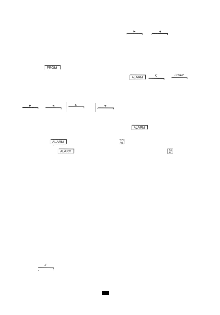
To return the decimal point to the display unit, simply press the or key, depending
on whether the decimal point exited on the left or right, respectively. Because there are five possible
positions of the decimal point, the resolution of the programming may be finer than the resolution of the
measurement. When this is the case, the crossing of the alarm thresholds is still determined according
to the true measurement resolution.
To exit from the programming mode, and to validate:
Either press the . You leave the programming mode and PRGM goes off.
- Or switch to another programming function by pressing , or key.
- Or turn the switch to any other position except "OFF". The device then returns to measurement
mode (switching to "OFF" disables validation and entails the loss of the current values; the
values previously recorded remain valid).
The information contained in memory is read back in the same way as it is programmed, except that
the , , and keys must not be used.
Alarm thresholds (C.A 1727 only)
Two thresholds can be set. To program these values, press the key when in programming
mode.
A first press on the key results in the display of and lets you program the low threshold.
A second press on the key validates the low threshold (LO AL), displays and lets you
prigram the high threshold (HI AL).
When a threshold is programmed and the ALARM function is activated, the corresponding symbol
appears on the display in measurement mode and the measured value is compared to this value at all
times. An overshoot of the threshold results in the display of the corresponding symbol and activates
the buzzer (see the use of this function in the "ALARM" section).
When one or both alarm thresholds have been programmed and activated, it or they appear on the
bargraph in reverse video (with respect to the measurement): black if the deviation is below the
threshold, white if the deviation is above the alarm threshold, flashing (4 Hz) if the measurement is
equal to the threshold value.
Coefficient K (C.A 1727 only)
Coefficient K is a multiplier applied to the raw measurement value in order to obtain a display that can
be used as is.
Examples:
- Programming of a gearbox ratio. This makes it possible to display, directly, the output speed of
a reduction gear while measuring the input speed.
- Flow measurements. A flow meter delivers one pulse every 2 m3. Setting a coefficient of K =
2 makes the reading in Hz equal to the flow rate in m3 per second. The COUNT function delivers,
in addition, the total volume that has flowed through the pipe.
Pressing the key in the PRGM mode lets you program the value of coefficient K.
When a coefficient other than the initial value has been programmed, the symbol K appears on the
display unit in the measurement mode. The digital display and the bargraph then both apply multiplier
coefficient K.
48
Page 49

The K symbol can be made to disappear only by reprogramming the original value of coefficient K (see
the table below).
The programming of K is limited to values between 99.999 and 0.010. No other values are accepted.
Measurement Counting Original K
K in tr/mn K in revolutions 1
K in m/min K in m 0.1
K in RPM K in REV 1
K in ft/min K in ft 0.328
K in kHz, ms, % K in pulse count 1
Programming a coefficient K does not change the maximum measurement and display limits (0.1 to
10,000Hz and 0 to 99,999 points).
The table below indicates the frequency limits as a function of the programmed value of coefficient
K (it is assumed that the external input connector is used). Beyond these limits, the display indicates
"OL" for an overshoot and "-----" for an undershoot.
Measurement unit Programmed coefficient K
MAX input freq., 9999.9Hz 1000Hz
giving a MAX
display of 99999pts 99999pts
Hz
MIN input freq., 0.1Hz 0.1Hz
giving a MIN
display of 0.0010pts 9999pts
MAX input freq., 10.000Hz 16.666Hz
tr/min or RPM giving a MAX
display of 6000.0pts 99999pts
MIN input freq., 0.1Hz 0.1Hz
m/min giving a MIN
display of 0.0600pts 59999pts
Measurement unit Programmed coefficient K
MAX input freq., 10000Hz 50.8Hz
ft/min giving a MAX
display of 19800pts 99999pts
MIN input freq., 0.1Hz 0.1Hz
1ft = 0.3048cm giving a MIN
1m = 3.281ft display of 0.1980pts 196.86pts
0.01 99.999
0.033 32.81
4949
Page 50
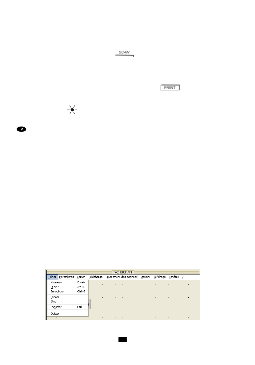
Recording interval (C.A 1727 only)
The scanning function is used to make measurements at a preset rhythm and automatically record the
results. It is possible to store up to 4000 points.
This function is programmed by pressing the key in PRGM mode. The SCAN symbol is
displayed.
The value programmed is the number of seconds between two successive records. The limits are 10
seconds minimum and 99,999 seconds maximum (approximately 27 hours).
In measurement mode, recording is started (stopped) by pressing the key; the display of the
PRINT and SCAN symbols confirms that recording is in progress (see "RECORDING").
If the recording interval exceeds five minutes, the optical transmitter of the device is switched off
between measurement ( symbol off on the display unit), then switched back on 2 seconds before
the next measurement.
The automatic stop function of the C.A 1727 is disabled for the duration of the scanning function. The
symbol is displayed.
4.10 PROCESSING OF THE DA T A ON A PC (C.A 1727 ONL Y)
TACHOGRAPH software can be used for two-way management of the data contained in the C.A 1727.
It allows the acquisition, processing, and analysis of the measurements made by the C.A 1727
tachometer, and the transfer of result s files to the hard disc of a PC. It can be used to translate them into
a format compatible with EXCEL, to allow the end user to perform any desired digital processing of the
results. It allows the transfer and display of the programming parameters of the device.
Digital processing of the results, such as calculation of the mean value, of the integral (position), or of
the derivative (acceleration), and the corresponding display in graph form are included in the
TACHOGRAPH software.
The editing functions available in the graph window are:
- Addition of Min + text1, addition of Max + text2, rename the graph.
The display functions available for each graph are:
- Parameterizing of the scale, of the colours, addition of the grid (reticule), of two cursors, of a key
with display of the delta between the cursors, of the Zoom + and - function.
The parameterizing functions for the start of acquisition are:
- Parameterizing of the RS232 communication interface, of the Scan or rate of reading of the
measurement, of the recording thresholds, of the alarms.
Example of menu on the screen of the PC: The File menu
50
Page 51

Example of menu on the screen of the PC : The help menu (?)
5. MAINTENANCE
The tachometer requires no special maintenance other than changing the battery and cleaning the
housing.
- Adjustments
The device has no internal adjustments. Measurement accuracy is ensured by a highly stable crystal
oscillator.
- Cleaning the housing
Clean with a cloth moistened with soapy water, then plain water.
A dirty sighting window can severely impair the sighting characteristics, making any measurement
impossible or unstable.
- Cleaning the mechanical kit
Clean with a cloth moistened with soapy water, then plain water.
The use of alcohol or of another solvent might irreversibly damage the mechanical adapter by degrading
its lubrication.
- Replacement of the battery
When the battery symbol appears on the display unit, the battery must be replaced.
Set the switch to "OFF".
- Open the battery compartment, located on the back of the device. Unscrew the screw using a tool
(coin, etc.)
- Remove the battery and insert a new one in its place, taking care with the polarity. Use a 6LF22 or
similar alkaline battery.
- Close the cover of the compartment and tighten the screw moderately.
- Storage
For extended periods of non-use, we recommend removing the battery from the device and storing it
separately.
- Metrological check
As with all measuring and testing devices, a periodic check is necessary.
We recommend an annual check of this device. For checks and calibrations, contact one of our
COFRAC-accredited metrology laboratories or a MANUMESURE Technical Centre.
Information and coordinates on request:
Tel.: +33 (0)2.31.64.51.43 Fax: +33 (0)2.31.64.51.09
5151
Page 52

- Repair
Any work other than replacement of the battery and fuses must be done by qualified, accredited
personnel.
For repairs, whether or not under warranty, send your device to one of the CHAUVIN ARNOUXapproved MANUMESURE regional T echnical Centres.
Information and coordinates on request:
Tel.: +33 (0)2.31.64.51.43 Fax: +33 (0)2.31.64.51.09
For repairs outside metropolitan France, whether or not under warranty, send the device to your
distributor.
- Warranty
Our warranty is valid, except as otherwise expressly stipulated, for twelve months, counting from the
date on which the equipment is made available (extract from our General Terms of Sale, communicated
on request).
The warranty does not apply following:
- inappropriate use of the equipment or use with incompatible equipment;
- modifications made to the equipment without the explicit permission of the manufacturer's
technical staff;
- work done on the device by a person not approved by the manufacturer;
- adaptation to a particular application not anticipated in the definition of the equipment or not
indicated in the operating instructions;
- damage by shocks, falls, or floods.
6. CHARACTERISTICS
6.1 GENERAL CHARACTERISTICS
- Device: Tachometer with optical sensor, external input, and USB input / output (C.A 1727 only).
- Functions: Measurements of rpm, m/min, Hz, ms, and duty cycle.
- Recording : 4000 points, recording interval from 10 to 99 999s.
- Housing: Polycarbonate, sensor lens made of methacrylate.
- Dimensions: 21 x 72 x 47mm
- Mass: Approximately 250g.
- Tightness: IP51 as per standard IEC 60529 (Ed 92).
- Electromagnetic compatibility: In conformity with EMC requirements as per NF EN 61326-1 (Ed
- Safety: in conformity with IEC 61010-1 Ed.2 2001
- Power supply:
- Environment:
97) + A1 (Ed 98) + A2 (Ed 2001)
- 6LF22 or equivalent 9V alkaline battery.
- Mean battery life: - 250 5-minute measurements with optical sensor.
- 600 5-minute measurements with external input.
- Storage: -20 to +70°C / 95% RH max without condensation.
- operation: 0°C to +55°C / 90% RH without condensation.
52
Page 53

6.2 METROLOGICAL CHARACTERISTICS
- Reference conditions
Quantity of influence Reference conditions Tolerances
Ambient temperature 23°C ± 3k
Relative humidity 45% to 75% HR
Ext. magnetic field < 40A/m to 50 or 60Hz
Electric field < 1V/m to 50 or 60Hz
Battery voltage 9V ± 0,5V
Use in the reference range
- Optical sensor: matte target (one that produces no measurement in rotation without reflecting adhesive).
- External connector: standardized 0 - 5V TTL signal.
- RPM function
Range * rpm 6.0000 10.000 100.00 1000.0 10000
- - - - -
9.9999 99.999 999.999 9999.9 99999
Resolution 0.0006tr/min 0.0006tr/min 0.0006tr/min 0.0006tr/min 0.0006tr/min
Accuracy 1.10-4 of reading ± 6 points
Measurement time 11s > t > 7s 7s > t > 1s 1s > t > 1s < 0,5s
Stability ± 6 points
* from 6 to 60rpm: usable only with the external input. Use up to 10,000rpm with the mechanical adapter.
- HZ function
At frequencies above 10kHz (upper limit of the range of use), the device may indicate erroneous values.
Range * Hz 0.1000 10.000 100.00 1000.0
- - - -
9.9999 99.999 999.99 9999.9
Resolution 0.0004Hz 0.004Hz 0.04Hz 0.4Hz
Accuracy 4.10-5 of reading ± 4 points
Measurement time 11s > t > 0,5s < 0,5s
Stability ± 4 points
* from 0,1 to 1Hz : usable only with the external input.
5353
Page 54

- Linear speed function
Mechanical adapter with wheel 3.1813cm in diameter giving K = 0.1 for m/min and K = 0.328 for ft/
min.
Range* m/min 0.60000 10.000 100.00 1000.0 10000
- - - - -
9.9999 99.999 999.99 9999.9 59999
Range ft/min 1.9680 10.000 100.00 1000.0 10000
- - - - -
9.9999 99.999 999.99 9999.9 59999
Resolution 0.0006m/min 0.006m/min 0.06m/min 0.6m/min 6m/min
0.0006ft/min 0.006ft/min 0.06ft/min 0.6ft/min 6ft/min
Accuracy not 1.10-4 of reading ± 1 resolution step in m/min
counting sensor 3.10-4 of reading ± 1 resolution step in ft/min
Measurement time 11s>t>1,1s 1,1s>t>0,5s < 0,5s
Stability ± 1 resolution step
Accuracy of 3.10
-3
the sensor
* from 0.6 to 6m/min and above 999.99m/min (from 1.968 to 19.680ft/min and above 3200ft/min),
usable only with the external input.
- Period meter function
Range * ms 9999.9 999.99 99.999 9.9999
- - - -
1000.0 100.00 10.000 0.1000
Resolution 0.3ms 0.03ms 0.003ms 0.0005ms
Accuracy 1.10-4 of reading ± 5 points
Measurement 11s>t>1,5s 1,5s>t>1,5s 11s>t>1,5s 11s>t>1,5s
Stability ± 1 resolution step
* from 100.0 to 9999.9ms : usable only with the external input.
54
Page 55
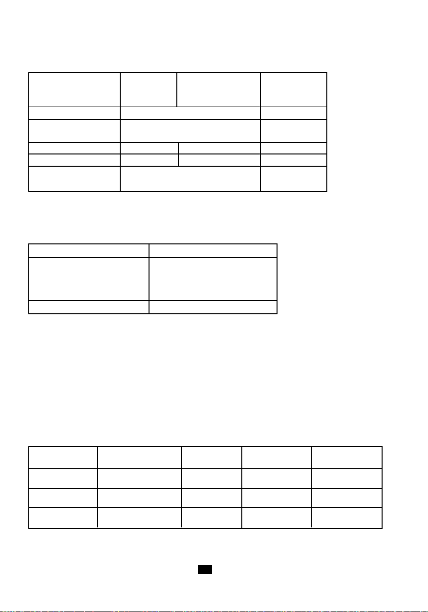
- Duty cycle function
Range % *9999.9 999.99 99.999
- - -
1000.0 100.00 10.000
Resolution 0.1% 1%
Accuracy 0.1% of full scale from 0.2Hz to 50Hz 1% of full scale
0.2% of full scale from 50Hz to 125Hz
Frequency range 0.2 to 125Hz 1 to 125Hz 125 to 500Hz
Measurement time 6s>t>0,5s 1,5s>t>0,5s < 0.5s
Stability ± 1 point from 0.2Hz to 50Hz ± 1 point
± 2 points from 50Hz to 125Hz
* Usable only with the external input.
- Event counter function
Measurement range from 0 to 99999 events
from 1Hz to 10kHz
Counting frequency from 0.1Hz to 10kHz with
range external input in
Accuracy of count ± 1 event
expanded range
6.3 CHARACTERISTICS OF SENSOR
- Measurement conditions
- Optical sensor
Reflecting area: from 10 to 90% of the area of the target.
Surface of the target: in the absence of the reflecting adhesive, the device must not be able to make a
measurement.
Measurement distance: from 1 to 50cm. The maximum distance is valid for a reflecting adhesive tape
having an area of at least 10cm².
Measurement angle: ± 15° from the perpendicular to the reflecting surface.
- variation in the range of use
Quantity of Limit of the range Quantity Typical variation Max. variation
influence of application influenced
Ambient -10 to + 70°C Any quantity ± 30ppm ± 50ppm
temperature measured
Humidity 10% to 90% HR Any quantity < 1.10-5 not significant
Power supply 7 to 10V Any quantity not significant
without condensation measured
measured
5555
Page 56

- optical sensor
Transmission wavelength: 890 nm.
Luminous power transmitted: depends on sighting distance ;
at 1cm => 0,5mW/cm²
at 50cm => 2mW/cm .
Minimum luminous power received: 10µW/cm2.
Ratio of reflecting area to target area: > 5%.
Detection distance: from 1 to 50cm.
Sighting angle from the perpendicular to the target: 0° ± 15°.
6.4 CHARA TERISTICS OF THE ADAPTER AND ITS END FITTINGS
- Mechanical adapter
End fittings: elastomer, Shore hardness 80
Pressure exerted on the moving part: between 2 and 40N.
Maximum speed: 10,000rpm.
Life: approximately 1,000 hours at 3,000rpm at a pressure of 20N.
- Conical end fitting accessory
This end fitting is used for a measurement by contact on the shaft end of a system in rotation.
It is an elastomer cone (max. diameter 15mm) that fits onto the output shaft of the adapter, with quick locking.
Minimum measurement shaft diameter: 5mm.
- Cylindrical end fitting accessory
This end fitting is used for a measurement by contact on the shaft end of a system in rotation.
It is an elastomer cylinder that fits onto the output shaft of the adapter, with quick locking.
It is used to measure the speeds of shafts larger than 5mm in diameter or having flat ends.
- End fitting accessory with wheel
This end fitting is used to measure a linear speed by direct contact with the moving part.
It is a rigid elastomer wheel that fits onto the output shaft of the adapter, with quick locking.
Diameter of the wheel: 30.183mm.
Circumference of the wheel: 10cm ± 0.1mm.
56
Page 57

7. TO ORDER
TACHOMETER C.A 1725 .......................................................................P01174810
- Delivered in its carrying case with 1 FRB F connector, 1 9V battery, 1 set of 15 strips of retroreflecting
film (length 0.1 m), 1 instruction manual on CD-ROM, and one Guide to getting started (printed).
ACCESSORY OF THE C.A 1725
- Mechanical accessories kit .............................................................................................P01174902
comprising 1 mechanical adapter, 1 calibrated wheel, 1 conical end fitting, 1 cylindrical end fitting.
SPARES FOR THE C.A 1725
- End fittings (set of 3) ....................................................................................................... P01174903
comprising 1 calibrated wheel, 1 conical end fitting, 1 cylindrical end fitting.
- 9V battery ........................................................................................................................ P01100732
- Retroreflecting film (15 0.1ms strips) ..............................................................................P01100797
- FRB F connector ..............................................................................................................P01101785
TACHOMETER C.A 1727 .......................................................................P01174830
Delivered in its carrying case with 1 FRB F connector, 1 9V battery, 1 set of 15 strips of retroreflecting
film (length 0.1 m), 1 instruction manual on CD-ROM, T ACHOGRAPH software on CD-ROM and a Guide
to getting started (printed).
ACCESSORIES OF THE C.A 1727
- Mechanical accessories kit .............................................................................................P01174902
comprising 1 mechanical adapter, 1 calibrated wheel, 1 conical end fitting, 1 cylindrical end fitting
- Software of TACHOGRAPH ............................................................................................ P01174835
- USB-A cable <--> USB-B ................................................................................................. P01295293
SPARES OF THE C.A 1727
- End fittings (set of 3) ....................................................................................................... P01174903
comprising 1 calibrated wheel, 1 conical end fitting, 1 cylindrical end fitting.
- 9V battery ........................................................................................................................ P01100732
- Retroreflecting film (15 0.1ms strips) ..............................................................................P01100797
- FRB F connector ..............................................................................................................P01101785
5757
Page 58
Bedeutung der Gerätesymbole
ACHTUNG - Gefahr.
Sobald dieses Gefahrenzeichen auftritt, ist die Anleitung zu Rate zu ziehen.
Das Gerät erfüllt die EMV- und Niederspannungsrichtlinien
(73/23/EWG und 89/336/EWG).
Dieses Gerät muss in der EU gemäß der EC-Richtlinie für Elektro- und Elektronikschrott
WEEE 2002/96/EC entsorgt und recycelt werden.
Sie haben einen Drehzahlmesser C.A 1725 / C.A 1727 erstanden, wir danken Ihnen für Ihr Vertrauen.
Damit die optimale Nutzung des Geräts gewährleistet ist:
• Lesen Sie aufmerksam diese Bedienungsanleitung,
• Beachten Sie genau die Benutzungshinweise.
SICHERHEITSHINWEISE
Berührungslose Messungen:
Vor dem Gebrauch muss das Peilfenster vollkommen sauber sein.
Der minimale Messabstand beträgt 1cm. T eilen die in Bewegung sind sollte man möglichst nicht zu nahe
kommen, sie können für Bediener und Gerät eine Gefahr darstellen.
Messungen mit mechanischen Aufnehmern:
Die Hände müssen in möglichst großer Entfernung vom bewegten Messteil gehalten werden.
Beim Messen nicht zu stark aufdrücken, denn dadurch könnte das bewegte Messteil gebremst werden
und die Messung somit fehlerhaft sein.
Das Messen am Wellenende sollte möglichst genau in der Wellenachse erfolgen.
Messungen mit externem Signaleingang:
Beim Verwenden des externen Anschlusses müssen die Anschlussvorschriften für Zählgeräte
hinsichtlich Industriestörungen berücksichtigt werden.
Geschirmte Drähte mit Masseanschluss ohne Kommutierungseinfluss von Leistungssystemen
verwenden.
Die Störungen dürfen die geräteeigene Hystereseamplitude nicht übersteigen (250mV).
Der externe Eingang ist auf max. 50V Gleichtakt beschränkt.
ACHTUNG :
Die elektrische Masse des externen Eingangs ist im Gerät mit der elektrischen Masse der USBSchnittstelle verbunden.
58
Page 59

INHALTSVERZEICHNIS
1. EINFÜHRUNG ......................................................................... 60
2. BESCHREIBUNG.................................................................... 60
2.1 DREHZAHLMESSER .............................................................................................................. 60
2.2 ANZEIGE ................................................................................................................................ 63
3. BETRIEB.................................................................................. 65
3.1 BERÜHRUNGSFREIES MESSEN ............................................................................................ 65
3.2 BERÜHRUNGSMESSEN ......................................................................................................... 65
3.3 MESSEN MIT EXTERNEM EINGANG ....................................................................................... 66
4. BETRIEB.................................................................................. 68
4.1 MESSEINHEITEN ..................................................................................................................... 68
4.2 MIN/MAX. WERTSPEICHER .................................................................................................... 69
4.3 DAT
4.4 MESSWERTGLÄTTUNG ........................................................................................................ 71
4.5 MANUELLE BEREICHSWAHL ................................................................................................ 71
4.6 ZÄHLER(NUR C.A1727)........................................................................................................ 72
4.7 MESSWERT SPEICHERN (NUR C.A 1727) ............................................................................. 72
4.8 ALARME (NUR C.A 1727) ..................................................................................................... 73
4.9 PROGRAMMIERUNG (NUR C.A 1727) ................................................................................... 74
4.10 DATENAUSWERTUNG AUF DEM PC (NUR C.A 1727) .......................................................... 78
5. INST ANDHALTUNG ................................................................ 79
6. EIGENSCHAFTEN................................................................... 80
6.1 ALLGEMEINE TECHNISCHE DATEN ....................................................................................... 80
6.2 MESSTECHNISCHE EIGENSCHAFTEN ................................................................................... 81
6.3 TECHINISCHE SENSORDATEN...............................................................................................83
6.4 TECHNISCHE DATEN ADAPTER UND ADAPTERAUFSÄTZE ................................................ 84
7. BESTELLANGABEN............................................................... 85
A HOLD ........................................................................................................................... 70
5959
Page 60

1. EINFÜHRUNG
Die Drehzahlmesser C.A 1725 und C.A 1727 wurden speziell für den Industrieeinsatz entwickelt um
berührungslos oder durch mechanische Adapter Drehzahlen von bewegten Teilen zu messen.
Die CHAUVIN ARNOUX Drehzahlmesser bieten über die klassischen Funktionen hinaus viele
verschiedene Möglichkeiten:
- Direktes Ablesen der Messung
- Messen von: Periode, Frequenz, Tastverhältnis, Lineargeschwindigkeit
- Messen mit externem Sensor
- Sonderfunktionen: Smooth, Range, Hold…
- Doppelanzeige, Digital 100 000 Digits und Analog-Bargraph.
Das C.A 1727 ist programmierbar und besitzt eine USB-Schnittstelle. Mit einer spezifischen Software
bietet es zahlreiche Möglichkeiten für Messen, Erfassung, Verarbeitung und Datenauswertung.
2. BESCHREIBUNG
2.1 DREHZAHLMESSER
1 Optischer Sensor
2 Taste
- Speichert den zuletzt angezeigten Digitalwert
- Sperren der Abschalt-Automatik.
Taste nur bei C.A 1727 :
- Beim Programmieren: Verschiebt die gewählte Zahl oder das Komma nach rechts.
3 Taste =>
- Messwertglättung.
Taste nur bei C.A 1727 :
- Beim Programmieren: Erhöht die gewählte Zahl.
4 Taste nur bei C.A 1727 :
- Inbetriebnahme der Summer und Alarmsignale.
- Programmieren der Alarmgrenzwerte.
5 Taste nur bei C.A 1727 :
- Befehl für die S-peicherung der Messwerte.
Taste nur bei C.A 1727 :
- Programmieren des Speicherintervalls.
6 USB-Ausgangsstecker nur bei C.A 1727.
7 Stecker für externen Signaleingang.
60
Page 61

8 Drehschalter.
9 Taste nur bei C.A 1727 :
- Programmieren.
- Programmspeicher initialisieren.
10 Taste nur bei C.A 1727 :
- Ereigniszähler.
Taste nur bei C.A 1727 :
- Programmieren des Skalenfaktors: Koeffizient K.
11 Taste =>
- Manuelle Bereichswahl oder Auto-Range.
- Erweiterung des Messbereichs bei niedrigen Frequenzen.
Taste nur bei C.A 1727 :
- Beim Programmieren: Verringert die gewählte Zahl.
12 Taste :
- Speicherung der Minimal- und Maximalwerte.
- Abschalten des Summers.
Taste nur bei C.A 1727 :
- Beim Programmieren: Verschiebt die gewählte Zahl oder das Komma nach links.
6161
Page 62
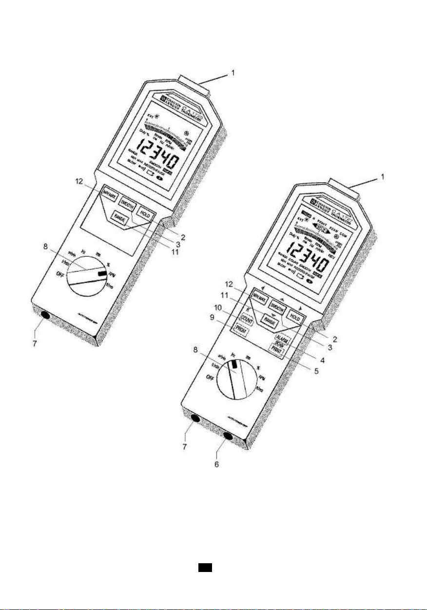
62
Page 63

2.2 ANZEIGE
1 Programmiermodus - nur bei C.A 1727.
2 Grenzwertunterschreitung - nur bei C.A 1727.
3 Koeffizient K Skalenendwert - nur bei C.A 1727.
4 Untere Alarmschwelle - nur bei C.A 1727.
5 Speicherfunktion - nur bei C.A 1727.
6 Obere Alarmschwelle - nur bei C.A 1727.
7 Obere Alarmschwelle überschritten - nur bei C.A 1727.
8 Funktion Intervallspeicherung der Messungen - nur bei C.A 1727.
9 Senden bzw. Empfangen aktiv - nur bei C.A 1727.
10 Blinkanzeige bei Betrieb des Infrarotsensors.
11 Skalenendwert des Analog-Bargraphs (2 bis 200x1000).
12 Analog-Bargraph pro Balkenanzeige.
13 Pfeilspitzen symbolisieren eine Überschreitung des Skalenendwerts.
14 Drehgeschwindigkeit - Revolutions per minute (Englisch)
15 Revolutions: Anzahl Umdrehungen (Englisch) - nur bei C.A 1727.
16 Meter pro Minute: Lineargeschwindigkeit.
17 Hertz: Frequenz.
18 5-stellige Digitalanzeige.
19 Messwertglättung.
20 Anzeigespeicherung des letzten Messwerts.
21 Speicherung vorübergehend unterbrochen.
22 Gerät im Dauerbetrieb.
23 Batterieentladungsanzeige.
24 Min-/Max.Wertspeicher
25 Leuchtanzeige Summer aktiv.
26 Ablesen der gespeicherten Max.Werte.
27 Messbereichserweiterung 0,1Hz.
28 Ablesen der gespeicherten Min.Werte.
29 Unterdrückung der automatischen Bereichswahl.
30 Zählerfunktion nur bei C.A 1727.
31 Millisekunde: Periode.
32 Tastverhältnis.
33 · ft/min: Lineargeschwindigkeit in fuß pro minute (Englisch).
· tr/min: Drehzahl in Umdrehungen pro Minute.
34 Bargraph-Skala.
35 Messen über externen Messeingang.
36 Optischer Sender in Betrieb.
6363
Page 64

64
Page 65

3. BETRIEB
3.1 BERÜHRUNGSLOSE MESSUNGEN
Berührungslose Messungen erfolgen mit dem optischen Sensor im Gerät. Der Sensor befindet sich
vorne im Gerät. Er besitzt einen frequenzmodulierten Infrarotsender.
Vor der Drehzahlmessung muss das drehende Messobjekt entsprechend vorbereitet werden.
Die angepeilte Fläche darf keine störenden Spiegelungen aufweisen, diese könnten als zusätzliche
Impulse der reflektierenden Klebefolie gewertet werden. Bevor man die Messfolie aufklebt, muss
deshalb das Messobjekt gedreht und angepeilt werden. Dabei muss das Messergebnis immer --betragen, andernfalls die Messfläche mit einem mattschwarzen Medium abdecken.
Wenn das Messziel einwandfrei ist, wird eine reflektierende Klebefolie am größtmöglichen Radius des
Teils aufgeklebt. Bei kleinen Messzielen darf die abgedeckte Fläche höchstens 50% der gesamten
Drehfläche ausmachen.
Nun setzt man das Messobjekt in Drehbewegung und peilt es mit der Gerätvorderseite an. Das
entsprechende Messsymbol muss gleichmäßig blinken.
Der Abstand zwischen Sensor und Messobjekt sollte zwischen 1 und 50cm betragen.
Der optimale Messwinkel ist 30° (je 15° rechts und links der Zielachse).
Bei der Messung sehr kleiner Drehzahlen können selbst geringe Bewegungen mit dem Gerät Messfehler
hervorrufen. In diesem Fall sollte das Gerät auf eine stabile Unterlage gestützt werden. An der
Geräteunterseite befindet sich eine Mutter, mit der Drehzahlmesser auf ein Stativ geschraubt werden
kann.
3.2 MESSUNGEN MIT MECHANISCHEN ADAPTERN
Die Berührungsmessung am Wellenende oder von Flächen mit Linearbewegung erfolgt mit Hilfe des
Adapters und 3 Messaufsätzen.
Der Adapter wird vor dem Peilfenster des optischen Sensors angebracht. Es gibt 3 verschiedene
Messaufsätze:
- Ein Elastomer-Konus zum Messen an Wellenenden (Mindestdurchmesser: 5mm).
- Ein Elastomer-Zylinder zum Messen flacher Wellenenden bzw. von Achsen < 5mm.
- Ein Elastomer-Rad zum Messen der Lineargeschwindigkeit (1 Umdrehung des Messrades
= 0,1m).
Die Messaufsätze müssen das Messobjekt gerade so fest berühren, dass sie angetrieben werden
aber nicht rutschen.
Der Adapter wird vor dem Peilfenster an der Vorderseite des Drehzahlmessers befestigt. Der Adapter
rastet automatisch ein.
- Montage
Die drei Adapterzapfen in die drei Hohlräume am Peilfenster des Gerätegehäuses stecken und gegen
den Uhrzeigersinn drehen.
- Demontage
Am Adapter ziehen bis sich die Riegel lösen, dann im Uhrzeigersinn drehen.
6565
Page 66
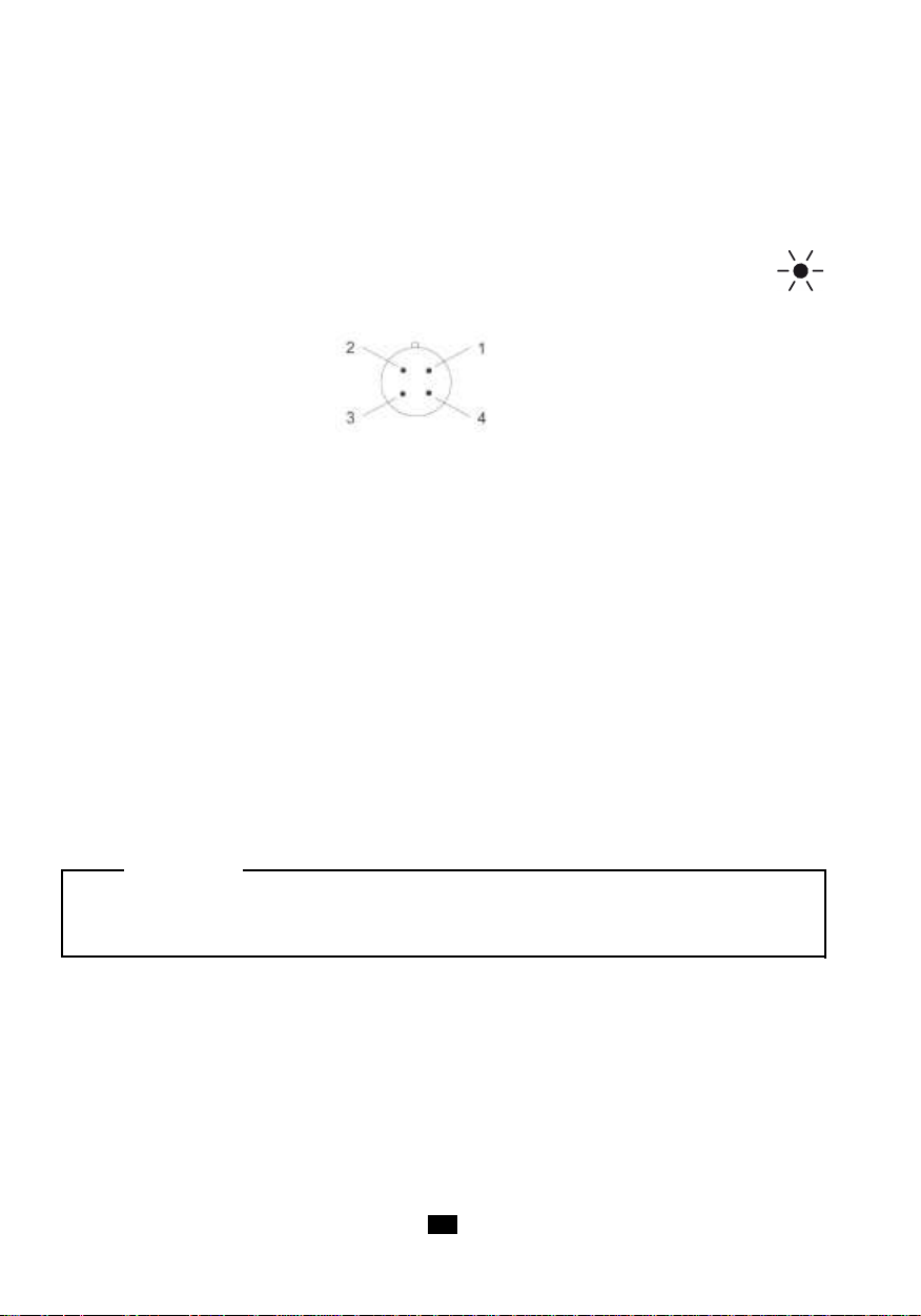
3.3 MESSEN ÜBER EXTERNEN EINGANG
Das Gerät besitzt einen 4-poligen-Stecker zum Messen von Drehzahl, Frequenz, Periode, Tastverhältnis
usw. von externen Gebern.
Die Stifte 1 und 4 müssen kurzgeschlossen werden, damit der Drehzahlmesser die Messung am
externen Eingang vornimmt.
Der Messbetrieb mit externem Eingang wird auf der Anzeige angegeben: Das Sendesymbol
erlischt und EXT wird angezeigt.
Verkabelung
Stecker des 2- Messeingang (max. ± 20VDC)
Drehzahlmessers 3- siehe unten
Anpassen Schaltschwelle an den Signaltyp: Stift 1 und Stift 3 verbinden.
Stifte 1 und 3 nicht angeschlossen
Betriebsart für TTL 0 - 5V Signale.
Ansprechschwelle: +1,1V (bei 1kHz).
Die Hysterese dieses Pegels beträgt 250mV, damit Probleme mit dem in der Industrie oft vorhandenen
Rauschen verhindert werden.
Stifte 1 und 3 angeschlossen
Betriebsart für symmetrisch zur Masse liegende Signale.
Mit dieser Funktion misst man direkt mit einem Magnetgeber mit variabler Reluktanz bzw. direkt am
Ausgang eines Tachogenerators.
Ansprechschwelle: 300mV (bei 1kHz), Hysterese 250mV . Die dem Messsignal überlagerte Störspannung
(Rauschen) muss kleiner als 250mV sein, damit es die Messung beim Überschreiten des Pegels nicht
stört.
ACHTUNG :
Max. Spannung an Eingang 2: nicht über ± 20VDC. Die Masse des externen Sensoreingangs ist
elektrisch mit der Masse des USB-Ausgangs verbunden.
1- Masse
4- mit Stift 1 kurzschließen
66
Page 67
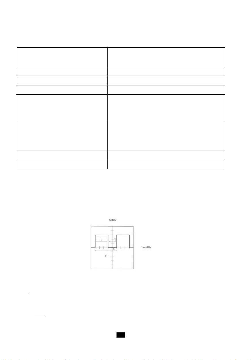
Bei langsamen Messsignalen (ab 0,1Hz) muss über den externen Eingang gemessen werden. Folgende
T abelle gibt einen Überblick der Eigenschaften dieses Eingangs:
Messfrequenzbereich 1Hz bis 10kHz
von 0,1 Hz bis 10 kHz mit erweitertem Bereich
Funktionen Wie mit optischem Sensor
Genauigkeit Wie mit optischem Sensor
Eingangsimpedanz ≥ 75kΩ
Modus Symmetrische Signale 300mV ± 90mV bei 1kHz
Pegel 600mV ± 160mV bei 10kHz
Hysterese 250mV ± 80mV
Modus TTL-Signale 1.1V ± 150mV bei 1kHz
Pegel 2.2V ± 300mV bei 10kHz
Hysterese 250mV ± 80mV
Max.Spannung ± 20V Spitze
Zul. Überlast (1 Sekunde) 250V R.M.S.
Beispiel einer Messung des TASTVERHÄLTNISSES über den EXTERNEN EINGANG
Für Messungen mit dem externen Eingang muss zuerst der mitgelieferte FRB-Stecker mit der
Messsignalquelle verbunden werden, dann wird der Stecker in die mit EXT bezeichnete Buchse gesteckt.
Wir gehen von folgendem Signaltyp aus (siehe Abb.):
Die Signalfrequenz ergibt sich aus der Formel:
1
f =
T
T = 5 x 1ms = 5ms
1
also f = = 200Hz
5.10
-3
6767
Page 68

Der Betriebszyklus ergibt sich aus:
t
Duty =
oder in %. Duty % = x 100
In diesem Beispiel ergibt das:
1
t1 + t
2
t
1
t1 + t
2
3
Duty % = x 100 = 60%
3 + 2
Für die Drehzahlmesser C.A 1725 oder C.A 1727 ist hier folgendes Messverfahren anzuwenden:
1°) Amplitude des Eingangssignals überprüfen. Damit lässt sich die Ansprechschwelle festlegen.
Hier ist die Amplitude größer als +1,1V, es ist daher nicht erforderlich, die Stifte 1 und 3 des
FRB-Steckers zusammenzuschließen.
2°) Den Drehzahlmesser einschalten (Drehschalter auf "%" stellen).
3°) Auf der Anzeige erscheint direkt das oben erläuterte Ergebnis.
Sollte die Anzeige leer bleiben, muss nachgeprüft werden, ob die Amplitude des Messsignals tat sächlich
über der Ansprechschwelle liegt.
4. BETRIEB
4.1 MESSEINHEITEN
Folgende Tabelle gibt die Anzeigemöglichkeiten der einzelnen Funktionen an.
Funktion Anzeige
tr/mn oder RPM 60.000 bis 99999
m/mn (K = 0,1) 6.0000 bis 99999
ft/mn (K = 0,328) 19.680 bis 99999
Hz 1.0000 bis 9999.9
Periode (ms) 0.1000 bis 999.99
Tastverhältnis % 0.1 bis 99.9
Ereigniszähler 0 bis 99999
Bei erweiterter Messung (0,1Hz) über den ext. Eingang sind die jeweiligen Mindestwerte durch 10 zu teilen.
Ein/Aus-Fuktion :
Wenn 5 Minuten lang:
- die Steuertasten des Gerätes nicht betätigt worden sind,
- bei unveränderter Position des Drehschalters,
- bzw. wenn der Digitalausgang nicht abgefragt wurde,
schaltet das Gerät automatisch ab. Ausnahme: Sperren der automatischen Abschaltfunktion bei der
Inbetriebnahme (siehe unten).
Der Drehzahlmesser kündigt das automatische Abschalten mit einem Summton an.
68
Page 69

Sonderfuktionen :
Aufrufen der Sonderfunktionen: Bei Inbetriebnahme des Geräts eine Taste gedrückt halten.
TASTE FUNKTION
keine Inbetriebnahme für 5 Minuten
Inbetriebnahme ohne Abschaltautomatik auf der Anzeige
erscheint
Inbetriebnahme ohne Summer
erscheint nicht
Alle Werte im Programmspeicher initialisieren.
Auf der Anzeige erscheint "Init".
Messen bis 0,1Hz
Auf der Anzeige erscheint SLOW
4.2 MIN-/MAX-AUFZEICHNUNG
Mit dieser Funktion werden die gemessenen Minimal- und Maximalwerte gespeichert.
Mit der T ast geht das Gerät in S peichermodus über . Die Symbole RECORD und werden
angezeigt. Die Abschaltautomatik wird gesperrt.
MIN. Wert
Der ursprüngliche Speicherwert ist OL (OVER LOAD). Sobald die Taste betätigt wird, wird
der Anzeigewert im MIN.-Register gespeichert.
Sobald der im Register gespeicherte Wert unterschritten wird, wird der neue Minimalwert ins MIN.Register übernommen und wird durch ein akustisches Signal von 1kHz bestätigt.
MAX. Wert
Der ursprüngliche Speicherwert ist Null. Sobald der im Register gespeicherte Wert überschritten wird,
wird der neue Maximalwert ins MAX.-Register übernommen und wird durch ein akustisches Signal von
2kHz bestätigt.
Anzeige der gepeicherten MIN-/MAX-Werte
Aufrufen der Speicherwerte in den MIN-/MAX.Registern: mehrmals .
Es werden abwechselnd die Werte MAX, MIN und aktueller Messwert angezeigt.
Der Speichervorgang wird während des Ablesens nicht unterbrochen, der Analog-Bargraph gibt den
momentanen Messwert an.
Anmerkung: Wenn die "SMOOTH"-Funktion aktiviert ist, werden die geglätteten Werte als MIN-. und
MAX-. Werte berücksichtigt.
Beenden der Funktion MIN-/MAX-Aufzeichnung
Zum Beenden der Speicherfunktion entweder die Taste gedrückt halten oder den Drehschalter
drehen.
Hinweis: Im Zählermodus steht die Funktion MIN/MAX nicht zur Verfügung.
6969
Page 70
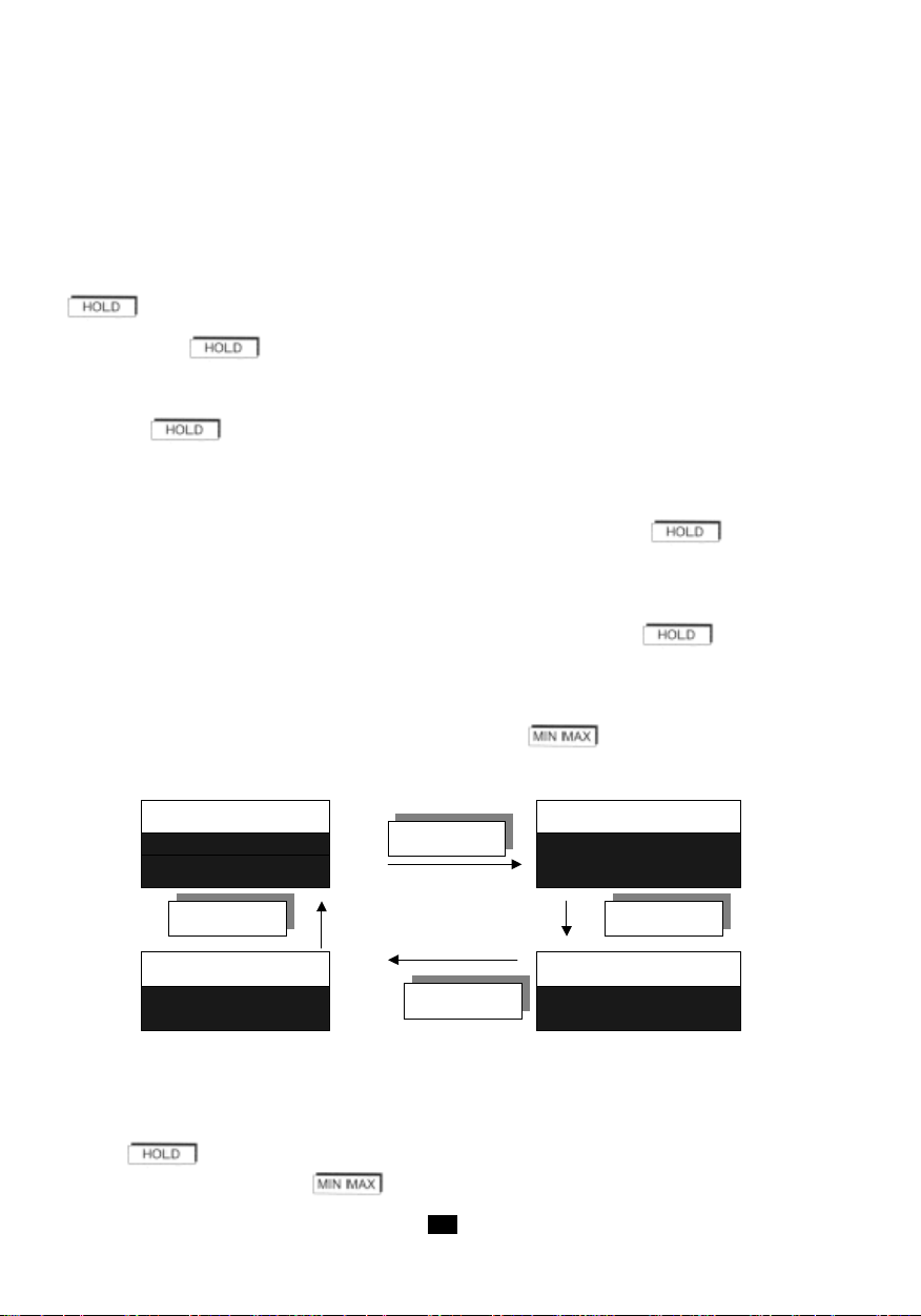
4.3 DA TA-HOLD
Speicher HOLD
MAX. Speicher
HOLD
RECORD PAUSE MAX RECORD PAUSE
Momentane Messung
MIN. Speicher
RECORD PAUSE
MIN RECORD
PAUSE
MIN MAX
MIN MAX
MIN MAX
MIN MAX
Kurz die Taste HOLD drücken (außer Programmiermodus).
Mit der HOLD-Taste wird die Anzeige des letzten angezeigten Messwerts "eingefroren", der AnalogBargraph gibt weiterhin den jeweiligen momentanen Messwert an. Auf der Anzeige erscheint "HOLD".
Zum Wiederherstellen der normalen Anzeige der momentanen Messwerte erneut die Taste HOLD
drücken. HOLD erscheint nicht mehr auf der Anzeige.
im MIN-/MAX-Aufzeichnungsmodus
Wenn die Taste bei RECORD-Anzeige gedrückt wird:
- erscheinen die Symbole HOLD und P AUSE.
- der Speichervorgang wird unterbrochen, in den MIN-. und MAX-. Speichern werden die zuletzt
vor registrierten Werte erhalten.
- die Digitalanzeige gibt den letzten Messwert an, bzw. wenn gerade die MIN-. oder MAX-.Werte
abgerufen wurden, wird der betreffende Wert angezeigt.
- der Analog-Bargraph gibt weiterhin die aktuelle Messung an.
Zum Wiederherstellen des MIN-./MAX-Aufzeichnungsmodus erneut die Taste drücken:
- Die Symbole HOLD und PAUSE werden weiter angezeigt.
- Auf der Anzeige sieht man die laufende Messung bzw. im Ablesemodus den MIN/MAX Speicherwert.
- Die MIN/MAX Funktion ist wieder freigegeben, aber die Speicher wurden nicht reinitialisiert. Die
gespeicherten MIN. und MAX. Werte sind jene, die vor Aktivieren der Funktion
registriert wurden.
Solange die Symbole HOLD und RECORD - PAUSE angezeigt werden, können die Speicherwerte
und die momentanen Messwerte abwechselnd mit der Taste angezeigt werden (Taste
kurz drücken).
Der Analog-Bargraph gibt weiterhin den aktuellen Messwert an.
Für alle Anzeigen gilt:
- Wiederherstellen der Speicherfunktion ohne Reinitialisierung der S peicher mit kurzem Tastendruck
.
- Mit langem Tastendruck beendet das Gerät den Aufzeichnungsmodus.
70
Page 71
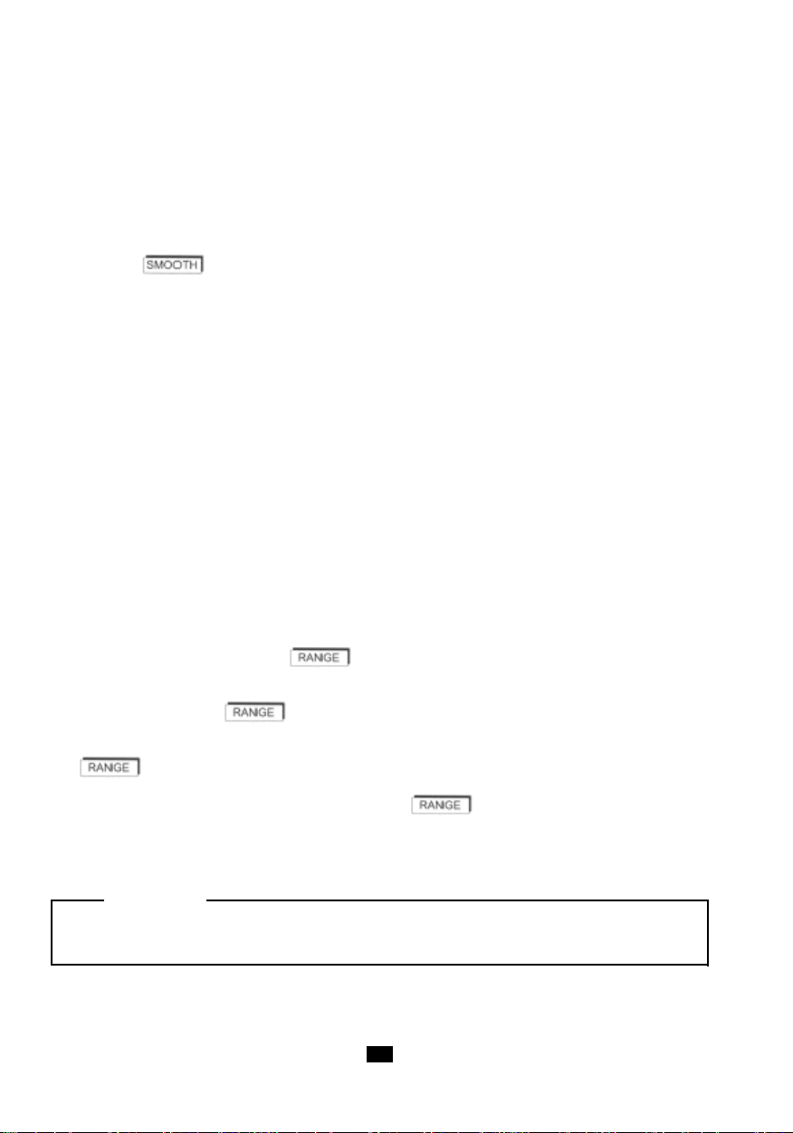
Anwendung:
Wenn das Ablesen der Anzeige des Drehzahlmessers schwierig oder nicht möglich ist, kann man mit
der HOLD Funktion und der MIN-/MAX-. Aufzeichnung die Minimal- und Maximalwerte im Speicher
erhalten.
4.4 MESSWERTGLÄTTUNG
Mit der Taste wird die Messwertglättung aktiviert und SMOOTH erscheint auf der Anzeige.
Der angezeigte Digitalwert ist der gleitende Mittelwert aus den 10 letzten Messwerten (d.h. ungefähr
5 Sekunden).
Der Analog-Bargraph gibt weiterhin den momentanen Messwert an.
Im Modus MIN/MAX. Wertspeicher werden bei aktiver SMOOTH-Anzeige die gefilterten (d.h. geglätteten)
Werte gespeichert.
Wenn der SMOOTH-Modus aktiviert bzw. unterbrochen wird und zugleich die MIN/MAX.
Wertspeicherfunktion läuft, werden die bereits gespeicherten Minimal- und Maximalwerte gelöscht.
Hinweis: Im Zählermodus steht die Funktion SMOOTH nicht zur Verfügung.
4.5 MANUELLE BEREICHSWAHL
Bei der Inbetriebnahme bzw. beim Ändern der gewählten Funktion legt das Gerät automatisch den
optimalen Messbereich fest. Jeder Funktion sind 4 oder 5 Bereiche zugeordnet (mit Ausnahme der
Funktion Tastverhältnis: 2 Bereiche).
Im Auto-Range Modus beträgt der Messumfang der Digitalanzeige 20 000 Messpunkte, die
Skalenendwerte des Analog-Bargraphs sind: 2 - 20 - 200 - 2000 - 20 000 und 200 000.
Im Auto-Range Modus springt die Anzeige in einen größeren Bereich, sobald 20 000 Messpunkte
überschritten werden.
Mit kurzem Tastendruck (< 2s) auf wird der aktuelle Messbereich "eingefroren". Auf der
Anzeige erscheint RANGE. In diesem Fall beträgt die Anzeigekapazität 100 000 Messpunkte.
Mit jedem T astendruck auf gehen die beiden Anzeigen (Analog-Bargraph und Digitalanzeige)
in den nächsthöheren Bereich über. Wenn der höchste Bereich (20 000) erreicht ist, springt man
mit wieder in Bereich 2 zurück.
Zum Verlassen der manuellen Bereichswahl die Taste über 2 Sekunden gedrückt halten.
Hinweis : Wenn der Messwert die Anzeigekapazität übersteigt, erscheint OL auf der Anzeige und der
Pfeil Messbereichsüberschreitung erscheint rechts neben dem Analog-Bargraph.
Achtung :
DIE FOLGENDEN FUNKTIONEN STEHEN NUR AUF C.A 1727 ZUR VERFÜGUNG .
7171
Page 72

4.6 ZÂHLER (NUR C.A 1727)
Der Ereigniszählermodus wird mit der Taste COUNT aufgerufen. Auf der Anzeige erscheint COUNT und
die Messeinheiten werden geändert (siehe Tabelle unten).
Messmodus Modus COUNT
tr/min tr (Umdrehungen)
m/min m (Meter)
RPM REV (Umdrehung)
ft/min ft (Fuß)
Hz /
ms /
Duty % /
Die Symbole Hz, ms und % erlöschen. Es wird keine Messeinheit mehr angezeigt, das Gerät zählt
lediglich die Anzahl empfangener Impulse.
Mit Tastendruck beendet das Gerät den Zählmodus. Wenn die Taste nochmals gedrückt
wird, nimmt das Gerät den unterbrochenen Zählvorgang wieder auf.
Nach 99 999 Ereignissen erscheint OL auf der Anzeige.
Zum Verlassen des Zählmodus nochmals die T aste drücken. Nullstellen des Zählers: T aste .
Hinweis :
- Standardmäßig entspricht die Messdefinition des Geräts für Meter bzw. Fuß ("Feet") dem
Umfang des Messrads, d.h. 0,1m oder 0,328ft. Über den Wert K kann diese Definition anders
programmiert werden.
Im Zählmodus stehen die Funktionen Speichern, Bereichswechsel und Glätten nicht zur Verfügung.
4.7 MESSWERT SPEICHERN (NUR C.A 1727)
Mit der Taste wird der Anzeigewert gespeichert.
- mit HOLD :
Gespeichert wird der zuletzt angezeigte Wert, mit dem Symbol HOLD davor.
- mit MIN-/MAX-Aufzeichnung:
Im Speichermodus RECORD, MIN oder MAX auf dem Bildschirm, werden mit PRINT die W erte MAX, MIN
und der aktueller Messwert gespeichert.
- mit MIN-/MAX-Aufzeichnung + HOLD:
In diesem Modus (Anzeigesymbole RECORD - PAUSE und HOLD) speichert PRINT folgende vier
Parameter:
- HOLD-Wert
- Wert im MIN.Speicher
- Wert im MAX.Speicher
- Aktuellen Messwert
72
Page 73

- mit SMOOTH
Digitaler Messwert >
unterer S chwellwert
(LO AL)
Ohne Wirkung
Digitaler Messwert <
oberer Schwellwert
(HI AL)
Ohne Wirkung
Digitaler Messwert <
unterer S chwellwert
Dauerndes
Alarmsignal 1kHz
Anzeige
Digitaler Messwert >
oberer Schwellwert
Dauerndes
Alarmsignal 1kHz
Anzeige
Wen n der Wert LO AL größer als HI AL
ist, wird der Betrieb um gekehrt. Das
akustische (2kH z) wird im m ittleren
Bereich zwischen den Werten H I AL und
LO AL ausgelöst.
Bei dieser Funktion (Anzeige SMOOTH) wird der geglättete Wert gespeichert.
Die Symbole PRINT und COM werden für die ganze Dauer des Speichervorgangs angezeigt.
Wenn die Scanning-Funktion programmiert wurde (siehe "Speicherintervall"), wird mit der
Taste der Speicherzyklus der Messwerte nach dem programmierten Intervall gestartet. Das
Symbol SCAN wird für die Dauer der Scanning-Funktion angezeigt. Jedes Mal, wenn Daten gespeichert
werden, erscheinen PRINT und COM.
Wenn die Taste nochmals gedrückt wird, werden die letzten Daten gesendet, das Scanning
unterbrochen und die Symbole SCAN, PRINT und COM erlöschen.
Beim 2. Druck auf wird die Funktion abwechselnd gestartet bzw. unterbrochen.
4.8 ALARMSCHWELLEN (NUR C.A 1727)
Wenn Grenzwerte programmiert worden sind, wird mit der Taste (kurz drücken) die
Alarmfunktion aktiviert, das heißt es wird erfasst, wenn die Messung die Grenzwerte über- oder
unterschreitet.
Die Symbol oder , bzw. beide, werden angezeigt (je nach programmiertem Grenzwert).
Überblick über den Alarmbetrieb:
Wenn keine Schwellwerte programmiert wurden, ertönt beim Betätigen der Taste ein
akustisches Signal und der Befehl wird nicht berücksichtigt.
Zum Beenden der Alarmfunktion die Taste nochmals drücken.
7373
Page 74
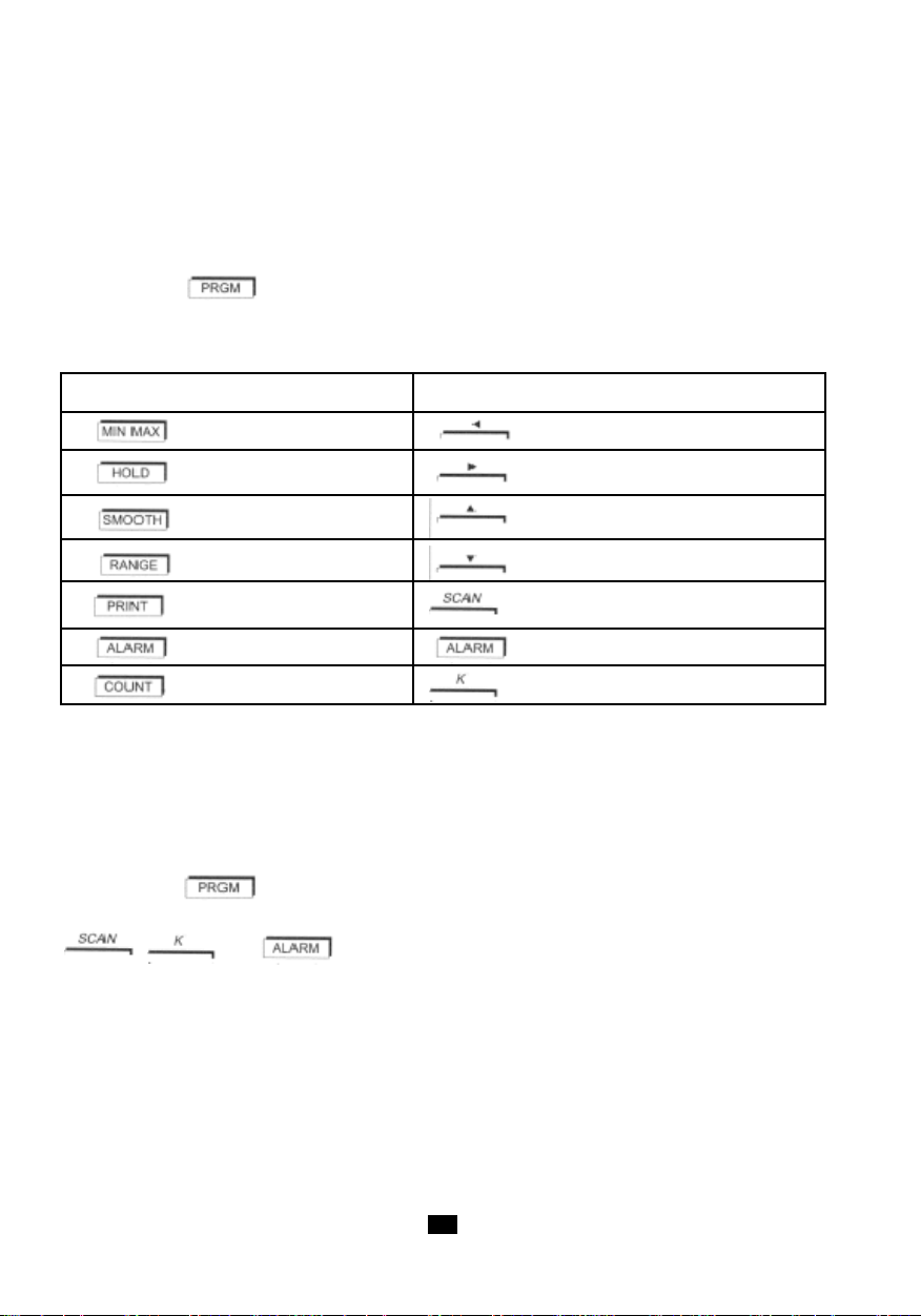
4.9 PROGRAMMIERUNG (NUR C.A 1727)
Auf dem Gerät können vier Werte programmiert werden:
- Untere Alarmschwelle LO AL.
- Oberer Alarmschwelle HI AL.
- Umrechnungsfaktor K.
- Speicherintervall SCAN.
Mit Tastendruck startet C.A 1727 den Programmiermodus und PRGM wird angezeigt.
Im Programmiermodus führt C.A 1727 keine Messungen mehr durch, der Analog-Bargraph erlischt und
der optische Sensor ist in Stillstand.
In diesem Modus gelten die gelb über jeder Taste angeschriebenen Tastenfunktionen.
Tastenfunktion beim Messen Tastenfunktion beim Programmieren
Verschieben nach links
Verschieben nach rechts
Erhöht die gewählte Zahl
Vermindert die gewählte Zahl
Programmieren des Scanning
Programmieren der Alarmschwellen
Programmieren des K-Umrechnungsfaktors
Vorgehensweise
Hier wird die Vorgehensweise für das Programmieren der verschiedenen Speicher des C.A 1727
beschrieben. Diese Etappen gelten für alle Funktionen: Scanning, Grenzwerte und K-Faktor K.
Die Absätze "Alarmgrenzwerte" und "Speicherintervall" beschreiben die Eigenheiten der jeweiligen
Funktion.
Bevor Sie den Programmiermodus aktivieren, wählen Sie mit dem Drehschalter die gewünschte Funktion,
für die Sie Werte programmieren möchten.
Mit Tastendruck wird PRGM angezeigt, der Analog-Bargraph erlischt und auf der Anzeige
erscheint "-----". Als zweite Etappe muss die Funktion gewählt werden, die programmiert werden soll:
: ; oder .
Auf der Anzeige erscheint der gespeicherte Wert, bzw. wenn noch kein Wert programmiert wurde
erscheint "----" (das ist zum Beispiel bei der Erstprogrammierung der Fall oder wenn durch die letzte
Programmierung diese Funktion gesperrt wurde). Gleichzeitig blinkt die linke Ziffer (oder Strich).
Programmierung über 100 000 Punkte (0 bis 99 999). Es gibt 5 mögliche Dezimalstellen für die
Alarmgrenzwerte (K besitzt nur eine mögliche Dezimalstelle und der SCAN-Intervall besitzt keine
Dezimalstelle).
Eingabe eines Werts in den Speicher:
A/ Alle Ziffern der gewünschten Zahl eingeben, ohne Komma.
B/ Eingabe des Kommas an die gewünschte Stelle.
74
Page 75
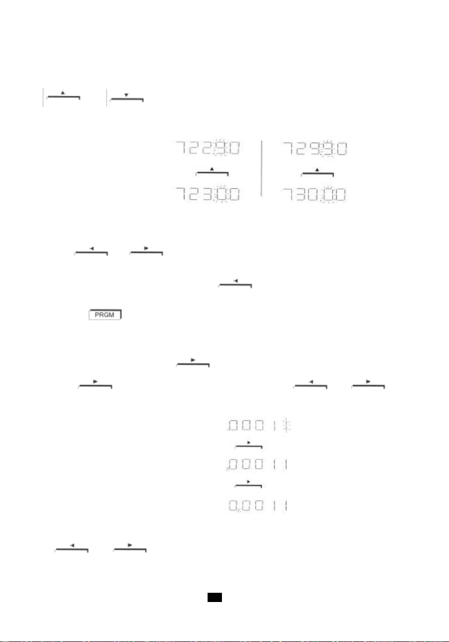
A/ Eingabe einer Zahl ohne Komma :
Bei Strichen: Mit einer Verschiebetaste werden die Striche mit Null, dem alten Speicherwert oder dem
für die gewählte Funktion größt-/kleinstmöglichen Wert besetzt. Die jeweils aktive Ziffer blinkt und wird
mit
2, …) oder nach unten (…2, 1, 0, 9, 8,…) abgeändert wird, werden die Ziffernstellen links davon
automatisch ebenfalls erhöht oder vermindert.
Beispiel:
Wenn beim Programmieren die maximale Anzeigekapazität überschritten wird, erscheinen wieder fünf
Striche anstelle der Zahl.
Die Tasten und verschieben die aktive (blinkende) Ziffer, die eingestellt werden
soll, nach links bzw. rechts.
Wenn die linke Randziffer aktiv ist und die Taste betätigt wird, erscheinen entweder fünf
Striche oder der zuvor gespeicherte Wert.
Bestätigung mit oder einer anderen Programmiertaste (z.B. SCAN).
Wenn die Striche "-----" bestätigt werden, wird die Programmierung unterbrochen und annulliert.
B/ Komma positionieren :
Zum aktivieren des Kommas, die Taste
noch ein Mal drücken, das Komma wird gewählt. Nun kann mit oder das
Komma an die gewünschte Stelle verschoben werden.
bzw. erhöht oder vermindert. Wenn eine Ziffer nach oben (… 7, 8, 9, 0, 1,
1. Anzeige
2. Taste
3. Anzeige
so oft drücken, bis die rechte Randziffer blinkt. Nun
Beispiel:
1. Anzeige
2. Taste
3. Anzeige
4. Taste
5. Anzeige
Wenn das Komma den linken oder rechten Anzeigerand erreicht hat und man neuerlich die
Taste oder drückt, erscheint "-----".
7575
Page 76

Mit den Taste oder (je nachdem, ob man sich am linken oder rechten Rand
befindet) kann das Komma wieder auf die Anzeige geholt werden. Nachdem es fünf Kommastellen gibt,
kann die programmierte Definition genauer sein als die Messdefinition. In diesem Fall wird für die
Erfassung einer Alarmschwellen-Überschreitung immer die tatsächliche Messdefinition herangezogen.
Programmiermodus verlassen sowie bestätigen mit:
- Entweder mit der Taste . Programmiermodus wird verlassen und PRGM erlischt.
- Oder durch Übergang in eine andere Programmierfunktion mit den Taste ,
oder .
- Oder durch Wählen einer anderen Drehschalterposition (außer OFF). Dann geht das Gerät in
Messmodus über. (Bei der Schalterstellung "OFF" kann nicht bestätigt werden und die aktuellen
Werte gehen verloren). Die davor gespeicherten Werte bleiben erhalten.
Für das Abrufen der Speicherdaten wie beim Programmieren vorgehen, die Taste ,
, und dürfen allerdings nicht verwendet werden.
Alarmschwellen (nur C.A 1727)
Sie können zwei Schwellwerte festlegen. Dazu im Programmiermodus die Taste drücken.
Beim ersten Druck der Taste wird angezeigt; nun kann die untere Alarmschwelle
programmiert werden.
Beim zweiten Druck der Taste wird die untere Alarmschwelle (LO AL) bestätigt
und angezeigt; nun kann der obere Schwellwert (HI AL) programmiert werden.
Wenn ein Schwellwert programmiert wurde und die ALARM-Funktion aktiviert wird, erscheint im
Messmodus das entsprechende Symbol auf der Anzeige und der Messwert wird ständig mit dem
Schwellwert verglichen. Bei Über- oder Unterschreitung des Schwellwertes wird das entsprechende
Symbol angezeigt und ein akustisches Signal ertönt (Anleitung zu dieser Funktion im Absatz ALARM).
Die programmierten und aktivierten Schwellwert erscheinen auf dem Analog-Bargraph in Kontrast zur
Messung: Schwarz bei Grenzwertunterschreitung, weiß bei Grenzwertüberschreitung, Blinken (4
Hz) bei Deckungsgleichheit mit dem Schwellwert.
Umrechnungsfaktor K (nur C.A 1727)
Der Umrechnungsfaktor K wird auf den Bruttomesswert angewendet und wandelt diesen in einen
direkt nutzbaren Anzeigewert um.
Beispiele:
- Programmieren eines Übersetzungsverhältnisses. Mit Hilfe des Umrechnungsfaktors kann durch
einfaches Messen am Eingang direkt die Geschwindigkeit am Ausgang einer Untersetzung angezeigt
werden.
- Durchflussmessung. Ein Durchflussmesser gibt alle 2m3 einen Impuls ab. In Hz erhält man direkt die
Durchflussmessung (K = 2) pro Sekunde. Mit COUNT erhält man außerdem das Volumen, das durch die
Leitung geflossen ist.
Programmieren des Faktors K: Im Programmiermodus PRGM die T aste betätigen.
76
Page 77

Wenn ein vom Ursprungswert abweichender Koeffizient programmiert wurde, erscheint im Messmodus
das Symbol K auf der Anzeige. Die Digitalanzeige und der Analog-Bargraph berücksichtigen den
Multiplikatorkoeffizienten K.
Das Symbol K erlischt erst wieder, wenn wieder der ursprüngliche Koeffizient K programmiert wird
(siehe Tabelle unten).
K muss zwischen 99,999 und 0,010 liegen, andere Werte werden nicht berücksichtigt.
Messung Zähler Ursprungswert
K in tr/mn K in tr 1
K in m/min K in m 0.1
K in RPM K in REV 1
K in ft/min K in ft 0.328
K in kHz, ms, % K inImpulszahl 1
Die Umprogrammierung des Faktors K ändert die maximalen Mess- und Anzeigewerte nicht (0,1 bis
10 000Hz und 0 bis 99 999 Punkte).
Folgende Tabelle zeigt die Grenzfrequenzen für die jeweiligen Faktoren K (dabei gehen wir davon
aus, dass die externe Anschlussbuchse verwendet wird). Bei Grenzüberschreitungen erscheint
OL, bei Grenzunterschreitungen "-----".
Messeinheit Programmierter Faktor K
MAX. Freq. am 9999.9Hz 1000Hz
Eingang mit MAX.
Anzeige 99999pts 99999pts
Hz
MIN. Freq. am 0.1Hz 0.1Hz
Eingang mit MIN.
Anzeige 0.0010pts 9999pts
fréq. MAX entrée 10.000Hz 16.666Hz
tr/min oder RPM Eingang mit MAX.
Anzeige 6000.0pts 99999pts
MIN. Freq. am 0.1Hz 0.1Hz
m/min Eingang mit MIN.
Anzeige 0.0600pts 59999pts
Messeinheit Programmierter Faktor K
MAX. Freq. am 10000Hz 50.8Hz
ft/min Eingang mit MAX.
Anzeige 19800pts 99999pts
MIN. Freq. am 0.1Hz 0.1Hz
1ft = 0.3048cm Eingang mit MIN.
1m = 3.281ft Anzeige 0.1980pts 196.86pts
0.01 99.999
0.033 32.81
7777
Page 78

Speicherintervall SCAN (nur C.A 1727)
Die Scanning-Funktion ermöglicht Messungen in einem bestimmten Messtakt bei automatischer
Ergebnisspeicherung. Es ist möglich, bis zu 4000 Punkte.
Programmieren dieser Funktion: Im Programmmodus die Taste betätigen. Das Symbol SCAN
wird angezeigt.
Der programmierte Wert gibt an, in welchem Sekundenabstand die Messwerte gespeichert werden.
Die Grenzwerte sind mind. 10 Sekunden und höchstens 99 999 Sekunden (ca. 27 Stunden).
Im Messmodus startet bzw. unterbricht man den S peichervorgang mit der Taste . Die Symbole
PRINT und SCAN bestätigen, dass der Speichervorgang läuft (siehe "SPEICHERN").
Bei Speicherintervallen von über 5 Minuten wird der optische Sensor zwischen den Messungen
abgeschaltet (das Symbol erlischt) und 2 Sekunden vor der nächsten Messung wieder gestartet.
In der Scanning-Funktion wird die Abschaltautomatik des C.A 1727 gesperrt. Das Symbol wird
angezeigt.
4.10 DATENAUSWERTUNG AUF DEM PC (NUR C.A 1727)
Die Software TACHOGRAPH bietet die Möglichkeit, die Daten im C.A 1727 beidseitig zu verwalten.
Sie erfasst, verarbeitet und verwertet die Messdaten des Drehzahlmessers C.A 1727 und überträgt
die Ergebnisdateien auf die Festplatte eines PCs. Die Software exportiert die Daten in ein EXCELkompatibles Format, damit der Endbenutzer die Ergebnisse beliebig auswerten kann. Außerdem können
die programmierten Geräteparameter übertragen und angezeigt werden.
Die Software TACHOGRAPH bietet Ergebnisauswertung und grafische Darstellung wie zum Beispiel
Mittelwertberechnung, Integralberechnung (Position) und Berechnung der Ableitung (Beschleunigung).
Im Graphfenster kann die Anzeige bearbeitet werden:
- Min. + Text1 hinzufügen, Max. + Text2 hinzufügen, Graph umbenennen.
Für jeden Graph gibt es folgende Anzeigefunktionen:
- Einstellen von Skala, Farben, Hinzufügen von Raster (Fadenkreuz), zwei Cursoren, Bildunterschrift
mit Delta-Anzeige zwischen den Cursoren und + / - Zoom.
Für die Datenerfassung können folgende Parameter festgelegt werden:
- Schnittstelle RS232, Scan, Ableseintervall der Messung, Speicher- und Alarmschwellwerte.
Beispiel für ein Menü am PC-Bildschirm: Dateimenü
78
Page 79

Beispiel für ein Menü am PC-Bildschirm: Hilfemenü
5. INSTANDHALTUNG
Der Drehzahlmesser erfordert außer Batteriewechsel und Gehäusereinigung keine besondere Wartung.
- Werkseinstellung
Das Gerät benötigt keinerlei Einstellungen. Die Messgenauigkeit gewährleistet ein hochstabiler Quarz.
- Reinigung des Gehäuses
Reinigung des Geräts mit einem weichen Lappen und einer Seifenlösung, danach mit klarem Wasser.
Ein schmutziges Peilfenster kann die Sichteigenschaften stark beeinträchtigen und die Messung
verhindern bzw. unstabile Messungen verursachen.
- Reinigen des mechanischen Teils
Reinigung des Geräts mit einem weichen Lappen und einer Seifenlösung, danach mit klarem Wasser.
Alkohol und Lösungsmittel können die Schmierung beeinträchtigen und damit den Adapter
unwiederbringlich beschädigen.
- Batteriewechsel
Wenn das Batteriesymbol auf der Anzeige erscheint, muss die Batterie ausgetauscht werden.
- Stellen Sie den Schalter auf die Position "OFF".
- Das Batteriefach hinten am Gerät öffnen. Die Schraube unter Zuhilfenahme einer Münze oder
ähnlichem lösen.
- Die Batterie entfernen und eine neue Batterie korrekt gepolt einlegen. 9V Alkalibatterie (6LF22)
oder vgl. verwenden.
- Den Deckel schließen und die Schraube mäßig festziehen.
- Lagerung
Wird das Gerät längere Zeit nicht verwendet, muss die Batterie herausgenommen und separat gelagert
werden.
- Messtechnische Überprüfung
Wie auch bei anderen Mess- oder Prüfgeräten ist eine regelmäßige Geräteüberprüfung erforderlich.
Es wird mindestens eine einmal jährlich durchgeführte Überprüfung dieses Gerätes empfohlen. Für
Überprüfung und Kalibrierung wenden Sie sich bitte an unsere zugelassenen Messlabors (Auskunft
und Adressen auf Anfrage), bzw. an die Chauvin Arnoux Niederlassung oder den Händler in Ihrem
Land.
7979
Page 80

- Reparatur
Mit Ausnahme des Batterie- und Sicherungswechsels dürfen Arbeiten am Gerät nur von befugten
Fachleuten vorgenommen werden.
Senden Sie das Gerät bei Reparaturen innerhalb und außerhalb der Garantie an Ihren Händler zurück.
- Garantie
Mit Ausnahme von ausdrücklichen anders lautenden Vereinbarungen ist Garantiezeit zwölf Monate ab
Bereitstellungsdatum des Geräts. Auszug aus den Allgemeinen Geschäftsbedingungen (Gesamttext
auf Anfrage).
Jeglicher Gewährleistungsanspruch erlischt in folgenden Fällen:
- unsachgemäße Benutzung des Gerätes oder Verwendung mit inkomp atiblen anderen Geräten;
- Veränderung des Geräts ohne ausdrückliche Genehmigung des Herstellers;
- Eingriffe in das Gerät durch eine nicht vom Hersteller dazu befugte Person;
- Anpassung des Geräts an nicht vorgesehene und nicht in der Anleitung aufgeführte
Verwendungszwecke;
- Beschädigungen durch Stürze, Stöße oder Überschwemmungen.
6. EIGENSCHAFTEN
6.1 ALLGEMEINE TECHNISCHE DA TEN
- Gerät: Drehzahlmesser mit optischem Sensor, externem Eingang und USB-Schnittstelle
- Funktionen: tr/min, m/min, Hz, ms und Tastverhältnis.
- Aufzeichnung: 4000, Trittfrequenz von 10 bis 99 999s.
- Gehäuse: Polycarbonat, Sensorlinse aus Methacrylat.
- Abmessungen: 21 x 72 x 47mm
- Gewicht: ca. 250g.
- Schutzart: IP51 gemäß IEC 60529 (Ausgabe 92).
- Elektromagnetische Verträglichkeit (EMV):
- Sicherheit: Gemäß IEC 61010-1 Ausg.2 2001
- Stromversorgun: - 9V Alkalibatterie 6LF22 o.vgl.
- Umgebung: - Lagerung: -20 bis +70°C / 95% r.F. max ohne Kondensation.
(nur C.A1727).
Das Gerät erfüllt die EMV-Richtlinien, sowie die Norm EN 61326-1 (Ausg. 97) + A1
(Ausg. 98) + A2 (Ausg. 2001)
- Durchschn. Betriebsdauer: - 250 Messungen von je 5 Minuten mit optischem Sensor.
- 600 Messungen von je 5 Minuten mit externem Eingang.
- Betrieb: 0°C bis + 55°C / 90% r .F. max ohne Kondensation.
80
Page 81
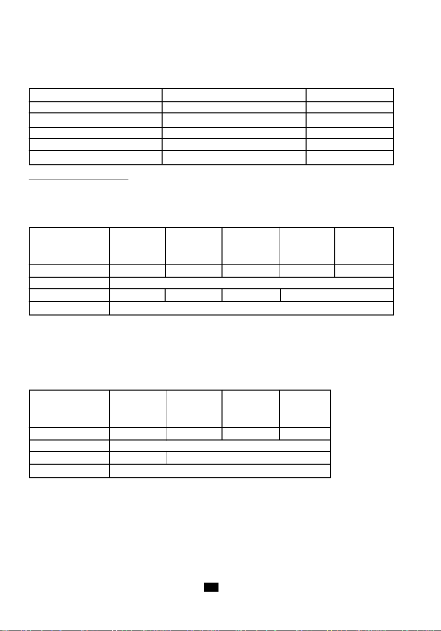
6.2 MESSTECHNISCHE EIGENSCHAFTEN
- Referenzbedingungen
Einflussgröße Referenzbedingungen Toleranzen
Umgebungstemperatur. 23°C ± 3k
Relative Luftfeuchte 45% bis 75% HR
Magnetische Feldstärke < 40A/m bei 50 od. 60Hz
Elektrische Feldstärke < 1V/m bei 50 od. 60Hz
Akku-Spannung 9V ± 0,5V
Einsatz im Referenzbereich
- Optischer Sensor: Mattes Messziel (das in Drehung ohne die Klebefolie keine Messdaten ergibt).
- Externe Buchse: genormtes TTL-Signal 0 - 5V.
- Funktion tr/min
Messbereich* 6.0000 10.000 100.00 1000.0 10000
tr/min - - - - -
9.9999 99.999 999.999 9999.9 99999
Auflösung 0.0006tr/min 0.0006tr/min 0.0006tr/min 0.0006tr/min 0.0006tr/min
Genauigkeit 1.10-4 der Anzeige ± 6 Digits
Messdauer 11s > t > 7s 7s > t > 1s 1s > t > 1s < 0,5s
Stabilität ± 6 Digits
* 6 bis 60tr/min: Nur mit externem Eingang. Bis 10 000tr/min mit Adapter.
- Funktion Hz
Bei Frequenzen über 10kHz, das heißt der oberen Einsatzgrenze, kann es auf diesem Gerät zu
Messfehlern kommen.
Messbereich* 0.1000 10.000 100.00 1000.0
Hz - - - -
9.9999 99.999 999.99 9999.9
Auflösung 0.0004Hz 0.004Hz 0.04Hz 0.4Hz
Genauigkeit 4.10-5 des Werts ± 4 Digits
Messdauer 11s > t > 0,5s < 0,5s
Stabilität ± 4 Digits
* 0,1 bis 1Hz: Nur mit externem Eingang.
8181
Page 82

- Funktion Lineargesschwindigkeit
Mechanischer Adapter mit Messrad (Durchmesser 3,1813cm), wobei K = 0,1 für m/min und K =
0,328 für ft/min.
Messbereich* 0.60000 10.000 100.00 1000.0 10000
m/min - - - - -
9.9999 99.999 999.99 9999.9 59999
Messbereich 1.9680 10.000 100.00 1000.0 10000
ft/min - - - - -
9.9999 99.999 999.99 9999.9 59999
Auflösung 0.0006m/min 0.006m/min 0.06m/min 0.6m/min 6m/min
0.0006ft/min 0.006ft/min 0.06ft/min 0.6ft/min 6ft/min
Genauigkeit 1.10-4 der Anzeige ± 1 Auflösung in m/min
(ohne Messrad) 3.10-4 der Anzeige ± 1 Auflösung in ft/min
Messdauer 11s>t>1,1s 1,1s>t>0,5s < 0,5s
Stabilität ± 1 Auflösung
Genauigkeit 3.10
-3
des Messrades
* 0,6 bis 6m/min und ab 999,99m/min: 1,968 bis 19,680ft/min und ab 3200ft/min nur mit
externem Eingang.
- Funktion Periodendauer
Messbereich * 9999.9 999.99 99.999 9.9999
ms - - - -
1000.0 100.00 10.000 0.1000
Auflösung 0.3ms 0.03ms 0.003ms 0.0005ms
Genauigkeit 1.10-4 der Anzeige ± 5 Digits
Messdauer 11s>t>1,5s 1,5s>t>1,5s 11s>t>1,5s 11s>t>1,5s
Stabilität ± 1 Auflösung
* 1000,0 bis 9999,9ms: Nur mit externem Eingang.
82
Page 83

- Funktion Tastverhältnis
Leistung % *9999.9 999.99 99.999
- - -
1000.0 100.00 10.000
Auflösung 0.1% 1%
Genauigkeit 0.1% des Bereichs von 0.2Hz bis 50Hz 1% des Bereichs
0.2% des Bereichs von 50Hz bis 125Hz
Frequenzbereich 0.2 bis 125Hz 1 bis 125Hz 125 bis 500Hz
Messdauer 6s>t>0,5s 1,5s>t>0,5s < 0.5s
Stabilität ± 1 Digit von 0.2Hz bis 50Hz ± 1 Digit
± 2 Digits von 50Hz bis 125Hz
* Nur mit externem Eingang.
- Funktion Ereigniszähler
Messbereich 0 bis 99999 Ereignisse
1Hz bis 10kHz
Frequenzbereich für die 0.1Hz bis 10kHz mit
Zählung externem Eingang und
Zählergenauigkeit ± 1 Ereignis
erweitertem Bereich
6.3 TECHNISCHE DA TEN DER MESSAUFNEHMER
- Messbedingungen
- Optischer Sensor
Reflektierende Fläche: 10% bis 90% des Zielbereichs.
Zielbereich: Mattes Messziel, das ohne die Klebefolie keine Messdaten ergibt.
Messabstand: 1 bis 50cm. Der maximale Messabstand gilt für eine mind. 10cm² große reflektierende
Klebefolie.
Messwinkel: ±15° zum Lot des Zielbereichs.
- Abweichungen im Betriebsbereich
Einflussgröße Betriebsbereichgrenzen Beeinflusste Typische Max.
Messgröße Abweichung Abweichung
Umgebungstemperatur. -10 bis + 70°C Alle ± 30ppm ± 50ppm
Relative Luftfeuchte 10% bis 90% r.F. Alle < 1.10-5 n.s.
ohne Kondensation Messgrößen
Spannungsversorgung 7 bis 10V Alle n.s.
Messgrößen
Messgrößen
8383
Page 84

- Optischer Sensor
Wellenlänge für die Emission: 890nm.
Leuchtkraft für die Emission: abhängig vom Zielabstand:
1cm => 0,5mW/cm²
50cm => 2mW/cm .
Min. Leuchtkraft für den Empfang: 10µW/cm2.
Verhältnis reflektierende Fläche / gesamte Zielfläche: > 5%.
Erfassungsabstand: 1 bis 50cm
Peilwinkel zum Lot des Zielbereichs: 0° ± 15°.
6.4 TECHNISCHE DA TEN DES ADAPTERS UND DER ADAPTERAUFSÄTZE
- Mechanischer Adapter
Aufsätze: Elastomer, Härte 80 Shores
Druck auf das bewegte Teil: 2 bis 40N.
Max. Drehzahl: 10 000tr/min
Lebensdauer: ca. 1000 Stunden bei 3000tr/min und 20N Druck.
- Zubehör: Konische Drehspitze
Aufsatz zur Berührungsmessung an drehenden Wellenenden.
Der Konus aus Elastomer (max. Durchm. 15mm) wird auf die Adapterachse montiert und rastet sofort
ein.
Mindestdurchmesser der gemessenen Welle: 5mm.
- Zubehör: Zylinderaufsatz
Aufsatz zur Berührungsmessung an drehenden Wellenenden.
Der Zylinder aus Elastomer wird auf die Adapterachse montiert und rastet sofort ein.
Zum Geschwindigkeitsmessen flacher Wellenenden bzw. von Wellenachsen mit Durchm. < 5mm.
- Zubehör: Messrad
Aufsatz zur Berührungsmessung der Lineargeschwindigkeit an bewegten Teilen.
Die Scheibe aus formfestem Elastomer wird auf die Adapterachse montiert und rastet sofort ein.
Raddurchmesser: 30,183mm.
Radabwicklung: 10cm ± 0,1mm.
84
Page 85

7. BESTELLANGABEN
DREHZAHLMESSER C.A 1725 ..............................................................P01174810
Lieferung im Transportkof fer mit 1 FRB F-S tecker, 1 Batterie 9 V, 15 reflektierende Klebestreifen (Länge
0,1 m), 1 Bedienungsanleitung auf CD-ROM und eine Kurzanleitung (auf Papier).
C.A 1725-ZUBEHÖR
- Satz mechanischer Adapter ............................................................................................ P01174902
1 mechanischer Adapter, 1 kalibriertes Messrad, 1 konische Drehspitze, 1 Zylinderaufsatz.
C.A 1725-ERSA TZTEILE
- Aufsätze (3er-Satz) ......................................................................................................... P01174903
1 kalibriertes Messrad, 1 konische Drehspitze, 1 Zylinderaufsatz.
- Batterie 9V ....................................................................................................................... P01100732
- 15 reflektierende Klebestreifen (Länge je 0,1 m)............................................................P01100797
- FRB F Stecker ..................................................................................................................P01101785
DREHZAHLMESSER C.A 1727 ..............................................................P01174830
Lieferung im Transportkof fer mit 1 FRB F-S tecker, 1 Batterie 9 V, 15 reflektierende Klebestreifen (Länge
0,1 m), 1 Bedienungsanleitung auf CD-ROM, 1 Software TACHOGRAPH auf CD-ROM und eine
Kurzanleitung (auf Papier).
C.A 1727-ZUBEHÖR
- Satz mechanischer Adapter ............................................................................................ P01174902
1 mechanischer Adapter, 1 kalibriertes Messrad, 1 konische Drehspitze, 1 Zylinderaufsatz.
- Software TACHOGRAPH auf CD-ROM ........................................................................... P01174835
- Kabel USB-A <--> USB- ................................................................................................... P01295293
C.A 1727-ERSA TZTEILE
- Aufsätze (3er-Satz) ......................................................................................................... P01174903
1 kalibriertes Messrad, 1 konische Drehspitze, 1 Zylinderaufsatz.
- Batterie 9V ....................................................................................................................... P01100732
- 15 reflektierende Klebestreifen (Länge je 0,1 m)............................................................P01100797
- FRB F Stecker ..................................................................................................................P01101785
8585
Page 86

Significato dei simboli utilizzati sull'apparecchio.
ATTENZIONE, rischio di PERICOLO.Consult are il manuale di funzionamento ogni volta che
incontrate questo simbolo
Questa marcatura garantisce la conformità alle direttive europee "Bassa Tensione" e
"Compatibilità Elettromagnetica" (73/23/CEE e 89/336/CEE).
Nell'Unione Europea, questo prodotto è oggetto di una cernita selettiva dei rifiuti per il riciclo
dei materiali elettrici ed elettronici conformemente alla direttiva WEEE 2002/96/EC.
Avete appena acquistato un Tachimetro C.A 1725 / C.A 1727 e vi ringraziamo della vostra fiducia.
Per ottenere le migliori prestazioni dal vostro strumento:
• seguite attentamente le presenti istruzioni per l'uso.
• rispettate le precauzioni d'uso.
PRECAUZIONI D’USO
Per misure senza contatto meccanico:
Prima di utilizzare il tachimetro, verificare che la finestra frontale di mira sia perfettamente pulita.
La distanza di rivelazione minima è di 1 cm; occorre tuttavia evitare la prossimità immediata di qualsiasi
pezzo in movimento, potenzialmente pericoloso per l'operatore e per l'apparecchio.
Per misure con contatto meccanico:
Per quanto possibile allontanare le mani dal pezzo in movimento.
Non esercitare pressioni troppo forti: rischio di falsare la misura a causa della frenatura del pezzo in
movimento.
Per le misure all'estremità dell'albero, posizionarsi per quanto possibile nell'asse dell'albero stesso.
Per misure con entrata esterna:
L'utilizzo della presa esterna richiede il rispetto delle regole sui collegamenti degli apparecchi di conteggio
(Counting), in materia di parassiti industriali.
Impiego di fili blindati collegati ad una massa non sottoposta agli scarti di commutazione dei sistemi di
potenza.
I parassiti ricevuti non dovranno superare l'ampiezza dell'isteresi fissata nell'apparecchio (250mV).
L'entrata esterna è limitata ad un modo comune di 50 volt (massimo).
ATTENZIONE :
La massa elettrica della presa esterna del sensore è comune alla massa elettrica dell'uscita digitale
USB.
86
Page 87

INDICE
1. INTRODUZZIONE .................................................................... 88
2. DESCRIZIONE ......................................................................... 88
2.1 TACHIMETRO ......................................................................................................................... 88
2.2 DISPLAY ................................................................................................................................ 91
3. UTILIZZO .................................................................................. 93
3.1 MISURE SENZA CONT A TTO .................................................................................................. 93
3.2 MISURE CON CONTA TTO ...................................................................................................... 93
3.3 MISURE CON ENTRAT
4. FUNZIONAMENTO .................................................................. 96
4.1 UNITÀ DI MISURA .................................................................................................................. 96
4.2 REGISTRAZIONE MINI:MAXI .................................................................................................. 97
4.3 MANTENIMENTO DEL V ALORE DIGIT ALE ALLA VISUALIZZAZIONE................................... 98
4.4 LIVELLAMENTO DELLA MISURA .......................................................................................... 99
4.5 SCELT A MANUALE DELLA GAMMA...................................................................................... 99
4.6 CONTEGGIO (SOLO C.A1727) ........................................................................................... 100
4.7 REGISTRAZIONE DI MISURA (SOLO C.A 1727).................................................................. 100
4.8 ALLARMI (SOLO C.A 1727) ................................................................................................101
4.9 PROGRAMMAZIONE (SOLO C.A 1727) ..............................................................................102
4.10 SFRUTTAMENTO DEI DA TI SU PC (SOLO C.A 1727).......................................................... 106
5. MANUTENZIONE................................................................... 107
6. CARA TTERISTICHE.............................................................. 108
6.1 CARATTERISTICHE GENERALI............................................................................................ 108
6.2 CARATTERISTICHE METROLOGICHE .................................................................................. 109
6.3 CARATTERISTICHE DEL SENSORE ......................................................................................1
6.4 CARATTERISTICHE DELL ’ADA TTA TORE E RELA TIVI RACCORDI ....................................... 112
7. PER ORDINARE .....................................................................113
A ESTERNA ........................................................................................ 94
11
8787
Page 88

1. INTRODUZZIONE
Appositamente progettati per applicazioni industriali, i tachimetri C.A 1725 e C.A 1727 misurano (a
distanza o mediante contatto) la velocità di rotazione di ogni pezzo in movimento.
Oltre alle funzioni classiche, i tachimetri CHAUVIN ARNOUX offrono molteplici possibilità:
- Lettura diretta della misura
- Misura del periodo, della frequenza, del rapporto ciclico, di velocità lineare
- Misura mediante sensore esterno
- Funzioni speciali: smooth, range, hold…
- Doppia visualizzazione digitale 100 000 punti e bargraph.
Parametrizzabile e munito di un collegamento USB, il C.A 1727, abbinato al suo software specifico,
l'apparecchio offre vaste possibilità di misure, acquisizione, trattamento e sfruttamento dei dati.
2. DESCRIZIONE
2.1 T ACHIMETRO
1 Sensore ottico
2 Tasto
- Memorizzazione dell'ultimo valore digitale visualizzato.
- Inibizione dell'arresto automatico.
Tasto solo su C.A 1727:
- In programmazione: spostamento della selezione della cifra attiva o della virgola verso destra.
3 Tasto =>
- Livellamento delle misure.
T asto solo su C.A 1727:
- In programmazione: incremento della cifra attiva.
4 Tasto solo su C.A 1727:
- Messa in servizio degli allarmi sonori e visivi.
- Programmazione delle soglie d'allarme.
5 T asto solo su C.A 1727:
- Comando di registrazione delle misure in memoria.
Tasto solo su 1727:
- Programmazione della cadenza di registrazione delle misure in memoria.
6 Connettore d'uscita USB solo su C.A 1727:
7 Connettore per entrata esterna.
8 Commutatore rotante.
88
Page 89
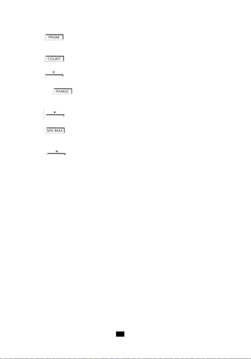
9 Tasto solo su C.A 1727:
- Programmazione.
- Inizializzazione della memoria di programmazione.
10 Tasto solo su C.A 1727:
- Contatore d'eventi.
Tasto solo su C.A 1727:
- Programmazione del fattore di scala: coefficiente K.
11 Tasto =>
- Cambio di gamma (manuale o automatico).
- Estensione del campo di misura in bassa frequenza.
Tasto solo su C.A 1727:
- In programmazione: decremento della cifra.
12 Tasto :
- Registrazione di minimi e massimi.
- Inibizione del buzzer.
Tasto solo su C.A 1727:
- In programmazione: spostamento della selezione della cifra attiva o della virgola verso sinistra.
8989
Page 90

90
Page 91

2.2 DISPLA Y
1 Modo programmazione solo su C.A 1727.
2 Soglia bassa superata solo su C.A 1727.
3 Coefficiente K di fine scala solo su C.A 1727.
4 Funzione soglia bassa solo su C.A 1727.
5 Funzione di scrittura in memoria solo su C.A 1727.
6 Funzione soglia alta solo su C.A 1727.
7 Soglia alta superata solo su C.A 1727.
8 Funzione cadenza di registrazione delle misure in memoria solo su C.A 1727.
9 Emissione o ricezione in corso solo su C.A 1727.
10 Indicatore lampeggiante di funzionamento del sensore ad infrarossi.
11 Valore di fine scala del bargraph (da 2 a 200 x 1000).
12 Visualizzazione analogica mediante bargraph.
13 Punta delle frecce (simbolo del superamento di fine scala).
14 Velocità di rotazione - Rivoluzioni al minuto (in inglese)
15 Rivoluzione: conteggio (Counting) di giri (in inglese) solo su C.A 1727.
16 Metro al minuto: velocità lineare.
17 Hertz: frequenza.
18 Visualizzazione digitale su 5 cifre.
19 Misure in valori livellati.
20 Visualizzazione congelata dell'ultima misura.
21 Registrazione momentaneamente bloccata.
22 Apparecchio in funzionamento permanente.
23 Indicatore d'usura della pila.
24 Registrazione dei MINI/MAXI.
25 Indicatore del buzzer attivo.
26 Lettura della memoria dei MAXI.
27 Ampiezza della misura estesa a 0,1Hz.
28 Lettura della memoria dei MINI.
29 Inibizione del cambiamento di gamma automatica.
30 Funzione di conteggio (Counting) solo su C.A 1727.
31 Millisecondo: periodo.
32 Rapporto ciclico.
33 · ft/min: feet per minute (piede/minuto) - velocità lineare (in inglese).µ
· tr/min: tour par minute (giri/minuto) - velocità di rotazione.
34 Scala fissa graduata.
35 Misura per presa esterna.
36 Emettitore ottico in azione.
9191
Page 92

92
Page 93

3. UTILIZZO
3.1 MISURE SENZA CONT A TTO
La misura senza contatto si effettua mediante il sensore ottico integrato all'apparecchio. Questo
sensore posto nella parte anteriore dell'apparecchio, si compone di un emettitore di luce a infrarossi a
modulazione di frequenza.
Prima di qualsiasi misura, occorre preparare il bersaglio girevole di cui si vuole conoscere la velocità.
Verificare che la superficie mirata non presenti riflessi parassiti che potrebbero essere contati oltre agli
impulsi provenienti dall'adesivo riflettente. A questo scopo prima di incollare l'adesivo che servirà alla
misura, fare ruotare il bersaglio e accertarsi, mirando, che la misura indichi sempre ---. Se così non
fosse occorre coprire tutta la superficie del bersaglio con un supporto nero opaco.
Quando il bersaglio è corretto, incollarvi una striscia d'adesivo riflettente, lungo l'asse formato dal
raggio più lungo possibile. Per i bersagli di piccole dimensioni la superficie coperta dal nastro adesivo
dovrà essere inferiore al 50% della superficie totale della parte girevole.
Mettere in rotazione il bersaglio, mirare a quest'ultimo con la parte anteriore dell'apparecchio, accertarsi
che il simbolo indicante una misura corretta lampeggi regolarmente.
La distanza fra il sensore e il bersaglio sarà compresa fra 1 e 50cm.
L'angolo di misura di 30° (15° da entrambe le parti dell'asse del bersaglio) permette una mira confortevole.
Durante la misura di deboli velocità, certi movimenti (seppure minimi) dell'apparecchio possono generare
instabilità di misura: in questo caso, si raccomanda di posare l'apparecchio su un supporto stabile. Un
dado posto sotto la cassa dell'apparecchio serve precisamente al suo fissaggio su un supporto.
3.2 MISURE CON CONTATTO
L'adattatore meccanico provvisto di 3 raccordi permette la misura mediante contatto all'estremità dell'albero
o su una superficie in movimento lineare.
L'adattatore posto davanti alla finestra di mira del sensore ottico, accetta uno dei 3 seguenti raccordi:
- Un cono d'elastomero la cui punta finale permette la misura all'estremità dell'albero (diametro minimo:
5mm).
- Un cilindro d'elastomero che permette la misura all'estremità dell'albero piano o su assi inferiori a 5mm.
- Una ruota d'elastomero per la misura della velocità lineare (1 giro di ruota = 0,1m).
Il raccordo va premuto sul pezzo in movimento con una forza appena sufficiente al suo avanzamento
senza slittamenti.
L'adattatore si fissa sulla parte anteriore della cassa del tachimetro davanti alla finestra di mira. Un
bloccaggio automatico a fine corsa garantisce il suo corretto posizionamento.
- Montaggio
Per fissare l'adattatore, porre i tre perni interni dell'adattatore all'interno dei tre incavi della finestra di
mira della cassa e ruotare in senso antiorario.
- Smontaggio
Per rimuoverlo, tirare l'adattatore verso l'esterno fino a liberare i bracci di bloccaggio e ruotare l'insieme
in senso orario.
9393
Page 94
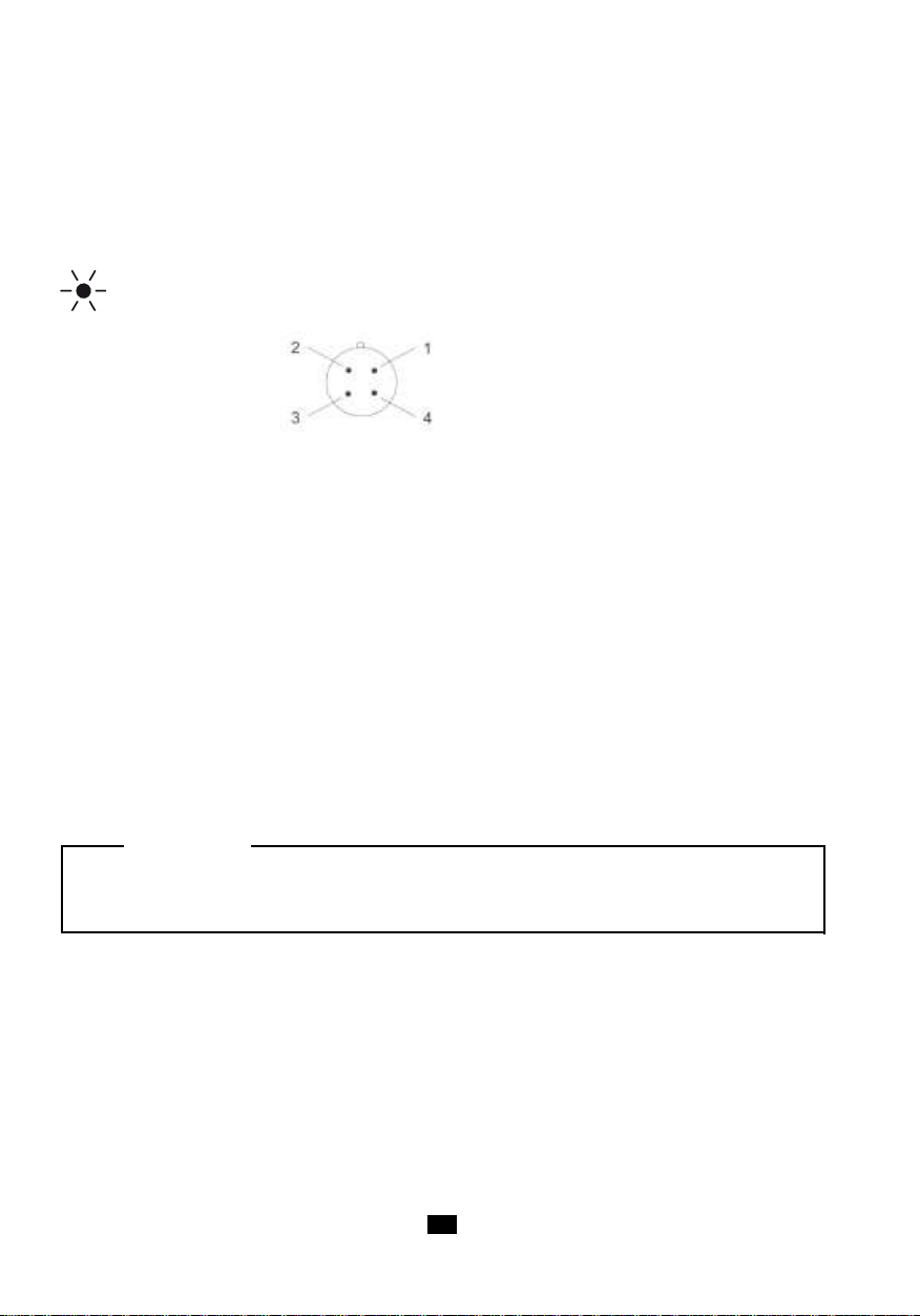
3.3 MISURE CON ENTRA T A ESTERNA
L'apparecchio possiede un connettore a 4 contatti che permettono il raccordo ad una fonte esterna di
cui si vuole conoscere la velocità, la frequenza, il periodo, il rapporto ciclico…
Onde indicare al tachimetro che la presa della misura avviene sull'entrata esterna, è necessario
mettere in corto circuito i poli 1 e 4.
Il funzionamento su entrata esterna è indicato sul display mediante spegnimento del simbolo d'emissione
e visualizzazione di EXT.
Cablaggio
Connettore del 2- entrata misura (± 20VC maxi)
tachimetro visto 3- vedere più avanti
dal lato contatti 4- da mettere in corto circuito il polo n°1
Il raccordo del polo n°1 al polo n°3 permette di adattare la soglia d'attivazione alla natura dei segnali.
Poli 1 e 3 non collegati
Funzionamento previsto per segnali TTL 0 - 5V.
La soglia d'attivazione è fissata a +1,1V (a 1kHz).
Per evitare i problemi dovuti ai rumori spesso presenti in ambiente industriale, la soglia possiede
un'isteresi di 250mV.
Poli 1 e 3 collegati
Funzionamento previsto per segnali simmetrici rispetto alla massa.
Questa funzione permette la misura diretta partendo da un sensore magnetico a riluttanza variabile o
dall'uscita di un alternatore.
La soglia d'attivazione è fissata a 300mV (a 1kHz) con un'isteresi di 250mV. La rumorosità residua
sovrapposta al segnale da misurare dovrà essere inferiore a 250mV per non parassitare la misura al
superamento della soglia.
ATTENZIONE :
La tensione massima applicata all'entrata n°2 non deve superare ± 20Vc. La massa elettrica della
presa entrata esterna è elettricamente collegata alla massa dell'uscita digitale USB.
1- massa
L'utilizzo dell'entrata esterna è necessario per la misura dei segnali lenti a partire da 0,1Hz. La seguente
tabella riassume le caratteristiche di quest'entrata.
94
Page 95

Gamma di frequenza di misura da 1Hz a 10kHz
da 0.1Hz a 10kHz in gamma estesa
Funzioni disponibili in gamma estesa
Precisione idem sensore ottico
Impedenza d‘entrata ≥ 75kΩ
Modo segnali simmetrici 300mV ± 90mV a 1kHz
Soglie 600mV ± 160mV a 10kHz
Isteresi 250mV ± 80mV
Modo segnali TTL 1.1V ± 150mV a 1kHz
Soglie 2.2V ± 300mV a 10kHz
Isteresi 250mV ± 80mV
Tensione massima ± 20V cresta
Sovraccarico ammissibile (1secondo) 250V eff.
Esempio di Misura di RAPPORTO CICLICO su ENTRATA ESTERNA
L'utilizzo dell'entrata esterna richiede il raccordo del connettore FRB (fornito con l'apparecchio) alla
sorgente del segnale da misurare, e l'allacciamento di questo connettore sulla presa marcata EXT.
Si suppone un segnale di tipo simile a quello indicato nella seguente figura:
In questa sede la frequenza del segnale si esprime mediante la formula:
1
f =
T
T = 5 x 1ms = 5ms
1
quindi f = = 200Hz
5.10
-3
9595
Page 96

Il rapporto ciclico si esprime come segue :
t
Duty =
oppure in %. Duty % = x 100
Qui abbiamo :
1
t1 + t
2
t
1
t1 + t
2
3
Duty % = x 100 = 60%
3 + 2
Per effettuare questa misura con i tachimetri C.A 1725 oppure C.A 1727, occorre:
1°) verificare l'ampiezza del segnale entrante nell'apparecchio. Ciò permette di determinare la
soglia da fissare. Qui l'ampiezza è superiore a +1,1V, quindi i poli 1 e 3 della presa FRB non
vanno collegati fra loro.
2°) mettere in marcia il tachimetro portando il commutatore rotante su "%".
3°) il display fornisce direttamente il risultato menzionato più sopra.
Se il display non indica nulla, occorre verificare che il segnale da misurare abbia un'ampiezza superiore
alla soglia d'attivazione.
4. FUNZIONAMENTO
4.1 UNITÀ DI MISURA
La seguente tabella indica la capacità di visualizzazione per ogni funzione.
Funzione Visualizzazione
tr/mn o RPM 60.000 a 99999
m/minuto (K = 0.1) 6.0000 a 99999
ft/minuto (K = 0.328) 19.680 a 99999
Hz 1.0000 a 9999.9
Periodo (ms) 0.1000 a 999.99
Rapporto ciclico % 0.1 a 99.9
Contatore 0 a 99999
In misura estesa a 0,1Hz dall'entrata Ext, i valori minimi sono divisi per 10.
Funzione Marcia /Arresto:
A difetto della sua soppressione alla messa in marcia (vedere più avanti), l'apparecchio si arresta
automaticamente se per 5 minuti non si è prodotto uno dei seguenti eventi:
- Pressione su un tasto,
- Oppure manovra del commutatore rotante,
- Oppure interrogazione dell'uscita digitale.
Prima dell'arresto automatico, il tachimetro emette un bip sonoro.
96
Page 97

Funzioni speciali:
Le seguenti funzioni speciali sono ottenute se si mantiene premuto un tasto alla messa in marcia
dell'apparecchio:
TASTO FUNZIONE
Nessun tasto premuto Messa in marcia per 5 minuti
Messa in marcia permanente
appare sul display
Messa in marcia senza buzzer
Quindi il simbolo non appare
Inizializzazione di tutti i valori contenuti nella memoria
programma.Il display indica "Init".
Misura fino a 0,1Hz
SLOW si accende sul display
4.2 REGISTRAZIONE MINI / MAXI
La funzione registrazione permette la memorizzazione dei valori minimi e massimi delle misure.
Una pressione sul tasto mette l'apparecchio in modo registrazione. I simboli RECORD e
sono visualizzati. La funzione d'arresto automatico è inibita.
Valore MIN
Inizialmente, il valore memorizzato è OL (OVER LOAD). Mediante pressione sul tasto il valore
visualizzato viene memorizzato nel registro MINI.
Ogni misura inferiore a quella contenuta nel registro, viene trasferita nel registro MINI e si ode un bip
sonoro a 1kHz.
Valore MAX
Il valore memorizzato in partenza è zero. Un valore di misura superiore a quello contenuto nel registro
provoca il suo aggiornamento.
Ad ogni modifica del contenuto della memoria MAXI, si ode un bip sonoro di 2kHz.
Lettura delle memorie MINI/MAXI
La visualizzazione dei valori contenuti nei registri MINI e MAXI si effettua mediante pressioni successive
su .
La visualizzazione circolare indica successivamente MAXI, MINI e il valore della misura corrente.
La registrazione prosegue durante la lettura mentre il bargraph indica la misura istantanea.
NB: se la funzione "SMOOTH" è attivata, i MAXI e MINI sono determinati partendo dai valori filtrati.
Arresto della funzione registrazione MINI / MAXI
L'arresto della funzione Registrazione si ottiene mediante una pressione lunga sul tasto ,
oppure mediante rotazione del commutatore.
Osservazione: La funzione MINI/MAXI non è disponibile in modo conteggio.
9797
Page 98

4.3 MANTENIMENTO DEL V ALORE DIGIT ALE ALLA VISUALIZZAZIONE
Memoria HOLD
Memoria MAX
HOLD
RECORD PAUSE MAX RECORD PAUSE
Misura istantanea
Memoria MINI
RECORD PAUSE
MINI RECORD
PAUSE
MINI MAXI
MINI MAXI
MINI MA
XI
MINI MAXI
Mediante pressione breve sul tasto HOLD (fuori modo programmazione).
La pressione su HOLD permette di congelare la visualizzazione digitale sull'ultima misura visualizzata
mentre il bargraph continua a indicare il valore istantaneo della misura. La visualizzazione indica HOLD.
Una nuova pressione sul tasto HOLD ripristina la visualizzazione delle misure istantanee e HOLD
sparisce dal display.
in modo di registrazione "MINI / MAXI"
Quando si preme il tasto mentre RECORD è visualizzato:
- I simboli HOLD e P AUSE si visualizzano.
- La registrazione si ferma e i valori contenuti nelle memorie MINI e MAXI sono gli ultimi valori prima
di .
- Il display digitale indica il valore dell'ultima misura, oppure il valore MINI o MAXI se l'apparecchio
era in rilettura di questi valori.
- Il bargraph continua a indicare la misura corrente.
Una nuova pressione sul tasto prosegue la registrazione di MINI e MAXI:
- I simboli HOLD e P AUSE rimangono visualizzati.
- Il display indica la misura in corso o il contenuto della memoria MINI/MAXI in rilettura.
- L'apparecchio è di nuovo in funzione MINI/MAXI ma le memorie non sono state reinizializzate e
contengono i valori MINI e MAXI presenti prima di .
Quando i simboli HOLD e RECORD-PAUSE sono visualizzati, è sempre possibile visualizzare, in maniera
circolare, i valori delle memorie e della misura istantanea mediante pressioni brevi sul tasto .
Il bargraph indica sempre il valore della misura corrente.
Qualunque sia la visualizzazione in corso:
- Una pressione breve sul tasto
- Una pressione lunga sul tasto stoppe l‘enregistrement.
Applicazione:
Quando si utilizza il tachimetro in un luogo in cui la lettura del display è difficile o impossibile, l'utilizzo
della funzione HOLD con la registrazione MINI / MAXI permette di conservare in memoria il valore
ripristina la registrazione senza reinizializzare le memorie.
(minimo e massimo) raggiunto.
98
Page 99

4.4 LIVELLAMENTO DELLA MISURA
Una pressione sul tasto attiva il livellamento della misura (SMOOTH visualizzato). Il valore
digitale indicato è allora il risultato di una media fluttuante calcolata sulle ultime 10 misure (ossia 5
secondi circa).
Il bargraph indica sempre la misura istantanea.
In modo registrazione MINI MAXI, se il simbolo SMOOTH è visualizzato, i valori registrati sono quelli filtrati
(livellati).
La messa in funzione (o l'arresto) del modo SMOOTH durante una registrazione MINI MAXI cancella i
valori MINI e MAXI già stoccati.
Osservazione: La funzione SMOOTH non è attiva durante il conteggio.
4.5 SCEL T A MANUALE DELLA GAMMA
Alla messa in marcia, o al cambiamento di funzione, l'apparecchio seleziona automaticamente la gamma
di misura più appropriata. Ogni funzione possiede 4 o 5 gamme, tranne la funzione di rapporto ciclico (2
gamme).
In funzionamento automatico, il display digitale ha una capacità di visualizzazione di 20 000 punti e la
fine della scala del bargraph può prendere i valori: 2 - 20 - 200 - 2000 - 20 000 e 200 000.
In modo automatico, il display digitale passa su una gamma superiore quando
si raggiungono 20 000 punti.
Una prima pressione breve (< 2s) sul tasto congela la gamma di misura in corso. RANGE
appare sul display. L'indicatore digitale ha allora una capacità di visualizzazione di 100 000 punti.
Ogni nuova pressione sul tasto incrementa le due visualizzazioni (bargraph e digitale)
sulla gamma superore. Arrivato alla gamma più alta (20 000) il tasto riporta l'apparecchio
sulla gamma 2.
Per uscire dal modo cambio manuale della gamma, premere il tasto più di 2 secondi.
Osservazione:
Se il valore della misura è superiore alla capacità di visualizzazione, il display indica OL e la freccia di
superamento della gamma appare a destra del bargraph.
ATTENZIONE:
LE FUNZIONI DESCRITTE NEI PARAGRAFI SEGUENTI SONO DISPONIBILI SOLO SUL C.A 1727.
9999
Page 100
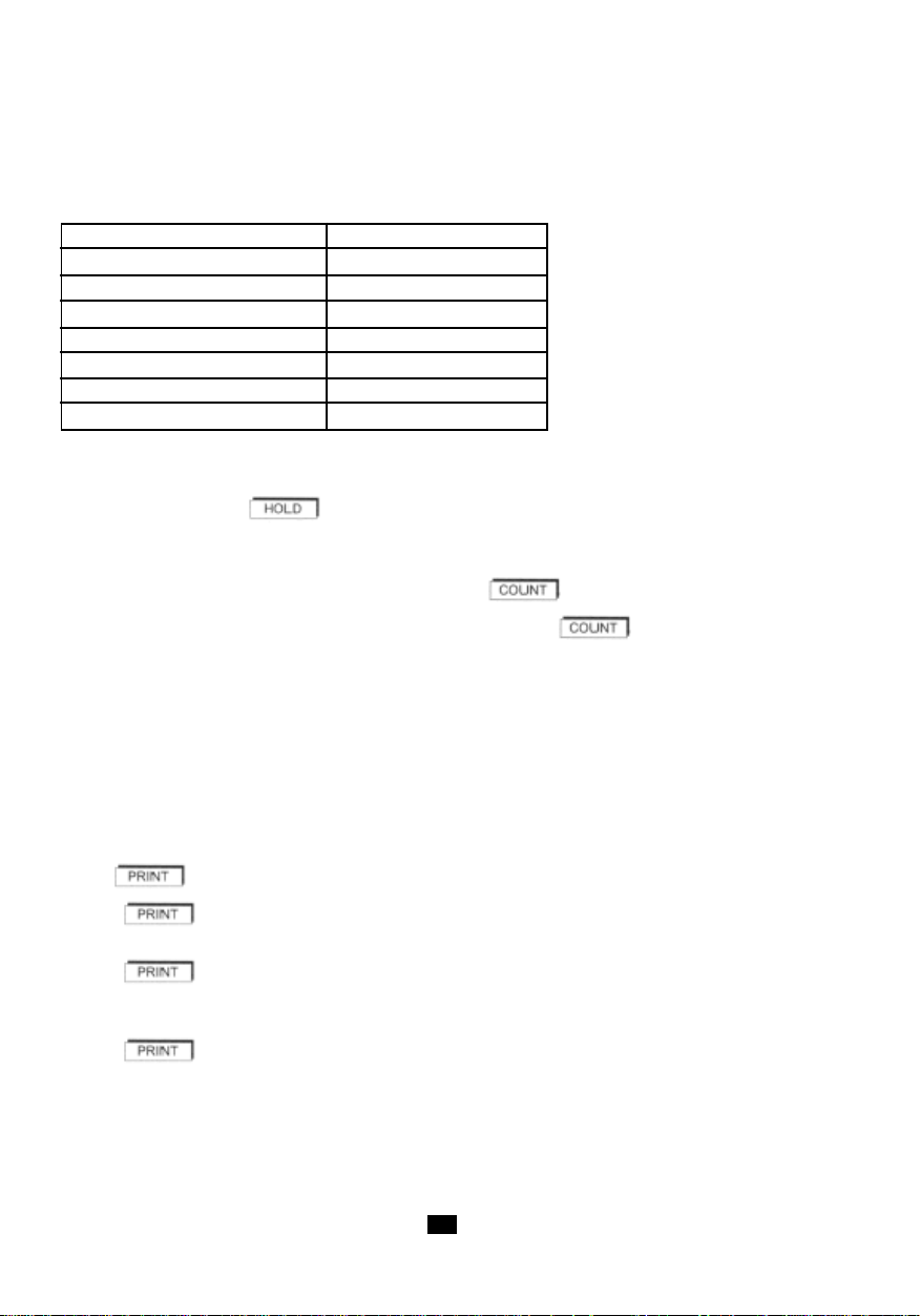
4.6 CONTEGGIO (SOLO C.A 1727)
Premete il tasto COUNT per mettere l'apparecchio in modo conteggio (Counting) d'eventi. COUNT
appare sul display e le unità di misura sono modificate (osservare più avanti la tabella).
Modo di misura Modo COUNT
tr/min giri (giro)
m/min m (metro)
RPM REV (rivoluzione)
ft/min ft (piede)
Hz /
ms /
Duty % /
I simboli Hz, ms e % scompaiono, nessuna unità di misura è visualizzata; l'apparecchio conta solo il
numero d'impulsi ricevuti.
Una pressione sul tasto blocca il conteggio. (Counting) Una seconda pressione riattiva il
conteggio (Counting) momentaneamente bloccato.
In capo a 99 999 eventi, la visualizzazione passa su OL.
Per uscire dal conteggio(Counting) basta premere il tasto una seconda volta. L'azzeramento
del contatore si ottiene mediante 2 pressioni successive sul tasto .
Osservazioni:
- In modo standard, l'apparecchio conta i metri o i piedi ("feet") con una definizione di misura u
guale alla circonferenza del raccordo utilizzato, ossia 0,1m o 0,328ft. E' possibile modificare
questa definizione cambiando il valore di K.
- In modo (Counting), le funzioni registrazione, cambio di gamma e livellamento non sono disponibili.
4.7 REGISTRAZIONE DI MISURA (SOLO C.A 1727)
Il tasto permette la registrazione del valore visualizzato.
- con HOLD :
La registrazione sarà l'ultimo valore visualizzato preceduto da HOLD.
- con registrazione MIN/MAX :
Quando l'apparecchio è in modo registrazione RECORD, MINI o MAXI sullo schermo, il comando PRINT
registra il valore MINI, MAXI e la misura corrente.
- con registrazione MIN MAX + HOLD :
In questo modo (simboli RECORD - PAUSE e HOLD visualizzati), il comando PRINT registra i quattro
seguenti parametri:
- Il valore HOLD
- Il valore contenuto nel registro MINI
- Il valore contenuto nel registro MAX
- Il valore della misura corrente.
100
 Loading...