

Page 1

ENGLISH User Manual
■
THERMO-HYGROMETER
1246
DATA LOGGER
Page 2
Statement of Compliance
Chauvin Arnoux®, Inc. d.b.a. AEMC® Instruments certifies that
this instrument has been calibrated using standards and
instruments traceable to international standards.
We guarantee that at the time of shipping your instrument has
met its published specifications.
An N.I.S.T. traceable certificate may be requested at the
time of purchase, or obtained by returning the instrument to
our repair and calibration facility, for a nominal charge.
The recommended calibration interval for this instrument is 12
months and begins on the date of receipt by the customer. For
recalibration, please use our calibration services. Refer to our
repair and calibration section at www.aemc.com.
Serial #:
Catalog #: 2121.73
Model #: 1246
Please fill in the appropriate date as indicated:
Date Received:
Date Calibration Due:
Chauvin Arnoux®, Inc.
®
d.b.a AEMC
www.
aemc.com
Instruments
2 Thermo-Hygrometer Data Logger Model 1246
Page 3

CONTENTS
PRECAUTIONS ..................................................................................................................................................................... 4
RECEIVING YOUR SHIPMENT ............................................................................................................................................. 5
ORDERING INFORMATION .................................................................................................................................................. 5
1. GETTING STARTED ......................................................................................................................................................... 6
1.1. Battery Installation ................................................................................................................................................... 6
1.2. Instrument Components .......................................................................................................................................... 7
1.3. Instrument Functions ............................................................................................................................................... 7
1.4. Turning the Instrument ON/OFF.............................................................................................................................. 8
1.5. Function Buttons ..................................................................................................................................................... 8
1.6. Display .................................................................................................................................................................... 8
2. SETUP ............................................................................................................................................................................... 9
2.1. DataView® Installation ............................................................................................................................................. 9
2.2. Connecting the Instrument to a Computer .............................................................................................................. 9
2.3. Instrument Date/Time ............................................................................................................................................ 10
2.4. Auto OFF .............................................................................................................................................................. 10
2.5. Temperature Units ................................................................................................................................................ 10
2.6. Alarms ................................................................................................................................................................... 10
3. STANDALONE OPERATION .......................................................................................................................................... 11
3.1. Making Measurements .......................................................................................................................................... 11
3.1.1. HOLD Function .................................................................................................................................... 11
3.1.2. MAX MIN Function ............................................................................................................................... 11
3.2. Recording Measurements ..................................................................................................................................... 12
3.3. Alarms ................................................................................................................................................................... 12
3.4. Errors .................................................................................................................................................................... 12
4. DATAVIEW ...................................................................................................................................................................... 13
5. TECHNICAL CHARACTERISTICS ................................................................................................................................. 14
5.1. Reference Conditions ............................................................................................................................................ 14
5.2. Electrical Specifications ........................................................................................................................................ 14
5.2.1. Temperature Measurement .................................................................................................................. 14
5.2.2. Humidity Measurem ent ......................................................................................................................... 14
5.2.3. Dew Point Measurement ...................................................................................................................... 15
5.2.4. Psychometric Diagram ......................................................................................................................... 15
5.2.5. Influence of Temperature on the Relative Humidity Measurement ...................................................... 16
5.2.6. Response Time .................................................................................................................................... 16
5.3. Memory ................................................................................................................................................................. 16
5.4. USB ....................................................................................................................................................................... 16
5.5. Bluetooth ............................................................................................................................................................... 17
5.6. Power Supply ........................................................................................................................................................ 17
5.7. Environmental Conditions ..................................................................................................................................... 17
5.8. Mechanical Specifications ..................................................................................................................................... 17
5.9. Compliance with International Standards .............................................................................................................. 17
5.10. Electromagnetic Compatibility (CEM) .................................................................................................................. 17
6. MAINTENANCE .............................................................................................................................................................. 18
6.1. Cleaning ................................................................................................................................................................ 18
6.2. Battery Replacement ............................................................................................................................................. 18
6.3. Firmware Update ................................................................................................................................................... 18
REPAIR A
TECHNICAL AND SALES ASSISTANCE .......................................................................................................................... 19
LIMITED WARRANTY ......................................................................................................................................................... 20
ND CALIBRATION ............................................................................................................................................... 19
Thermo-Hygrometer Data Logger Model 1246 3
Page 4
Thank you for purchasing the Thermo-Hygrometer Model 1246. For best results from your instrument:
read these operating instructions carefully,
comply with the precautions for use.
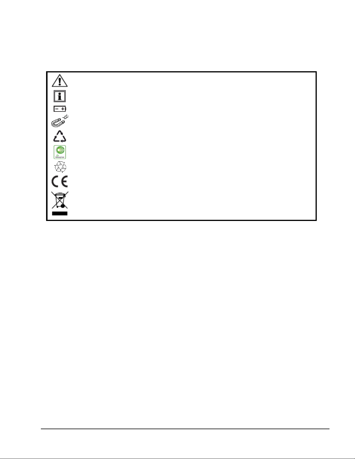
WARNING, risk of DANGER! The operator must refer to these instructions whenever this
danger symbol appears.
I
nformation or useful tip.
attery.
B
et.
Magn
he product has been declared recyclable after analysis of its life cycle in accordance with
T
the ISO14040 standard.
A
EMC has adopted an Eco-Design approach in order to design this appliance. Analysis of
the complete lifecycle has enabled us to control and optimize the effects of the product on
the environment. In particular this appliance exceeds regulation requirements with respect
to recycling and reuse.
I
ndicates conformity with European directives and with regulations covering EMC.
ndicates that, in the European Union, the instrument must undergo selective disposal in
I
compliance with Directive WEEE 2002/96/EC. This instrument must not be treated as
household waste.
Precautions
This instrument is compliant with safety standard IEC 61010-2-030, for voltages up to 5V with respect to ground.
Failure to observe the following safety instructions may result in electric shock, fire, explosion, and damage to
the instrument and/or the install ati on in which it is locat ed.
The operator and/or the responsible authority must carefully read and clearly understand all precautions
to be taken prior to using the instrument. Thorough knowledge and awareness of electrical hazards ar
es
sential when using this instrument.
Observe the conditions of use, including temperature, relative humidity, altitude, pollution degree, and
l
ocation of use.
Do not use the instrument if it appears damaged, incomplete, or improperly closed.
Before each use, check the condition of the housing and accessories. Any item on which the insulation
is deteriorated (even partially) must be set aside for repair or disposal.
All troubleshooting and metrological checks must be done by accredited personnel.
e
4 Thermo-Hygrometer Data Logger Model 1246
Page 5

Receiving Your Shipment
Upon receiving your shipment, make sure that the contents are consistent with the packing list. Notify your
distributor of any missing items. If the equipment appears to be damaged, file a claim immediately with the
carrier and notify your distributor at once, giving a detailed description of any damage. Save the damaged
packing container to substantiate your claim.
Ordering Information
Thermo-Hygrometer Data Logger Model 1246…...……………..….….…………………….…...... Cat. #2121.73
Includes soft carrying pouch, three AA alkaline batteries, 6 ft. USB cable, quick start guide, USB drive
with DataView
R
eplacement Parts:
Cable – Replacement 6 ft. (1.8m) USB…………….……………………....................…............... Cat. #2138.66
Pouch – Replacement Carrying Pouch……………………....…..……………..……..................... Cat. #2118.65
ccessories:
A
Multifix Universal Mounting System …...……………..……………..…......................................... Cat. #5000.44
Adapter – US Wall Plug to USB……………....…………………….…...………..…….….….…...... Cat. #2153.78
Shock Proof Housing………………………………………......…………...………..……....…..…… Cat. #2122.31
Case – General Purpose Carrying Case ………………........…….…...………..……….....……… Cat. #2118.09
®
software and user manual.
or the accessories and replacement parts, visit our web site: www.aemc.com
F
Thermo-Hygrometer Data Logger Model 1246 5
Page 6
1. GETTING STARTED
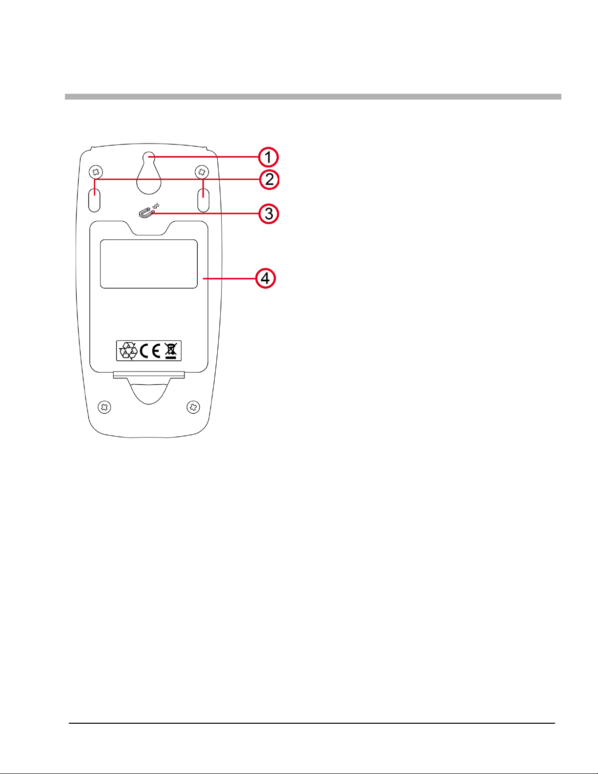
1.1. Battery Installation
The instrument accepts three AA or LR6 alkaline batteries.
1. “Tear-drop” notch to hang instrument
2. Non-skid pads
3. Magnets for mounting to a metallic surface
4. Battery compartment cover
To change the batteries:
1. Press the tab of the battery compartment cover and lift it clear.
2. Remove the battery compartment cover.
3. Insert the new batteries, ensuring correct polarity.
4. Close the battery compartment cover; ensuring it is completely and correctly closed.
6 Thermo-Hygrometer Data Logger Model 1246
Page 7
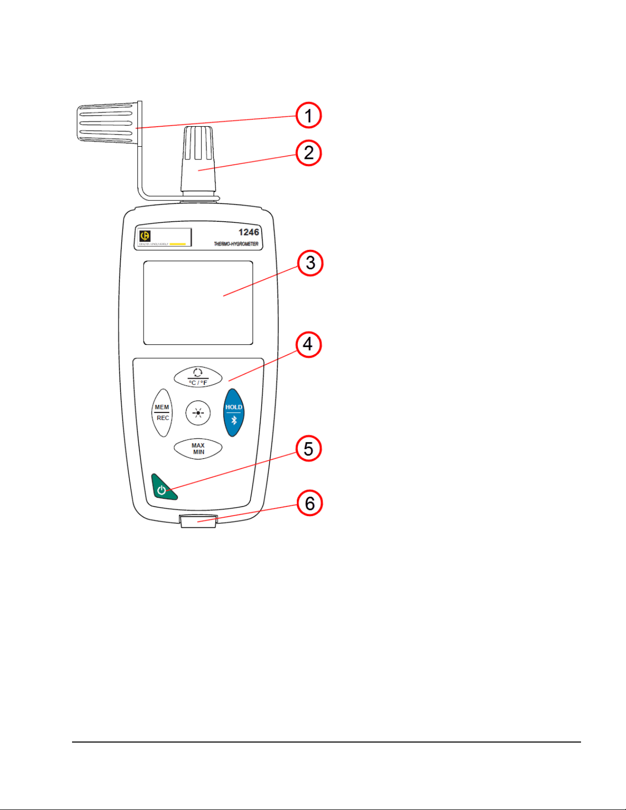
1.2. Instrument Components
1. Sensor protective cap
4. Keypad
2. Temperature/humidity sensor
3. Backlit LCD display
1.3. Instrument Functions
The Model 1246 measures temperatures from 14 to 140°F (-10 to 60°C) and relative humidity from 3 to 98%
RH. This standalone instrument can:
Display temperature measurements in °C or in °F
Display a minimum and maximum in a specified period
Record measurements
Communicate with a computer via Bluetooth or USB cable
Dat
aView with the Data Logger Control Panel software can be installed on a computer to allow you to configure
the instrument, view measurements in real time, download data from the instrument, and create reports.
Thermo-Hygrometer Data Logger Model 1246 7
5. ON/OFF button
6. Type B micro-USB connector
Page 8
1.4. Turning the Instrument ON/OFF
Short press (<2 seconds) cycles through the following pairs of measurements:
Short press records the measurement and date/time.
Long press starts/stops a recording session.
Turns on backlight.
Short press freezes the display.
Long press activates/deactivates Bluetooth.
Short press enters MAX MIN mode; the current values continue to be displayed.
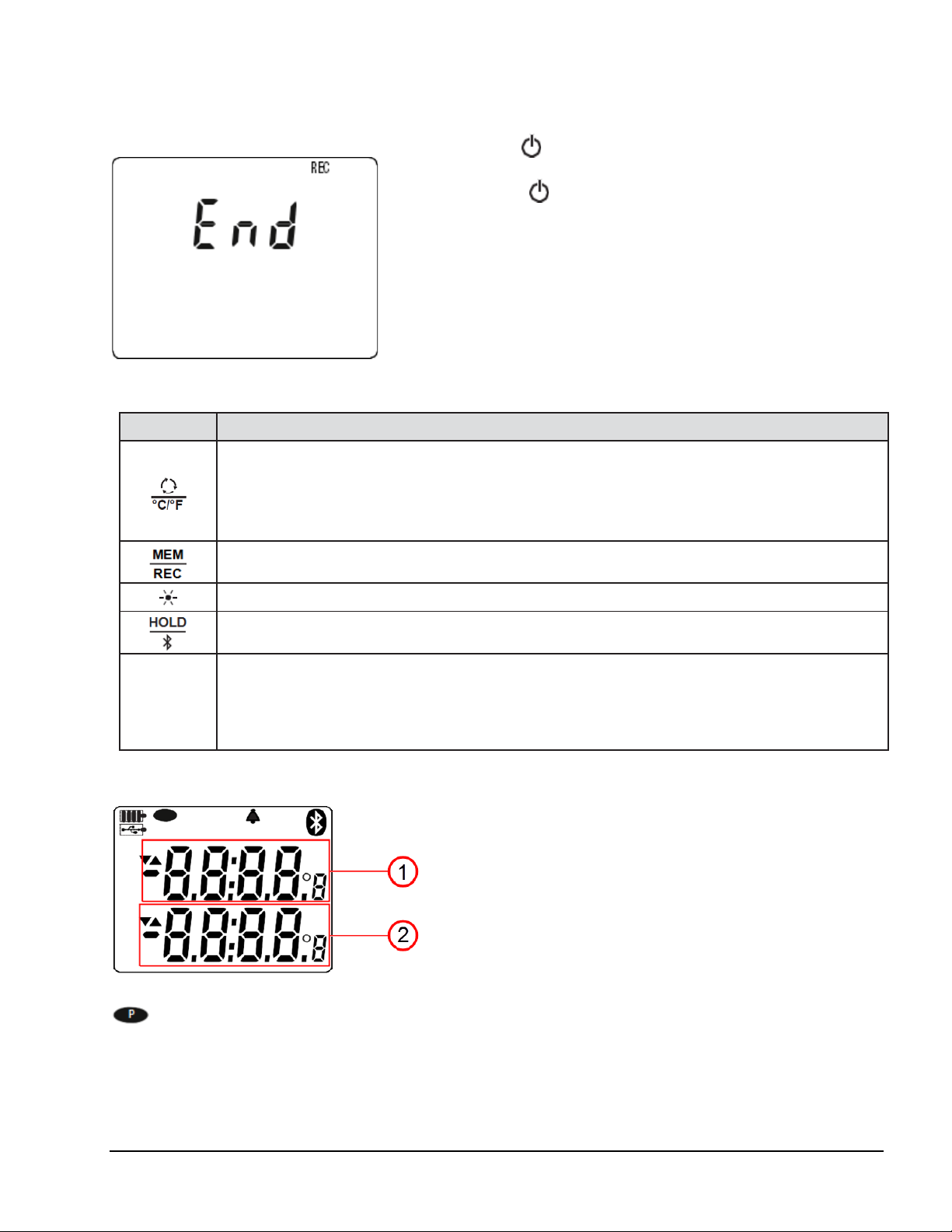
ON: Press the button for >2 seconds.
OFF: Press the button for >2 seconds when the instrument is
ON. Note that you cannot turn OFF the instrument when it is i
H
f the screen to the left appears during start-up, a recording session
I
was still in progress the last time the instrument was turned OFF. This
screen indicates the instrument is saving the recorded data.
D
o not turn OFF the instrument while this screen is displayed;
otherwise the recorded data will be lost.
1.5. Function Buttons
Button Function
Secondary (top) display: Relative humidity (RH). Main (bottom) display: Temperature (T)
Secondary display: Dew point (Dp). Main display: Relative humidity
Secondary display: Dew point. Main display: Temperature
Long press (>2 seconds) toggles between °C and °F.
n
OLD or in recording mode.
Second press displays the maximum value measured in MAX MIN mode.
MAX
MIN
Third press displays the minimum value.
Fourth press returns to current values.
Long press exits MAX MIN mode.
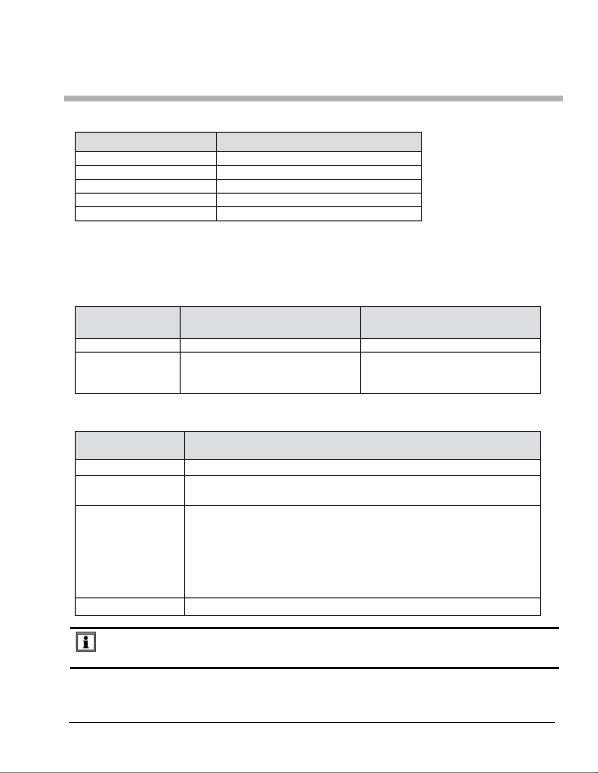
1.6. Display
1. MAP function counter
2.Main display
ndicates the measurement is outside the instrument limits (positive or negative).
OL i
indicates Auto OFF is disabled. This occurs when the instrument is:
Recording, in MAX MIN mode, in MAP mode, or in HOLD mode
Connected via the USB cable to an external power supply or an active USB port on a computer
Communicating via Bluetooth.
Set to Auto OFF disabled (see §2.4).Set to Auto OFF disabled (see §2.4).
8 Thermo-Hygrometer Data Logger Model 1246
Page 9

2. SETUP
Before using your instrument, you must set its date and time. If you plan to use alarms, you must define the
alarm threshold(s). Date/time and alarm settings must be configured through DataView. Other basic setup tasks
include selecting:
Bluetooth enabled (can be done on the instrument or via DataView)
°F or °C for measurement units (can be done on the instrument or via DataView)
Auto OFF interval (requires DataView)
2.1. DataView® Installation
1. Insert the USB drive that comes with the instrument into a USB port on your computer.
2. If Autorun is enabled, an AutoPlay window appears on your screen. Click “Open folder to view files” t
splay the DataView folder. If Autorun is not enabled or allowed, use Windows Explorer to locate and
di
open the USB drive labeled “DataView.”
3. When the DataView folder is open, find the file Setup.exe and double-click it.
4. The Setup screen appears. This enables you to select the language version of DataView to install.
You can also select additional install options (each option is explained in the Description field). Mak
your selections and click Install.
5. The InstallShield Wizard screen appears. This program leads you through the DataView install process.
As you complete these screens, be sure to check Data Loggers when prompted to select features t
stall.
in
6. When the InstallShield Wizard finishes installing DataView, the Setup screen appears. Click Exit t
lose. The DataView folder appears on your computer desktop.
c
o
e
o
o
2.2. Connecting the Instrument to a Computer
You can connect the instrument to a computer either through USB cable (provided with the instrument) or
Bluetooth
USB:
Bluetooth:
Connecting the instrument via Bluetooth requires a Bluegiga BLED112 Smart Dongle (sold separately) installed
in your computer. When the dongle is installed, do the following:
After the USB cable is connected or Bluetooth is activated, proceed as follows:
®
. The first two steps of the connection procedure depend on the connection type:
1. Connect the instrument to an available USB port using the supplied cable.
2. Turn ON the instrument. If this is the first time this instrument has been connected to this computer,
the drivers will be installed. Wait for driver installation to finish before proceeding with step 3 below.
1. Turn ON the instrument by pressing the button.
2. Activate Bluetooth on the instrument by pressing th
LCD.
3. Open the DataView folder on your desktop. This displays a list of icons for the Control Panel(s) install
with DataVie w.
4. Open the DataView Data Logger Control Panel by clicking the icon.
5. In the menu bar at the top of the screen, select Help. In the drop-down menu that appears, click t
ion Help Topics. This opens the Data Logger Control Panel Help system .
opt
6. Use the Contents window in the Help system to locate and open the topic "Connecting to a
nstrument." This provides instructions explaining how to connect your instrument to the computer.
I
7. When the instrument is connected, its name appears in the Data Logger Network folder in the left si
the Control Panel. A green check mark appears next to the name indicating it is currently connected.
of
e but
ton until the symbol appears in the
he
n
ed
de
Thermo-Hygrometer Data Logger Model 1246 9
Page 10

2.3. Instrument Date/Time
1. Select the instrument in the Data Logger Network.
2. In the menu bar, select Instrument. In the drop-down menu that appears, click Set Clock.
3. The Date/Time dialog box appears. Complete the fields in this dialog box. If you need assistance, press
F1.
4. When you are finished setting the date and time, click OK to save your changes to the instrument.
2.4. Auto OFF
By default, the instrument automatically turns OFF after 3 minutes of inactivity. You can use the Data Logger
Control Panel to change the Auto OFF interval, or disable this feature, as instructed by the Help that comes with
the software.
hen Auto OFF is disabled, the symbol appears in the instrument LCD screen.
W
2.5. Temperature Units
The button on the instrument front panel allows you to toggle between °C and °F as the temperature
measurement unit. You can also set this through the Data Logger Control Panel.
2.6. Alarms
You can program alarm thresholds on each of the measurement channels using the DataView Data Logger
Control Panel. For information about using alarms see §3.3.
10 Thermo-Hygrometer Data Logger Model 1246
Page 11

3. STANDALONE OPERATION
The instrument can operate in two modes:
Stand-alone mode, described in this section
Remote mode, in which the instrument is controlled by a computer running DataView (see §4)
3.1. Making Measurements
1. Remove the cap protecting the sensor.
2. If the instrument is OFF, press and hold down the button until it
turns ON. The instr ument displays the time, then the relative humidity
(top) and temperature (bottom) measurements. (The time is set vi
D
ataView; see §2.3.)
a
3. Press the button to change the displayed measurements. T
f
irst press displays dew point (top) and relative humidity (bottom). A
second press shows dew point and temperature. A third press
restores the original measurements.
4. To change temperature units, press and hold down until the
desired unit (°C or °F) is displayed.
Note that the last measurement display selected is saved when the instrument is turned OFF.
Relative humidity (RH) is the ratio of the quantity of water vapor contained in a volume of air to the
maximum quantity this same volume of air can contain at the current temperature.
Dew point is the lowest temperature to which a mass of air can be subjected, at constant pressure and
absolute humidity,
Keep the sensor away from your mouth to avoid affecting the humidity measurement.
Wait for the display to stabilize before reading the measurement.
3.1.1. HOLD Function
Pressing the button freezes the display. A second press unfreezes it.
3
.1.2. MAX MIN Function
You can monitor the maximum and minimum measurements by pressing the button. This displays the
words MIN MAX at the top of the display (see the following illustration). In this mode, pressing once
displays the maximum value measured during the current session. A second press displays the minimum. A
third press restores the normal display. Subsequent presses of repeat this cycle.
without liquid water forming by saturation.
he
T
o exit MAX MIN mode, long-press .
Thermo-Hygrometer Data Logger Model 1246 11
Page 12

3.2. Recording Measurements
You can start and stop a recording session on the instrument. Recorded data is stored in the instrument’s
memory, and can be downloaded and viewed on a computer running the DataView Data Logger Control Panel.
ou can record data by pressing the button:
Y
A short press (MEM) records the current measurement(s) and date.
A long press (REC) starts the recording session. While the recording is in progress, the symbol REC
appears at the top of the display. A second long press of stops the recording session. Note that
while the instrument is recording, a short press of has no effect.
chedule recording sessions, and download and view recorded data, see the DataView Data Logger
To s
Control Panel Help.
3.3. Alarms
You can program alarm thresholds via the DataView Data Logger Control Panel. In standalone mode, if an
alarm threshold is programmed, the symbol is displayed. When a threshold is crossed, the symbol blinks,
and one of the following blinking symbols appears to the right of the measurement:
indicates measurement is above the high threshold.
indicates measurement is below the low threshold.
indicates the measurement is between the two thresholds.
3.4. Errors
The instrument detects errors and displays them in the form Er.XX:
Er.01
Er.02
Er.03
Er.10
Er.11
Er.12
Er.13
Hardware malfunction detected. The instrument must be sent in for repair.
Internal memory error. Connect the instrument to a computer via the USB cable and format its memory
using Windows.
Hardware malfunction detected. The instrument must be sent in for repair.
The instrument has not been correctly adjusted. The instrument must be sent to customer service.
The firmware is incompatible with the instrument. Install the correct firmware (see §6.3).
The firmware version is incompatible with the instrument. Reload the previous firmware version.
Recording scheduling error. Ensure that the instrument’s time and the time of the DataView Data
Logger Control Panel are the same (see §2.3).
12 Thermo-Hygrometer Data Logger Model 1246
Page 13

4. DATAVIEW
As explained in §2, DataView® is required to perform several basic setup tasks including connecting the
instrument to a computer, setting the time and date on the instrument, and changing the Auto OFF setting. In
addition, DataView allows you to:
Configure and schedule a recording session on the instrument.
Download recorded data from the instrument to the computer.
Generate reports from downloaded data.
View instrument measurements in real time on the computer.
F
or information about performing these tasks, consult the DataView Data Logger Control Panel Help.
Thermo-Hygrometer Data Logger Model 1246 13
Page 14
5. TECHNICAL CHARACTERISTICS
Temperature
73 ± 3.6°F (23 ± 2°C)
Relative humidity
45% to 75%
Supply voltage
3 to 4.5V
Electric field
< 1V/m
Magnetic field
< 40A/m
measurement range
Resolution
0.1°F
0.1°C
Specified
3 to 98% RH
5.1. Reference Conditions
Quantity of influence Reference values
The intrinsic uncertainty is the error specified for the reference conditions.
θ
= temperature
R = reading.
5.2. Electrical Specifications
5.2.1. Temperature Measu rem ent
Specified
Intrinsic uncertainty from 50 to 104°F: ± (0.9°F ± 1 pt)
outside this range: ± (0.032 x (T-25) ±
T = temperature in °C
5.2.2. Humidity Measurement
measurement range
Resolution 0.1 %HR
Intrinsic uncertainty from 10 to 90% RH: ± (2% RH ± 1 pt)
Hysteresis ± 1% RH
If the humidity sensor is exposed for an extended period to a relative humidity
below 10% RH or above 80% RH, subsequent measurements will be offset.
The longer the exposure, the larger the offset.
This offset can reach 3% RH if the sensor remains for 60 hours at 90% RH. The
offset
will disappear after 5 days at ambient temperature (68 to 86° [20 to 30°C]
and 40 to 60% RH).
14 to 140°F -10 to 60°C
1 pt)
outside of this range: ± (4% RH ± 1 pt)
from 10 to 40°C: ± (0.5°C ± 1 pt)
outside this range: ± (0.032 x (T-25) ±
1 pt)
Long-term drift <0.5% RH per year
14 Thermo-Hygrometer Data Logger Model 1246
A sensor exposed to a high temperature (for example in a car in direct sunlight) will also be exposed
to a very low relative humidity. In these cases, several days of recovery at ambient temperature will be
necessary.
Page 15

5.2.3. Dew Point Measurement
Specified
measurement range
Resolution
Display in °F: 0.1°F
Display in °C: 0.1°C
from 20 to 30%RH: ± 2.7°F
from 20 to 30%RH: ± 1.5°C
14 to 140°F -10 to 60°C
Intrinsic uncertainty
5.
2.4. Psychometric Diagram
>30%RH: ± 1.8°F
>30%RH: ± 1°C
Air consists of dry atmospheric gasses (nitrogen, oxygen, etc.) and water vapor. The maximum amount of water
vapor a volume of air can hold depends on its temperature. Beyond this maximum, any additional water vapor
immediately condenses into liquid water droplets, creating fog, dew, and other forms of condensate. This
phenomenon is known as saturation, and the temperature at which it occurs is called the dew point. The amount
of water vapor in the air is called humidity. This is typically expressed two ways:
Absolute humidity (measured in units such as grams of water per kilograms of air) is the amount of
water vapor in the air. This is independent o f temperature.
Relative humidity (measured as a percentage) is the ratio of absolute humidity to the maximum amount
of water vapor a volume of air can hold at its dew point.
A psychometric chart known as a Mollier diagram (see below) displays absolute humidity versus temperature
for different values of relative humidity. This chart is useful for determining the absolute humidity and dew point
for air at a given relative humidity and temperature.
A
bsolute humidity (g of water/kg of dry air)
For example, in the preceding chart, the blue lines indicate that for air 21°C (70°F) and 60% RH, the absolute
humidity is 9.3g/kg and the dew point is 12.8°C (55°F).
Thermo-Hygrometer Data Logger Model 1246 15
\
Temperature (°C)
Page 16

5.2.5. Influence of Temperature o n th e Relative Humidity Measurement
Relative humidity (%)
Temperature (°C)
The relative humidity is highly dependent on the temperature. To calibrate the instrument, the two sensors (the
reference sensor and the sensor of the instrument) must indicate the same temperatur e. At each measurement,
you must note both values: the temperature and the relative humidity. They are inseparable.
5.2.6. Response Time
Typical response time with an air speed of (6.6M/S (2m/s):
Temperature: τ(66%) = 30s and τ(90%) = 90s.
Relative humidity: τ(66%) = 60s and τ(90%) = 150s.
66%): Response time to 66%
τ(
τ(90%): Response time to 90%
5.3. Memory
The instrument has 8MB of flash memory, sufficient to record and store a million measurements. Each record
contains the measurement value, date and time, and unit of measure.
5.4. USB
Protocol: USB Mass Storage
Maximum transmission speed: 12 Mbit/s Type B micro-USB connector
16 Thermo-Hygrometer Data Logger Model 1246
Page 17

5.5. Bluetooth
Bluetooth 4.0 BLE
Range 32’ (10m) typical and up to 100’ (30m) in line of sight.
Output power: +0 to -23dBm
Nominal sensitivity: -93dBm
Maximum transfer rate: 10 kbits/s
Average consumption: 3.3µA at 3.3V
5.6. Power Supply
The instrument is powered by three 1.5V LR6 or AA alkaline batteries. You can replace the batteries with
rechargeable NiMH batteries of the same size. However, even when the rechargeable batteries are fully
charged, they will not reach the voltage of the alkaline batteries, and the Battery indicator will appear as or
.
oltage for correct operation is 3 to 4.5V for alkaline batteries and 3.6V for rechargeable batteries. Below 3V,
V
the instrument stops taking measurements and displays the message BAt.
B
attery life (with Bluetooth deac ti vat ed) is :
standby mode: 500 hours
recording mode: 3 years at rate of one measurement every 15 minutes
T
he instrument can also be powered via a USB-micro cable, connected to either a computer or wall outlet
adapter.
5.7. Environmental Conditions
For use indoors and outdoors.
Operating range: +14 to +140°F (-10 to 60°C) and 10 to 90%RH without condensation
Storage range: -4 to +158°F (-20 to +70°C) and 10 to 95%RH without condensation, without batteries
Altitude: <6562’ (2000m), and 32,808’ (10,000m) in storage
Pollution degree: 2
5.8. Mechanical Specif icat io ns
Dimensions (L x W x H): 7.36 x 2.83 x 1.26” (187 x 72 x 32mm)
Mass: approximately 9.17oz (260g)
Inrush protection: IP 54, with the USB connector closed and protective cap in place, per IEC 60 529
Drop impact test: 3.2’ (1m) per IEC 61010-1
5.9. Compliance with Internati onal Standards
The instrument is compliant with standard IEC 61010-1.
5.10. Electromagnetic Compatibility (CEM)
The instrument is compliant with standard IEC 61326-1.
Thermo-Hygrometer Data Logger Model 1246 17
Page 18

6. MAINTENANCE
Except for batteries, the instrument contains no parts that can be replaced by personnel who
have not been specially trained and accredited. Any unauthorized repair or replacement of a part
by an “equivalent” may significantly impair safety.
6.1. Cleaning
1. Turn the instrument OFF.
2. Clean instrument with a soft cloth, dampened with soapy water.
3. Rinse with a damp cloth and dry rapidly with a dry cloth or forced air. Do not use alcohol, solvents, or
hydrocarbons.
6.2. Battery Replacement
The symbol indicates the remaining battery life. When the symbol is empty, all of the batteries must be
replaced. To do this, turn the instrument OFF and refer to §1.4 for the replacement procedure.
Spent batteries must not be treated as ordinary household waste. Take them to an appropriate recycling
facility.
6.3. Firmware Update
AEMC may periodically update the instrument’s firmware. Updates are available for free download. To check for
updates:
1. C
onnect the instrument to the Data Logger Control Panel.
2. Click Help.
3. Click Update. If the instrument is running the latest firmware, a message appears informing you of this.
If an update is available, the AEMC Download page automatically opens. Follow the instructions list
on this page to download the update.
After firmware updates, it may be necessary to reconfigure the instrument (see §2).
ed
18 Thermo-Hygrometer Data Logger Model 1246
Page 19

REPAIR AND CALIBRATION
To ensure that your instrument meets factory specifications, we recommend that it be scheduled to be sent
back to our factory Service Center at one-year intervals for recalibration, or as required by other standards or
internal procedures.
or instrument repair and calibration:
F
You must contact our Service Center for a Customer Service Authorization Number (CSA#). This will ensure
that when your instrument arrives, it will be tracked and processed promptly. Please write the CSA# on the
outside of the shipping container. If the instrument is returned for calibration, we need to know if you want a
standard calibration or a calibration traceable to N.I.S.T. (includes calibration certificate plus recorded
calibration data).
For North / Central / South America, Australia and New Zealand:
®
Ship To: Chauvin Arnoux
15 Faraday Drive • Dover, NH 03820 USA
Phone: (800) 945-2362 (Ext. 360)
Fax: (603) 742-2346 • (603) 749-6309
E-mail: repair@aemc.com
(Or contact your authorized distributor.)
, Inc. d.b.a. AEMC® Instruments
(603) 749-6434 (Ext. 360)
Costs for repair, standard calibration, and calibration traceable to N.I.S.T. are available.
NOTE: You must obtain a CSA# before returning any instrument.
TECHNICAL AND SALES ASSISTANCE
If you are experiencing any technical problems, or require any assistance with the proper operation or
application of your instrument, please call, fax, or e-mail our technical support team:
®
Contact: Chauvi n Arnoux
Phone: (800) 945-2362 (Ext. 351) • (603) 749-6434 (Ext. 351)
Fax: (603) 742-2346
E-mail: techsupport@aemc.com
, Inc. d.b.a. AEMC® Instruments
Thermo-Hygrometer Data Logger Model 1246 19
Page 20

LIMITED WARRANTY
Your AEMC instrument is warranted to the owner for a period of two years from the date of original purchase
against defects in manufacture. This limited warranty is given by AEMC
whom it was purchased. This warranty is void if the unit has been tam pered with, abused, or if the defect is
related to service not performed by AEMC
®
Instruments.
®
Instruments, not by the distributor from
Full warranty coverage and product registration is available on our website at:
www.aemc.com/warranty.html.
Please print the online Warranty Coverage Information for your records.
What AEMC
If a malfunction occurs within the warranty period, you may return the instrument to us for repair, provided we
have your warranty registration information on file or a proof of purchase. AEMC
®
Instruments will do:
®
Instruments will, at its option,
repair or replace the faulty material.
Warranty Repairs
What you must do to return an Instrument for Warranty Repair:
First, request a Customer Service Authorization Number (CSA#) by phone or by fax from our Service
Department (see address below), then return the instrument along with the signed CSA Form. Please write the
CSA# on the outside of the shipping container. Return the instrument, postage or shipment pre-paid to:
®
Ship To: Chauvin Arnoux
, Inc. d.b.a. AEMC® Instruments
15 Faraday Drive • Dover, NH 03820 USA
Phone: (800) 945-2362 (Ext. 360)
(603) 749-6434 (Ext. 360)
Fax: (603) 742-2346 • (603) 749-6309
E-mail: repair@aemc.com
Caution: To protect yourself against in-transit loss, we recommend you insure your returned material.
NOTE: You must obtain a CSA# before returning any instrument.
20 Thermo-Hygrometer Data Logger Model 1246
Page 21

NOTES:
Thermo-Hygrometer Data Logger Model 1246 21
Page 22

NOTES:
22 Thermo-Hygrometer Data Logger Model 1246
Page 23

NOTES:
Thermo-Hygrometer Data Logger Model 1246 23
Page 24

01/18
99-MAN 100451 v1
Chauvin Arnoux®, Inc. d.b.a. AEMC® Instruments
15 Faraday Drive • Dover, NH 03820 USA • Phone: (603) 749-6434 • Fax: (603) 742-2346
www.aemc.com
 Loading...